EP0242975A2 - Wrapping machine - Google Patents
Wrapping machine Download PDFInfo
- Publication number
- EP0242975A2 EP0242975A2 EP87302247A EP87302247A EP0242975A2 EP 0242975 A2 EP0242975 A2 EP 0242975A2 EP 87302247 A EP87302247 A EP 87302247A EP 87302247 A EP87302247 A EP 87302247A EP 0242975 A2 EP0242975 A2 EP 0242975A2
- Authority
- EP
- European Patent Office
- Prior art keywords
- length
- bale
- wrapping machine
- roll
- machine according
- Prior art date
- Legal status (The legal status is an assumption and is not a legal conclusion. Google has not performed a legal analysis and makes no representation as to the accuracy of the status listed.)
- Withdrawn
Links
Images

Classifications
-
- A—HUMAN NECESSITIES
- A01—AGRICULTURE; FORESTRY; ANIMAL HUSBANDRY; HUNTING; TRAPPING; FISHING
- A01F—PROCESSING OF HARVESTED PRODUCE; HAY OR STRAW PRESSES; DEVICES FOR STORING AGRICULTURAL OR HORTICULTURAL PRODUCE
- A01F15/00—Baling presses for straw, hay or the like
- A01F15/07—Rotobalers, i.e. machines for forming cylindrical bales by winding and pressing
- A01F15/071—Wrapping devices
-
- B—PERFORMING OPERATIONS; TRANSPORTING
- B65—CONVEYING; PACKING; STORING; HANDLING THIN OR FILAMENTARY MATERIAL
- B65B—MACHINES, APPARATUS OR DEVICES FOR, OR METHODS OF, PACKAGING ARTICLES OR MATERIALS; UNPACKING
- B65B11/00—Wrapping, e.g. partially or wholly enclosing, articles or quantities of material, in strips, sheets or blanks, of flexible material
- B65B11/04—Wrapping, e.g. partially or wholly enclosing, articles or quantities of material, in strips, sheets or blanks, of flexible material the articles being rotated
- B65B11/045—Wrapping, e.g. partially or wholly enclosing, articles or quantities of material, in strips, sheets or blanks, of flexible material the articles being rotated by rotating platforms supporting the articles
-
- A—HUMAN NECESSITIES
- A01—AGRICULTURE; FORESTRY; ANIMAL HUSBANDRY; HUNTING; TRAPPING; FISHING
- A01F—PROCESSING OF HARVESTED PRODUCE; HAY OR STRAW PRESSES; DEVICES FOR STORING AGRICULTURAL OR HORTICULTURAL PRODUCE
- A01F15/00—Baling presses for straw, hay or the like
- A01F15/07—Rotobalers, i.e. machines for forming cylindrical bales by winding and pressing
- A01F15/071—Wrapping devices
- A01F2015/0725—Film dispensers for film rollers in a satellite type wrapper, e.g. holding and tensioning means for the film roller
-
- A—HUMAN NECESSITIES
- A01—AGRICULTURE; FORESTRY; ANIMAL HUSBANDRY; HUNTING; TRAPPING; FISHING
- A01F—PROCESSING OF HARVESTED PRODUCE; HAY OR STRAW PRESSES; DEVICES FOR STORING AGRICULTURAL OR HORTICULTURAL PRODUCE
- A01F15/00—Baling presses for straw, hay or the like
- A01F15/07—Rotobalers, i.e. machines for forming cylindrical bales by winding and pressing
- A01F15/071—Wrapping devices
- A01F2015/0755—Configuration of support surfaces which can move in order to rotate a bale around at least one axis while wrapping
Definitions
- This invention relates to wrapping machines and in particular to wrapping machines for wrapping bales, for example, bales of crop materials such as grass for silage.
- a wrapping machine for bales comprises a turntable rotatable about an upright axis, a pair of rollers rotatable about parallel, generally horizontal axes, and dispensing means for dispensing a length of stretchable plastics for wrapping the bales, the bales being locatable for support and rotation on the rollers during dispensing of the plastics length so that the bales rotate about said horizontal and upright axes, the dispensing means including a support for the length of plastics and means for tensioning the length as it is dispensed, the tensioning means including an adjustment device whereby the tension is adjustable.
- the tensioning means is hydraulically-operated and provides hydraulically a resistance to the release of a length of plastics from a roll.
- the unwinding of the roll drives a hydraulic pump and an adjustable hydraulic valve controls the fluid flow from the pump to control the resistance to release of the length and thereby tension the plastics length as it is wound round the bale.
- rollers of the pair are set at different levels the rollers being rotatable in the same direction as one another, and the roller towards which the bale is tending to roll being set at a higher level than the other roller to thereby inhibit any tendency for the bale to roll off the rollers during operation.
- a bale wrapping machine includes a frame 10 which, as shown in Fig. 3, is arranged to be supported on the ground but it may instead be mounted on a trailer or like mobile unit.
- the frame 10 is of generally rectangular structure having ground engaging legs 11 and it also supports stretch film dispensing means 12 on an upright support arm 13.
- An hydraulically-operated motor 14 is carried towards the centre of the frame 10 and is fixed thereto.
- the motor 14 is powered by a source of pressurised fluid, typically the hydraulic supply of a tractor or an independent power pack (not shown).
- the motor 14 has an output shaft 15 which drives a turntable 17, rotatably carried on the frame 10, about the axis of the shaft 15 which extends generally vertically.
- the shaft 15 also carries a chain sprocket 18 around which a chain 19 passes from sprocket 18 to drive a sprocket 20.
- the sprocket 20 in turn drives a bevel gearbox 21 from which an output shaft 22 drives a further, double sprocket 24.
- a chain 25 passes around each of the sprockets 24 to drive a roller sprocket 26, one mounted on the end of a roller 27 and a roller 28.
- the rollers 27, 28 are supported on the turntable 17 for rotation about parallel axes in the same direction as one another, as indicated by arrows A.
- the rollers 27, 28 are each mounted in bearings 29 at opposite ends, the bearings being fixed to turntable frame members 30.
- one of the rollers 27 is set at a higher level than the other roller 28 by providing brackets 31 between the frame members 30 and the roller 27 to raise the roller 27 relative to the associated frame member 30.
- a suitable difference in level is of the order of 5 cms.
- the rollers 27, 28 are conveniently of a form having a generally cylindrical outer surface with a plurality of dimples distributed over the surface.
- the speed of rotation of the turntable 17 is matched to the speed of rotation of the rollers 27, 28 so that the bale (not shown) is wrapped and sealed adequately during continuous rotation of the bale about the vertical and horizontal axes.
- Bale wrapping material in the form of a length of stretchable plastics film of the appropriate width is dispensed from a roll of such film (not shown) which is mounted on the dispensing means 12.
- the roll which has a hollow centre is fitted rotatably on a support 43 which has its axis extending vertically.
- a roller 32 having a raised spiral 33 about its periphery is mounted on a spindle 34 in bearings 35 carried on support brackets and the spindle 34 drives a hydraulic pump 37 when the roller 32 rotates.
- the output from the pump 37 passes to an adjustable hydraulic valve 38 and from thence is delivered through hose 39 to a reservoir in the support 13.
- a further hose 39A feeds fluid to the pump 37 from the reservoir.
- the film After passing from the roll the film is guided towards the roller 32 by guide rollers 42 which are mounted to be freely rotatable about their axes.
- Operation of the wrapping machine is achieved by locating a bale to be wrapped on the rollers 27 and 28 and locating a roll of the film on the support 43.
- the end of the length of film is drawn out from the film roll and is tied to the bale either to baler twine around the bale or to baler netting around the bale.
- the tension in the film is checked usually by the operator checking the width of the film passing from the bale to the roll.
- the bale is rotated about the vertical and horizontal axes by operation of the motor 14. During the rotation the film is overlapped on itself on the bale by about 50% and the rotation continues until the bale is completely envelopped in material whereupon the film length is severed adjacent the dispensing means 12 and is secured to the wrapped bale.
- the desired tension in the length of film will be affected by ambient temperatures, the nature of the film used and other factors. If the film is not correctly tensioned a loose or overtight wrapping will be formed with loss of sealing of the material in the bale.
- the adjustable tensioning arrangement enables different conditions to be provided for in a quick and simple manner.
- two such turntables may be provided side by side so that as a bale is wrapped on one turntable a bale can be loaded and unloaded from the other turntable.
- one film dispenser can be used for both turntables.
Abstract
A wrapping machine for bales of crop wraps stretchable film around the bales to seal the bales from atmosphere.
The machine includes a turntable 17 rotatable about a vertical axis, and on the turntable are a pair of rollers 27, 28 rotatable about horizontal axes.
Film dispensing means 12 is located adjacent the turntable to dispense film for wrapping the bales during their rotation about the vertical and horizontal axes.
Film is dispensed at a controlled tension which can be adjusted by a hydraulic pump 37 driven through movement of the film, fluid from the pump passing through an adjustable valve 38.
Description
- This invention relates to wrapping machines and in particular to wrapping machines for wrapping bales, for example, bales of crop materials such as grass for silage.
- It has been proposed, as for example in British patent application No. 2159489, to wrap large round bales in a length of stretchable film by means of driven rollers supporting the bale about a generally horizontal axis, the rollers being mounted for rotation about a vertical axis.
- It is an object of the invention to provide an improved wrapping machine.
- According to the invention a wrapping machine for bales comprises a turntable rotatable about an upright axis, a pair of rollers rotatable about parallel, generally horizontal axes, and dispensing means for dispensing a length of stretchable plastics for wrapping the bales, the bales being locatable for support and rotation on the rollers during dispensing of the plastics length so that the bales rotate about said horizontal and upright axes, the dispensing means including a support for the length of plastics and means for tensioning the length as it is dispensed, the tensioning means including an adjustment device whereby the tension is adjustable.
- Preferably the tensioning means is hydraulically-operated and provides hydraulically a resistance to the release of a length of plastics from a roll. In one arrangement the unwinding of the roll drives a hydraulic pump and an adjustable hydraulic valve controls the fluid flow from the pump to control the resistance to release of the length and thereby tension the plastics length as it is wound round the bale.
- According to a further feature of the invention the rollers of the pair are set at different levels the rollers being rotatable in the same direction as one another, and the roller towards which the bale is tending to roll being set at a higher level than the other roller to thereby inhibit any tendency for the bale to roll off the rollers during operation.
- Further features of the invention will appear from the following description of an embodiment of the invention given by way of example only and with reference to the drawings, in which:-
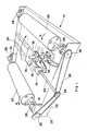
- Fig. 1 is a perspective view of a turntable and drive for a bale wrapping machine,
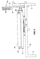
- Fig. 2 is a perspective view of a dispenser for plastics film for the wrapping machine, and
- Fig. 3 is a side elevation of the bale wrapping machine.
- Referring to the drawings a bale wrapping machine includes a
frame 10 which, as shown in Fig. 3, is arranged to be supported on the ground but it may instead be mounted on a trailer or like mobile unit. Theframe 10 is of generally rectangular structure having groundengaging legs 11 and it also supports stretch film dispensing means 12 on anupright support arm 13. - An hydraulically-operated
motor 14 is carried towards the centre of theframe 10 and is fixed thereto. Themotor 14 is powered by a source of pressurised fluid, typically the hydraulic supply of a tractor or an independent power pack (not shown). - The
motor 14 has anoutput shaft 15 which drives aturntable 17, rotatably carried on theframe 10, about the axis of theshaft 15 which extends generally vertically. Theshaft 15 also carries achain sprocket 18 around which achain 19 passes fromsprocket 18 to drive asprocket 20. - The
sprocket 20 in turn drives abevel gearbox 21 from which anoutput shaft 22 drives a further, double sprocket 24. Achain 25 passes around each of thesprockets 24 to drive aroller sprocket 26, one mounted on the end of aroller 27 and aroller 28. - The
rollers turntable 17 for rotation about parallel axes in the same direction as one another, as indicated by arrows A. Therollers bearings 29 at opposite ends, the bearings being fixed toturntable frame members 30. However one of therollers 27 is set at a higher level than theother roller 28 by providingbrackets 31 between theframe members 30 and theroller 27 to raise theroller 27 relative to the associatedframe member 30. A suitable difference in level is of the order of 5 cms. Therollers - The speed of rotation of the
turntable 17 is matched to the speed of rotation of therollers - Bale wrapping material in the form of a length of stretchable plastics film of the appropriate width is dispensed from a roll of such film (not shown) which is mounted on the dispensing means 12. The roll which has a hollow centre is fitted rotatably on a
support 43 which has its axis extending vertically. Aroller 32 having a raisedspiral 33 about its periphery is mounted on aspindle 34 inbearings 35 carried on support brackets and thespindle 34 drives ahydraulic pump 37 when theroller 32 rotates. The output from thepump 37 passes to an adjustablehydraulic valve 38 and from thence is delivered throughhose 39 to a reservoir in thesupport 13. A further hose 39A feeds fluid to thepump 37 from the reservoir. - Film passing from the roll on the
support 43 around theroller 32 rotates theroller 32 and thespindle 34 as the film is unwound and thepump 37 provides a resistance to rotation, the amount of resistance depending on the setting of thevalve 38 and this resistance being adjustable by avalve adjustment member 40. - After passing from the roll the film is guided towards the
roller 32 byguide rollers 42 which are mounted to be freely rotatable about their axes. - Operation of the wrapping machine is achieved by locating a bale to be wrapped on the
rollers support 43. The end of the length of film is drawn out from the film roll and is tied to the bale either to baler twine around the bale or to baler netting around the bale. The tension in the film is checked usually by the operator checking the width of the film passing from the bale to the roll. The bale is rotated about the vertical and horizontal axes by operation of themotor 14. During the rotation the film is overlapped on itself on the bale by about 50% and the rotation continues until the bale is completely envelopped in material whereupon the film length is severed adjacent the dispensing means 12 and is secured to the wrapped bale. - The desired tension in the length of film will be affected by ambient temperatures, the nature of the film used and other factors. If the film is not correctly tensioned a loose or overtight wrapping will be formed with loss of sealing of the material in the bale. The adjustable tensioning arrangement enables different conditions to be provided for in a quick and simple manner.
- Instead of the machine having a single turntable two such turntables may be provided side by side so that as a bale is wrapped on one turntable a bale can be loaded and unloaded from the other turntable. In this case one film dispenser can be used for both turntables.
Claims (7)
1. A wrapping machine for bales which comprises a turntable 17 rotatable about an upright axis, a pair of rollers 27, 28 mounted on the turntable and rotatable about parallel, generally horizontal axes, and dispensing means 12 for dispensing a length of stretchable plastics for wrapping the bales, a bale being locatable for support and rotation on the rollers during dispensing of the plastics length so that the bale rotates about said horizontal and upright axes, the dispensing means including a support 43 for the length of plastics, and means 37, 38 for tensioning the length as it is dispensed, characterised in that the tensioning means includes an adjustment device 38 whereby the tension in the length is adjustable.
2. A wrapping machine according to claim 1 characterised in that the tensioning means 37, 38 is hydraulically operated and provides hydraulically a resistance to the feed of the plastics length from a roll thereof carried on the support 43.
3. A wrapping machine according to claim 2 characterised in that the tensioning means includes a hydraulic pump 37 driven by passage of the length from the roll to the bale and an adjustable hydraulic valve 38 controls the fluid flow from the pump.
4. A wrapping machine according to claim 3 characterised in that the pump 37 is coupled to a roller 32 around which the length passes in extending between the roll and the bale and unwinding of the length from the roll causes the roller to rotate and drive the pump 37.
5. A wrapping machine according to claim 2, 3, or 4 characterised in that the fluid from the tensioning means 37, 38 passes through a closed circuit 13, 39, 39A including a fluid reservoir 13.
6. A wrapping machine according to any one of the preceding claims characterised in that one of the bale supporting rollers 27 is set at a higher level than the other supporting roller 28 of the pair, the higher roller being that towards which the bale is tending to roll during a wrapping operation.
7. A wrapping machine according to any one of the preceding claims characterised by two side by side turntables 17, each for supporting a bale to be wrapped, and a common dispensing means 12 for the turntables.
Applications Claiming Priority (4)
| Application Number | Priority Date | Filing Date | Title |
|---|---|---|---|
| GB868607144A GB8607144D0 (en) | 1986-03-22 | 1986-03-22 | Ideal cover wrapping machine |
| GB8607144 | 1986-03-22 | ||
| GB8628270A GB2188024B (en) | 1986-03-22 | 1986-11-26 | Wrapping machine |
| GB8628270 | 1986-11-26 |
Publications (2)
| Publication Number | Publication Date |
|---|---|
| EP0242975A2 true EP0242975A2 (en) | 1987-10-28 |
| EP0242975A3 EP0242975A3 (en) | 1988-03-09 |
Family
ID=26290524
Family Applications (1)
| Application Number | Title | Priority Date | Filing Date |
|---|---|---|---|
| EP87302247A Withdrawn EP0242975A3 (en) | 1986-03-22 | 1987-03-17 | Wrapping machine |
Country Status (1)
| Country | Link |
|---|---|
| EP (1) | EP0242975A3 (en) |
Cited By (7)
| Publication number | Priority date | Publication date | Assignee | Title |
|---|---|---|---|---|
| WO1994020367A1 (en) * | 1993-03-12 | 1994-09-15 | Kenneth Stephen Eddin Orpen | Hydraulic bale wrapper |
| WO1997000202A1 (en) * | 1995-06-16 | 1997-01-03 | Kenneth Stephen Eddin Orpen | Improved wrapping methods and apparatus |
| ES2101662A1 (en) * | 1996-10-07 | 1997-07-01 | Zubeldia Angel Maria Lacunza | Machine for wrapping circular bales of fodder |
| WO1998026648A1 (en) | 1996-12-18 | 1998-06-25 | Kenneth Stephen Eddin Orpen | Wrapping apparatus |
| KR100582102B1 (en) | 2005-03-02 | 2006-05-22 | 대한민국(관리부서:농촌진흥청) | Round bale wrapper |
| EP2156728A3 (en) * | 2008-08-21 | 2012-11-07 | Kuhn-Geldrop B.V. | Bale wrapper apparatus |
| EP3440924A1 (en) * | 2017-08-11 | 2019-02-13 | Vermeer Manufacturing Company | Hydraulic brake for bale wrap material |
Citations (5)
| Publication number | Priority date | Publication date | Assignee | Title |
|---|---|---|---|---|
| US1398875A (en) * | 1920-02-20 | 1921-11-29 | Michael D Maloney | Mechanical brake |
| US4079565A (en) * | 1974-03-25 | 1978-03-21 | Lantech Inc. | Stretch-wrapped package, process and apparatus |
| GB1546523A (en) * | 1977-10-07 | 1979-05-23 | Inpac Automation Ltd | Stretch wrapping apparatus |
| FR2552969A1 (en) * | 1983-10-07 | 1985-04-12 | Krone Bernhard Gmbh Maschf | DEVICE FOR ENVELOPING ROUND BALES IN AGRICULTURAL HARVEST BALL PRESSES |
| US4514955A (en) * | 1981-04-06 | 1985-05-07 | Lantech, Inc. | Feedback controlled stretch wrapping apparatus and process |
-
1987
- 1987-03-17 EP EP87302247A patent/EP0242975A3/en not_active Withdrawn
Patent Citations (5)
| Publication number | Priority date | Publication date | Assignee | Title |
|---|---|---|---|---|
| US1398875A (en) * | 1920-02-20 | 1921-11-29 | Michael D Maloney | Mechanical brake |
| US4079565A (en) * | 1974-03-25 | 1978-03-21 | Lantech Inc. | Stretch-wrapped package, process and apparatus |
| GB1546523A (en) * | 1977-10-07 | 1979-05-23 | Inpac Automation Ltd | Stretch wrapping apparatus |
| US4514955A (en) * | 1981-04-06 | 1985-05-07 | Lantech, Inc. | Feedback controlled stretch wrapping apparatus and process |
| FR2552969A1 (en) * | 1983-10-07 | 1985-04-12 | Krone Bernhard Gmbh Maschf | DEVICE FOR ENVELOPING ROUND BALES IN AGRICULTURAL HARVEST BALL PRESSES |
Cited By (14)
| Publication number | Priority date | Publication date | Assignee | Title |
|---|---|---|---|---|
| WO1994020367A1 (en) * | 1993-03-12 | 1994-09-15 | Kenneth Stephen Eddin Orpen | Hydraulic bale wrapper |
| US5816026A (en) * | 1993-03-12 | 1998-10-06 | Orpen; Kenneth Stephen Eddin | Hydraulic bale wrapper |
| US5979146A (en) * | 1995-06-16 | 1999-11-09 | Orpen; Kenneth Stephen Eddin | Wrapping methods and apparatus |
| WO1997000202A1 (en) * | 1995-06-16 | 1997-01-03 | Kenneth Stephen Eddin Orpen | Improved wrapping methods and apparatus |
| AU704734B2 (en) * | 1995-06-16 | 1999-04-29 | Kenneth Stephen Eddin Orpen | Improved wrapping methods and apparatus |
| ES2101662A1 (en) * | 1996-10-07 | 1997-07-01 | Zubeldia Angel Maria Lacunza | Machine for wrapping circular bales of fodder |
| WO1998026648A1 (en) | 1996-12-18 | 1998-06-25 | Kenneth Stephen Eddin Orpen | Wrapping apparatus |
| KR100582102B1 (en) | 2005-03-02 | 2006-05-22 | 대한민국(관리부서:농촌진흥청) | Round bale wrapper |
| WO2006093374A1 (en) * | 2005-03-02 | 2006-09-08 | Republic Of Korea (Management:Rural Development Adminstration) | Round bale wrapper |
| AU2006200543B2 (en) * | 2005-03-02 | 2008-12-04 | Livemac Co. Ltd. | Round bale wrapper |
| EP2156728A3 (en) * | 2008-08-21 | 2012-11-07 | Kuhn-Geldrop B.V. | Bale wrapper apparatus |
| EP3440924A1 (en) * | 2017-08-11 | 2019-02-13 | Vermeer Manufacturing Company | Hydraulic brake for bale wrap material |
| US20190045717A1 (en) * | 2017-08-11 | 2019-02-14 | Vermeer Manufacturing Company | Hydraulic brake for wrap material |
| US10827685B2 (en) | 2017-08-11 | 2020-11-10 | Vermeer Manufacturing Company | Hydraulic brake for wrap material |
Also Published As
| Publication number | Publication date |
|---|---|
| EP0242975A3 (en) | 1988-03-09 |
Similar Documents
| Publication | Publication Date | Title |
|---|---|---|
| US6253532B1 (en) | Wrapping apparatus | |
| CA1086630A (en) | Apparatus for wrapping a cover material around round bales | |
| CA2881951C (en) | A bale wrapper and a combined baler/bale wrapper | |
| DK2816887T3 (en) | Method and plant for controlling a circumferential casing which can rotate in a bale mold chamber in a bale press, as well as a bale press and method for producing an enclosed bale | |
| US5042225A (en) | Wrapping apparatus | |
| JP3604140B2 (en) | Packaged hydraulic packing device | |
| JP5661639B2 (en) | Bale wrapping machine | |
| US4161253A (en) | Carrier and dispenser for cylindrical bales | |
| US4891930A (en) | Apparatus and process for applying a cover, to a round hay bale | |
| US4296595A (en) | Apparatus for wrapping a cover material around round bales | |
| EP0242975A2 (en) | Wrapping machine | |
| KR102476225B1 (en) | Bale wrapping machine | |
| GB2188024A (en) | Wrapping machine | |
| GB2222567A (en) | Bale wrapping apparatus | |
| US4986057A (en) | Apparatus for handling and wrapping bales | |
| WO1999064297A1 (en) | A bale wrapping machine | |
| EP3338535B1 (en) | A bale wrapper and a combined baler/bale wrapper | |
| GB2204850A (en) | Bale wrapping apparatus | |
| JPH02200117A (en) | Roll baler | |
| GB2193266A (en) | Countering load bending moments | |
| WO1994002360A1 (en) | Composite bale wrapping | |
| JPH02207714A (en) | Roll baler | |
| NO883315L (en) | DEVICE FOR PACKING OF LODGES, SHAPED TO BALLS, ROLLS OR LIKE BLOCKS. |
Legal Events
| Date | Code | Title | Description |
|---|---|---|---|
| PUAI | Public reference made under article 153(3) epc to a published international application that has entered the european phase |
Free format text: ORIGINAL CODE: 0009012 |
|
| AK | Designated contracting states |
Kind code of ref document: A2 Designated state(s): BE DE FR NL SE |
|
| PUAL | Search report despatched |
Free format text: ORIGINAL CODE: 0009013 |
|
| AK | Designated contracting states |
Kind code of ref document: A3 Designated state(s): BE DE FR NL SE |
|
| 17P | Request for examination filed |
Effective date: 19880901 |
|
| STAA | Information on the status of an ep patent application or granted ep patent |
Free format text: STATUS: THE APPLICATION IS DEEMED TO BE WITHDRAWN |
|
| 18D | Application deemed to be withdrawn |
Effective date: 19891003 |