EP0242969B1 - Fasteners - Google Patents
Fasteners Download PDFInfo
- Publication number
- EP0242969B1 EP0242969B1 EP19870302188 EP87302188A EP0242969B1 EP 0242969 B1 EP0242969 B1 EP 0242969B1 EP 19870302188 EP19870302188 EP 19870302188 EP 87302188 A EP87302188 A EP 87302188A EP 0242969 B1 EP0242969 B1 EP 0242969B1
- Authority
- EP
- European Patent Office
- Prior art keywords
- fastener
- band
- looped band
- platform
- hook
- Prior art date
- Legal status (The legal status is an assumption and is not a legal conclusion. Google has not performed a legal analysis and makes no representation as to the accuracy of the status listed.)
- Expired
Links
- 230000002787 reinforcement Effects 0.000 claims description 5
- 239000003351 stiffener Substances 0.000 claims description 4
- 230000006835 compression Effects 0.000 claims description 3
- 238000007906 compression Methods 0.000 claims description 3
- 239000000463 material Substances 0.000 description 8
- 229910000639 Spring steel Inorganic materials 0.000 description 1
- 238000010276 construction Methods 0.000 description 1
- 238000006073 displacement reaction Methods 0.000 description 1
- 230000000694 effects Effects 0.000 description 1
Images


Classifications
-
- F—MECHANICAL ENGINEERING; LIGHTING; HEATING; WEAPONS; BLASTING
- F16—ENGINEERING ELEMENTS AND UNITS; GENERAL MEASURES FOR PRODUCING AND MAINTAINING EFFECTIVE FUNCTIONING OF MACHINES OR INSTALLATIONS; THERMAL INSULATION IN GENERAL
- F16B—DEVICES FOR FASTENING OR SECURING CONSTRUCTIONAL ELEMENTS OR MACHINE PARTS TOGETHER, e.g. NAILS, BOLTS, CIRCLIPS, CLAMPS, CLIPS OR WEDGES; JOINTS OR JOINTING
- F16B2/00—Friction-grip releasable fastenings
- F16B2/02—Clamps, i.e. with gripping action effected by positive means other than the inherent resistance to deformation of the material of the fastening
- F16B2/18—Clamps, i.e. with gripping action effected by positive means other than the inherent resistance to deformation of the material of the fastening using cams, levers, eccentrics, or toggles
- F16B2/185—Clamps, i.e. with gripping action effected by positive means other than the inherent resistance to deformation of the material of the fastening using cams, levers, eccentrics, or toggles using levers
-
- F—MECHANICAL ENGINEERING; LIGHTING; HEATING; WEAPONS; BLASTING
- F16—ENGINEERING ELEMENTS AND UNITS; GENERAL MEASURES FOR PRODUCING AND MAINTAINING EFFECTIVE FUNCTIONING OF MACHINES OR INSTALLATIONS; THERMAL INSULATION IN GENERAL
- F16L—PIPES; JOINTS OR FITTINGS FOR PIPES; SUPPORTS FOR PIPES, CABLES OR PROTECTIVE TUBING; MEANS FOR THERMAL INSULATION IN GENERAL
- F16L33/00—Arrangements for connecting hoses to rigid members; Rigid hose-connectors, i.e. single members engaging both hoses
- F16L33/02—Hose-clips
- F16L33/12—Hose-clips with a pivoted or swinging tightening or securing member, e.g. toggle lever
Definitions
- This invention relates to fasteners according to the first part of claim 1.
- Another known fastener of the general kind referred to is a worm drive hose clip where the band is provided with a series of parallel slots or recesses in a tail portion which extends through a housing fixed to the other end of the band, and a screw carried in the housing engages in those slots so that rotation of the screw contracts or expands the band.
- a disadvantage of fasteners of that kind is (again) the slow operation and a further disadvantage is that the band has to be of a certain thickness and stiffness to carry the slots or the like which again makes it likely that pressure is applied unequally to the clamped object.
- a toggle type fastener is used to contract the looped band, having a hook provided near one end of the looped band and a lever and hasp bail located on attachment lugs near the other end of the band. This provides quick action to contract the band, but the pressure applied by the toggle fastener is every unequal which may also distort the article being clamped.
- the object of the invention is to provide an improvement of the known fastener.
- a fastener characterised by the features stated in the second part of claim 1. This distributes the pressure whilst retaining the advantage of quick operation.
- the toggle fastener used in the present invention has an over-centre action. That is to say in contracting the loop and folding the parts of the toggle fastener to a generally parallel condition, the axis of the bail pivot on the lever is taken from one side to the other of a plane containing the axis of pivoting of the lever on the platform and the point of engagement between bail and hook.
- an over-centre action provides a lock against accidental displacement.
- the band is made of particularly thin and flexible material so as to conform to the contour of the object to be clamped.
- Spring steel is preferred, and this may additionally enable the loop to automatically relax and open when the hasp bail is appropriately positioned.
- hook and bail may be a permanent connection instead of a releasable one, . and the term "hook" is to be interpreted accordingly.
- the hook or equivalent is provided at the extreme end of the band and the other components of the toggle fastener are mounted near, but not at the opposite end of the band, so that said opposite end can extend and underly the end provided with a hook, or in other words the end provided with a hook overlaps the opposite free end of the band.
- the toggle fastener components are mounted on one end of the band and the hook or equivalent is provided near the other of the band but not at it, so that the band portion extending past the hook can overlap or more strictly underly the opposite end of the band which carries the toggle fastener.
- the attachment plate on which the lever is mounted may be fixed to a platform extending generally tangentially of the loop on which in one of the possibilities is made out of an end portion of the band. This can be done even when the band is of particularly thin and flexible material by forming the end of the band into a somewhat triangular shape, the three sides of the triangle being composed by a portion of the loop, a platform extending under the attachment plate, and a tie consisting of a final portion of the band extending between the outer end of the platform and the loop at a position say 60 degrees of arc around the loop form the end of the latter which is integral with the platform.
- the platform may be sandwiched between the attachment plate and a reinforcement located internally of the triangle, the reinforcement abutting the loop at one end, and one end of the tie at the other end, and being in compression.
- the tie itself is in tension when the band is clamped about an object.
- the triangular shape may comprise a portion of the loop as a first side, with a stiffer V shaped part fixed to the loop at the free ends of both limbs of the V so as to form the platform and the tie and in this event a reinforcement may be unnecessary.
- the hook may be closed around the bail at the pivotal connection between the two: if releasable the hook could be a generally C shape.
- a length of thin flexible material is formed into a loop having a first inner end 10, extending beyond a fixed attachment hook 12 (and continuing clockwise) to a second attachment point 14 where it may be rivetted or spot welded to the loop.
- a toggle fastener comprises attachment plate 22, lever 24 and hasp bail 26.
- the latter is generally U shaped to engage over the hook 12.
- the band is sufficiently thick and rigid to be used as the platform 18 without needing any stiffening on the interior of the triangle formed by the parts 18, 20 and the adjacent band sector.
- the lever is pivoted on the axis of pin 32 and the hasp bail on the axis of pivot 34.
- the third axis is that of the connection of the hasp bail to the hook. It will be noted that in moving from the Figure 1 to Figure 3 position, the axis of pin 32 moves from one side of a plane containing the axes of pin 34 and of the engagement with the hook 36 to the other side of that plane to give the over-centre action previously referred to.
- the fastener of Figures 1 and 3 may be adjustable to give different clamping pressures on the same nominal size by making the spacing between the pins 32, 34 variable by use of a screw connecting the two, and with the pin 34 extending in slots 38 in the sides of the lever 24 for that adjustment purpose.
- the fastener shown in Figures 2 and 4 is generally similar. It differs particularly in being made from a very much thinner band material so that the platform for the attachment plate of the toggle fastener needs to be stiffened by the component 42 located in the interior of the triangle and in compression between the points 44 and 46 due to the tension applied to the band when it is clamped.
- the toggle fastener has the refinements of a lug 48 apertured to align with an eye 50 in the side of the lever so that a locking pin or padlock can be inserted to hold the fastener in the locked condition: and a locking catch operated by a member 52 which is slidable in the direction fo the arrows A-A of Figure 4 to engage a hook not shown because it lies between the side walls of the lever in a further locking slot 54 in the lug 48, so as to provide security against accidental operation and release of the fastener.
- the band would at the end 10 terminate in the vicinity of the hook 12, and for example could be formed directly into the hook instead of using a separate part fixed to the band.
- the opposite end of the band 16 would then continue in the loop so as to underly the hook.
- the point 44 may cause a binding or scuffing of the material being clamped as the fastener moves from the Figure 2 position to the Figure 4 position. This may be particularly or even exclusively the case where the band is of particularly thin and flexible material. It is preferred to use particularly thin and flexible material for the band in order to get good clamping even if the object is not truly circular.
- the binding or scuffing can be reduced by stiffening the thin material of the band by using a thicker shorter stiffening piece 60 as illustrated in Figure2 and 4. Such a piece is however optional and its use, or not, may depend upon the particular application of a fastener.
- the construction is generally the same as in Figures 2 and 4 except that the optional stiffener 60 is replaced by a channel section (and essential) stiffeners 64 which is fixed to the hook and to the flexible band.
- This channel serves to receive and locate the outer end of the band between its side walls whilst the inner end of the band 68 lies under the end of the channel.
- Locating the toggle fastener generally tangentially of the loop ensures that the clamping force provided does not have any distorting effect on the loop causing localised unbalanced pressures.
Landscapes
- Engineering & Computer Science (AREA)
- General Engineering & Computer Science (AREA)
- Mechanical Engineering (AREA)
- Clamps And Clips (AREA)
Description
- This invention relates to fasteners according to the first part of claim 1.
- Various different fasteners of this general kind are known. For example it is known to turn the ends of the loop radially outwardly and aperture them, using a nut and bolt extending generally tangentially of the loop to draw the ends together. Such a fastener is cheap and simple but slow to operate and tends to apply pressure to the article clamp by the band unequally.
- Another known fastener of the general kind referred to is a worm drive hose clip where the band is provided with a series of parallel slots or recesses in a tail portion which extends through a housing fixed to the other end of the band, and a screw carried in the housing engages in those slots so that rotation of the screw contracts or expands the band. A disadvantage of fasteners of that kind is (again) the slow operation and a further disadvantage is that the band has to be of a certain thickness and stiffness to carry the slots or the like which again makes it likely that pressure is applied unequally to the clamped object.
- In DE-U 1 808 165 a toggle type fastener is used to contract the looped band, having a hook provided near one end of the looped band and a lever and hasp bail located on attachment lugs near the other end of the band. This provides quick action to contract the band, but the pressure applied by the toggle fastener is every unequal which may also distort the article being clamped.
- The object of the invention is to provide an improvement of the known fastener. According to the invention, we use a fastener characterised by the features stated in the second part of claim 1. This distributes the pressure whilst retaining the advantage of quick operation.
- Preferably the toggle fastener used in the present invention has an over-centre action. That is to say in contracting the loop and folding the parts of the toggle fastener to a generally parallel condition, the axis of the bail pivot on the lever is taken from one side to the other of a plane containing the axis of pivoting of the lever on the platform and the point of engagement between bail and hook. Such an over-centre action provides a lock against accidental displacement.
- Preferably the band is made of particularly thin and flexible material so as to conform to the contour of the object to be clamped. Spring steel is preferred, and this may additionally enable the loop to automatically relax and open when the hasp bail is appropriately positioned.
- The engagement between hook and bail may be a permanent connection instead of a releasable one, . and the term "hook" is to be interpreted accordingly.
- In general there are two alternative possibilities for overlapping the ends of the band. In one possibility the hook or equivalent is provided at the extreme end of the band and the other components of the toggle fastener are mounted near, but not at the opposite end of the band, so that said opposite end can extend and underly the end provided with a hook, or in other words the end provided with a hook overlaps the opposite free end of the band. In the other alternative, the toggle fastener components are mounted on one end of the band and the hook or equivalent is provided near the other of the band but not at it, so that the band portion extending past the hook can overlap or more strictly underly the opposite end of the band which carries the toggle fastener.
- The attachment plate on which the lever is mounted may be fixed to a platform extending generally tangentially of the loop on which in one of the possibilities is made out of an end portion of the band. This can be done even when the band is of particularly thin and flexible material by forming the end of the band into a somewhat triangular shape, the three sides of the triangle being composed by a portion of the loop, a platform extending under the attachment plate, and a tie consisting of a final portion of the band extending between the outer end of the platform and the loop at a position say 60 degrees of arc around the loop form the end of the latter which is integral with the platform. The platform may be sandwiched between the attachment plate and a reinforcement located internally of the triangle, the reinforcement abutting the loop at one end, and one end of the tie at the other end, and being in compression. The tie itself is in tension when the band is clamped about an object.
- Alternatively the triangular shape may comprise a portion of the loop as a first side, with a stiffer V shaped part fixed to the loop at the free ends of both limbs of the V so as to form the platform and the tie and in this event a reinforcement may be unnecessary.
- If the bail is to be permanently attached to the band, the hook may be closed around the bail at the pivotal connection between the two: if releasable the hook could be a generally C shape.
- Three embodiments of the invention are now more particularly described with reference to the accompanying drawings wherein:
- Figure 1 is an elevation of a first fastener in an open condition;
- Figure 2 is a generally similar view of a second fastener in the same open condition:
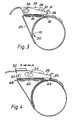
- Figure 3 shows the first fastener in a closed position:
- Figure 4 shows the second fastener in a closed position clamped around an object:
- Figure 5 is a view similar to figure 4 showing the third fastener in the closed position:
- Figure 6 is an enlarged sectional view on the line 6.6 of figure 5.
- Referring first to Figure 1, a length of thin flexible material is formed into a loop having a first
inner end 10, extending beyond a fixed attachment hook 12 (and continuing clockwise) to asecond attachment point 14 where it may be rivetted or spot welded to the loop. - A toggle fastener comprises
attachment plate 22,lever 24 andhasp bail 26. The latter is generally U shaped to engage over thehook 12. - As seen in Figure 3, when the fastener is in the closed condition, the loop ends 10, 16 are substantially overlapped so as to ensure that an object being clamped is engaged about 360 degrees of periphery. Any inequality of pressure in clamping occurs at the
zone 30 where there is step owing to the overlapped layers of the band, and the dimension of that step depends upon the thickness of the strip used for the band. - In the figures 1 and 3 illustration, the band is sufficiently thick and rigid to be used as the
platform 18 without needing any stiffening on the interior of the triangle formed by theparts - The lever is pivoted on the axis of
pin 32 and the hasp bail on the axis ofpivot 34. The third axis is that of the connection of the hasp bail to the hook. It will be noted that in moving from the Figure 1 to Figure 3 position, the axis ofpin 32 moves from one side of a plane containing the axes ofpin 34 and of the engagement with thehook 36 to the other side of that plane to give the over-centre action previously referred to. - The fastener of Figures 1 and 3 may be adjustable to give different clamping pressures on the same nominal size by making the spacing between the
pins pin 34 extending inslots 38 in the sides of thelever 24 for that adjustment purpose. - The fastener shown in Figures 2 and 4 is generally similar. It differs particularly in being made from a very much thinner band material so that the platform for the attachment plate of the toggle fastener needs to be stiffened by the
component 42 located in the interior of the triangle and in compression between thepoints lug 48 apertured to align with aneye 50 in the side of the lever so that a locking pin or padlock can be inserted to hold the fastener in the locked condition: and a locking catch operated by amember 52 which is slidable in the direction fo the arrows A-A of Figure 4 to engage a hook not shown because it lies between the side walls of the lever in afurther locking slot 54 in thelug 48, so as to provide security against accidental operation and release of the fastener. - In making a fastener according to the alternative arrangement described herein, the band would at the
end 10 terminate in the vicinity of thehook 12, and for example could be formed directly into the hook instead of using a separate part fixed to the band. The opposite end of theband 16 would then continue in the loop so as to underly the hook. - In the case of Figure 2 and 4 the band is so thin that there is an imperceptible step in the overlapped position giving particularly uniform clamping pressure around the object, and it will be noted that such uniformity will be maintained even if the object is non-circular.
- The
point 44 may cause a binding or scuffing of the material being clamped as the fastener moves from the Figure 2 position to the Figure 4 position. This may be particularly or even exclusively the case where the band is of particularly thin and flexible material. It is preferred to use particularly thin and flexible material for the band in order to get good clamping even if the object is not truly circular. The binding or scuffing can be reduced by stiffening the thin material of the band by using a thicker shorterstiffening piece 60 as illustrated in Figure2 and 4. Such a piece is however optional and its use, or not, may depend upon the particular application of a fastener. Where it is employed, it will extend over a sufficient length so that it overlaps thepoint 44 even in the most open position of the fastener possible, i.e. that illustrated in Figure 2. At the opposite end it is conveniently fastened to the hook or like which provides the attachment point which engages with the hasp bail. - In the third fastener shown in Figures 5-6 the construction is generally the same as in Figures 2 and 4 except that the
optional stiffener 60 is replaced by a channel section (and essential)stiffeners 64 which is fixed to the hook and to the flexible band. This channel serves to receive and locate the outer end of the band between its side walls whilst the inner end of theband 68 lies under the end of the channel. - Locating the toggle fastener generally tangentially of the loop ensures that the clamping force provided does not have any distorting effect on the loop causing localised unbalanced pressures.
Claims (6)
Applications Claiming Priority (2)
| Application Number | Priority Date | Filing Date | Title |
|---|---|---|---|
| GB8609568 | 1986-04-18 | ||
| GB868609568A GB8609568D0 (en) | 1986-04-18 | 1986-04-18 | Fasteners |
Publications (2)
| Publication Number | Publication Date |
|---|---|
| EP0242969A1 EP0242969A1 (en) | 1987-10-28 |
| EP0242969B1 true EP0242969B1 (en) | 1989-08-16 |
Family
ID=10596476
Family Applications (1)
| Application Number | Title | Priority Date | Filing Date |
|---|---|---|---|
| EP19870302188 Expired EP0242969B1 (en) | 1986-04-18 | 1987-03-13 | Fasteners |
Country Status (3)
| Country | Link |
|---|---|
| EP (1) | EP0242969B1 (en) |
| DE (1) | DE3760459D1 (en) |
| GB (1) | GB8609568D0 (en) |
Family Cites Families (4)
| Publication number | Priority date | Publication date | Assignee | Title |
|---|---|---|---|---|
| US2331132A (en) * | 1943-03-17 | 1943-10-05 | Nadelson Samuel | Hose clamp |
| DE1808165U (en) * | 1959-12-21 | 1960-03-17 | Heinrich Droege | HOSE CLAMP. |
| US3547510A (en) * | 1968-01-26 | 1970-12-15 | Philips Corp | Holographic image system and method employing narrow strip holograms |
| GB1250056A (en) * | 1968-04-16 | 1971-10-20 | Formica Corp | Decorative laminate having adherable coating thereon |
-
1986
- 1986-04-18 GB GB868609568A patent/GB8609568D0/en active Pending
-
1987
- 1987-03-13 EP EP19870302188 patent/EP0242969B1/en not_active Expired
- 1987-03-13 DE DE8787302188T patent/DE3760459D1/en not_active Expired
Also Published As
| Publication number | Publication date |
|---|---|
| DE3760459D1 (en) | 1989-09-21 |
| EP0242969A1 (en) | 1987-10-28 |
| GB8609568D0 (en) | 1986-05-21 |
Similar Documents
| Publication | Publication Date | Title |
|---|---|---|
| US4742600A (en) | Band clamp | |
| US4546524A (en) | Hose clamp apparatus | |
| US4382570A (en) | Draw band line support | |
| US11090060B2 (en) | Tourniquet with lever tensioning mechanism | |
| US9254778B2 (en) | Adjustable cam buckle | |
| US4660870A (en) | Clamp | |
| EP3266335A1 (en) | Wristwatch | |
| KR20010102532A (en) | Protecting cap for a right angle grinder | |
| EP0704033A1 (en) | A method and a fastening device for determining the position of a pipe, a hose or a similar element | |
| MXPA01010901A (en) | A closure casing. | |
| EP0242969A1 (en) | Fasteners | |
| MXPA96005959A (en) | Wheel fixing direction | |
| US5398385A (en) | Cargo transport accessory | |
| US2392210A (en) | Hose clamp | |
| US4558493A (en) | Variably accessible band clamp | |
| JP2614273B2 (en) | Closure for cable connection | |
| US5180124A (en) | Articulated clamp for fastening pipes | |
| JP4610756B2 (en) | Belt fastener | |
| JPS63247108A (en) | Non-slip tightening device for tire | |
| EP0369698B1 (en) | Improvements in or relating to buckles or securing straps | |
| US20260123938A1 (en) | Tourniquet with optimized inner strap and windlass | |
| JP2529514B2 (en) | Flange protector with integrated connector | |
| US5331722A (en) | Strap tensioning system | |
| JPH071578Y2 (en) | Emergency disconnection device for fluid handling equipment | |
| JPS587122Y2 (en) | bondage belt |
Legal Events
| Date | Code | Title | Description |
|---|---|---|---|
| PUAI | Public reference made under article 153(3) epc to a published international application that has entered the european phase |
Free format text: ORIGINAL CODE: 0009012 |
|
| AK | Designated contracting states |
Kind code of ref document: A1 Designated state(s): DE FR GB |
|
| 17P | Request for examination filed |
Effective date: 19880229 |
|
| 17Q | First examination report despatched |
Effective date: 19880915 |
|
| GRAA | (expected) grant |
Free format text: ORIGINAL CODE: 0009210 |
|
| AK | Designated contracting states |
Kind code of ref document: B1 Designated state(s): DE FR GB |
|
| REF | Corresponds to: |
Ref document number: 3760459 Country of ref document: DE Date of ref document: 19890921 |
|
| ET | Fr: translation filed | ||
| PLBE | No opposition filed within time limit |
Free format text: ORIGINAL CODE: 0009261 |
|
| STAA | Information on the status of an ep patent application or granted ep patent |
Free format text: STATUS: NO OPPOSITION FILED WITHIN TIME LIMIT |
|
| 26N | No opposition filed | ||
| PGFP | Annual fee paid to national office [announced via postgrant information from national office to epo] |
Ref country code: GB Payment date: 20000303 Year of fee payment: 14 |
|
| PGFP | Annual fee paid to national office [announced via postgrant information from national office to epo] |
Ref country code: DE Payment date: 20000313 Year of fee payment: 14 |
|
| PGFP | Annual fee paid to national office [announced via postgrant information from national office to epo] |
Ref country code: FR Payment date: 20000330 Year of fee payment: 14 |
|
| PG25 | Lapsed in a contracting state [announced via postgrant information from national office to epo] |
Ref country code: GB Free format text: LAPSE BECAUSE OF NON-PAYMENT OF DUE FEES Effective date: 20010313 |
|
| GBPC | Gb: european patent ceased through non-payment of renewal fee |
Effective date: 20010313 |
|
| PG25 | Lapsed in a contracting state [announced via postgrant information from national office to epo] |
Ref country code: FR Free format text: LAPSE BECAUSE OF NON-PAYMENT OF DUE FEES Effective date: 20011130 |
|
| REG | Reference to a national code |
Ref country code: FR Ref legal event code: ST |
|
| PG25 | Lapsed in a contracting state [announced via postgrant information from national office to epo] |
Ref country code: DE Free format text: LAPSE BECAUSE OF NON-PAYMENT OF DUE FEES Effective date: 20020101 |