EP0242943B1 - Improvements in or relating to road sweeping vehicles - Google Patents
Improvements in or relating to road sweeping vehicles Download PDFInfo
- Publication number
- EP0242943B1 EP0242943B1 EP87301113A EP87301113A EP0242943B1 EP 0242943 B1 EP0242943 B1 EP 0242943B1 EP 87301113 A EP87301113 A EP 87301113A EP 87301113 A EP87301113 A EP 87301113A EP 0242943 B1 EP0242943 B1 EP 0242943B1
- Authority
- EP
- European Patent Office
- Prior art keywords
- fan
- engine
- fluid coupling
- road sweeping
- flywheel
- Prior art date
- Legal status (The legal status is an assumption and is not a legal conclusion. Google has not performed a legal analysis and makes no representation as to the accuracy of the status listed.)
- Expired - Lifetime
Links
Images
Classifications
-
- E—FIXED CONSTRUCTIONS
- E01—CONSTRUCTION OF ROADS, RAILWAYS, OR BRIDGES
- E01H—STREET CLEANING; CLEANING OF PERMANENT WAYS; CLEANING BEACHES; DISPERSING OR PREVENTING FOG IN GENERAL CLEANING STREET OR RAILWAY FURNITURE OR TUNNEL WALLS
- E01H1/00—Removing undesirable matter from roads or like surfaces, with or without moistening of the surface
- E01H1/08—Pneumatically dislodging or taking-up undesirable matter or small objects; Drying by heat only or by streams of gas; Cleaning by projecting abrasive particles
- E01H1/0827—Dislodging by suction; Mechanical dislodging-cleaning apparatus with independent or dependent exhaust, e.g. dislodging-sweeping machines with independent suction nozzles ; Mechanical loosening devices working under vacuum
Definitions
- This invention relates to road sweeping vehicles of the suction type.
- Such vehicles are known in which an exhauster fan generates a vacuum within an air tight container mounted on the vehicle chassis and debris from the road is sucked through suction conduits connected to the container.
- an auxiliary engine is provided for driving the suction fan and sweeping machinery.
- GB-A-2095727 discloses a typical self-propelled road sweeper having all the features mentioned above.
- the fan and engine of most road sweepers are typically connected by a drive train which includes a centrifugal clutch or drive belts or rubber couplings.
- the fan and engine of GB-A-2095727 are coupled by a resilient mechanical coupling.
- a problem exists with such drive trains in that they possess elastic properties which can result in torsional vibration excited by the engine's torsional and cyclic vibration characteristics particularly during acceleration or deceleration of the drive when critical speeds may be endured. Consequently it has been found that in order to reduce vibration and the effects of shock it has been necessary to use a fan with a lowest moment of inertia practicable. Sincethefan is subjected in use to impacts and erosion from particles of debris there have been difficulties in achieving fan constructions which are both sufficiently robust and sufficiently low in moment of inertia.
- DE-A-2536031 discloses a driving mechanism having a drive part and a driven part with a shear- type fluid coupling therebetween. In such a coupling the fluid therebetween constitutes the sole bearing for the drive part.
- a suction type road sweeping vehicle comprising a self propelled chassis, an air tight container mounted on the chassis, at least one suction conduit connected to the container, a fan for generating a vacuum in the container by extracting air through an outlet duct, an engine having a flywheel connected to an output shaft for driving the fan and a drive train communicating between the engine and the fan, characterised inhat the drive train includes a fluid coupling, and the fluid coupling and the engine flywheel are of integral construction.
- An advantage of using afluid coupling is that it is substantially free of elastic properties in transmitting torsional drive and also such couplings have a considerable affinity for absorbing torsional shock.
- the drive train comprises a fluid coupling within the engine flywheel, an output shaft of the coupling connected to the input of a step up gearbox and an output shaft of the gearbox connected to the fan.
- the fluid coupling and the gearbox are housed in a common housing connected to the engine.
- the moment of inertia of the fan is substantially greater than that of the flywheel.
- the fluid coupling provides slippage in the drive train of not more than 5% under conditions of maximum drive speed.
- the vehicle includes access ports through which the fluid level in the fluid coupling may be externally monitored.
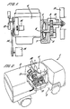
- the road sweeping vehicle 1 of Figure 2 comprises a self propelled chassis 2 on which is carried an air tight container 3.
- An auxiliary engine 4 is mounted on the chassis 2 for driving a suction fan and sweeping machinery.
- Suction conduits (not shown) beneath the vehicle operate in conjunction with the sweeping machinery to collect debris which is sucked into the container 3.
- FIG. 1 shows the engine 4 which is a four cylinder diesel engine having a flywheel 5 connected to the engine's output shaft 6.
- a fluid coupling 7 within the flywheel 5 couples the drive from the flywheel 5 to a gearbox input shaft 8 of a step up gearbox 9 having an output shaft 10 driving a centrifugal fan 11.
- the engine 4 also drives a conventional engine cooling fan 12 providing airflowthrough a radiator 13 as shown in Figure 2.
- the engine also has a pulley drive 14 for driving a water pump 15 supplying water for dust suppression sprays around the sweep gear (not shown).
- a hydraulic pump 16 is driven by the engine's power-take-off facility and this provides hydraulic power to the sweep gear.
- the centrifugal fan 11 is located in a fan housing 17 and expels air from the container 3 through an outlet duct 18.
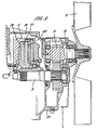
- a flywheel housing 19 contains the flywheel 5 which has an oil filled chamber 20 within which a driven plate 21 of the fluid coupling 7 is rotatable. Torque for the engine is transmitted across an oil filled interface 22 from the flywheel 5 to the driven plate 21 so as to drive the gearbox input shaft8 which is splined to the driven plate 21.
- the flywheel housing 19 is extended by a gearbox housing 23 containing a step up gearbox 9 having an output shaft 10 on which is mounted the centrifugal fan 11.
- a fan of 725mm diameter and 80mm depth includes 16 blades.
- the drive train and the fan are live mounted whilst the radiator 13, the fan housing 17 and the water pump 15 are separately mounted away from the engine.
- the fan 11 Since the fan 11 will encounter impacts and abrasion from residual debris in the exhausted air, the fan can now be of an advantageously heavy duty construction with self cleaning abrasion resistant blades due to the fact that the fan design is no longer subject to the constraint of moment of inertia matching to the engine's torsional and cyclic vibration characteristics.
Description
- This invention relates to road sweeping vehicles of the suction type.
- Such vehicles are known in which an exhauster fan generates a vacuum within an air tight container mounted on the vehicle chassis and debris from the road is sucked through suction conduits connected to the container. In addition to the propulsion unit of the vehicle an auxiliary engine is provided for driving the suction fan and sweeping machinery.
- GB-A-2095727 discloses a typical self-propelled road sweeper having all the features mentioned above.
- The fan and engine of most road sweepers are typically connected by a drive train which includes a centrifugal clutch or drive belts or rubber couplings. The fan and engine of GB-A-2095727 are coupled by a resilient mechanical coupling. A problem exists with such drive trains in that they possess elastic properties which can result in torsional vibration excited by the engine's torsional and cyclic vibration characteristics particularly during acceleration or deceleration of the drive when critical speeds may be endured. Consequently it has been found that in order to reduce vibration and the effects of shock it has been necessary to use a fan with a lowest moment of inertia practicable. Sincethefan is subjected in use to impacts and erosion from particles of debris there have been difficulties in achieving fan constructions which are both sufficiently robust and sufficiently low in moment of inertia.
- DE-A-2536031 discloses a driving mechanism having a drive part and a driven part with a shear- type fluid coupling therebetween. In such a coupling the fluid therebetween constitutes the sole bearing for the drive part.
- According to the present invention there is disclosed a suction type road sweeping vehicle comprising a self propelled chassis, an air tight container mounted on the chassis, at least one suction conduit connected to the container, a fan for generating a vacuum in the container by extracting air through an outlet duct, an engine having a flywheel connected to an output shaft for driving the fan and a drive train communicating between the engine and the fan, characterised inhat the drive train includes a fluid coupling, and the fluid coupling and the engine flywheel are of integral construction.
- An advantage of using afluid coupling is that it is substantially free of elastic properties in transmitting torsional drive and also such couplings have a considerable affinity for absorbing torsional shock.
- Conveniently the drive train comprises a fluid coupling within the engine flywheel, an output shaft of the coupling connected to the input of a step up gearbox and an output shaft of the gearbox connected to the fan.
- Conveniently the fluid coupling and the gearbox are housed in a common housing connected to the engine.
- It is possible to construct a fan of a more robust design than has been hitherto possible without incurring the penalty of vibration or shock damage to the drive train.
- Preferably the moment of inertia of the fan is substantially greater than that of the flywheel.
- Preferably the fluid coupling provides slippage in the drive train of not more than 5% under conditions of maximum drive speed.
- Conveniently the vehicle includes access ports through which the fluid level in the fluid coupling may be externally monitored. An advantage of this is that the drive train components need only be separated when major overhaul is required and routine maintenance will generally be limited to checking the fluid level through an access port.
- A specific embodiment of the invention will now be described by way of example only and with reference to the accompanying drawings of which
- Figure 1 is a schematic sectional elevation of the engine, drive train and fan of a road sweeping vehicle,
- Figure 2 is a schematic perspective part cut- away view of a road sweeping vehicle and
- Figure 3 is a sectional elevation showing details of the drive train of Figure 1.
- The road sweeping vehicle 1 of Figure 2 comprises a self propelled chassis 2 on which is carried an air tight container 3. An auxiliary engine 4 is mounted on the chassis 2 for driving a suction fan and sweeping machinery. Suction conduits (not shown) beneath the vehicle operate in conjunction with the sweeping machinery to collect debris which is sucked into the container 3.
- Figure 1 shows the engine 4 which is a four cylinder diesel engine having a
flywheel 5 connected to the engine's output shaft 6. A fluid coupling 7 within theflywheel 5 couples the drive from theflywheel 5 to a gearbox input shaft 8 of a step up gearbox 9 having anoutput shaft 10 driving a centrifugal fan 11. - The engine 4 also drives a conventional engine cooling fan 12 providing airflowthrough a radiator 13 as shown in Figure 2. The engine also has a
pulley drive 14 for driving a water pump 15 supplying water for dust suppression sprays around the sweep gear (not shown). Ahydraulic pump 16 is driven by the engine's power-take-off facility and this provides hydraulic power to the sweep gear. - The centrifugal fan 11 is located in a
fan housing 17 and expels air from the container 3 through an outlet duct 18. - In Figure 3 a
flywheel housing 19 contains theflywheel 5 which has an oil filledchamber 20 within which a drivenplate 21 of the fluid coupling 7 is rotatable. Torque for the engine is transmitted across an oil filledinterface 22 from theflywheel 5 to the drivenplate 21 so as to drive the gearbox input shaft8 which is splined to the drivenplate 21. - The
flywheel housing 19 is extended by agearbox housing 23 containing a step up gearbox 9 having anoutput shaft 10 on which is mounted the centrifugal fan 11. - Upon starting the engine 4thefiywheei 5 rotates and torque is transmitted to the driven
plate 21 across the oil filledinterface 22. Drive is transmitted to the centrifugal fan 11 which begins to rotate. Some slippage in the drive train comprising theflywheel 5, fluid coupling 7 and gearbox 9 is experienced particularly at engine idling speeds due to the inherent properties of the fluid coupling. However as the engine is accelerated tc full power the torque transmitted by the fluid coupling 7 is such that slippage is reduced to less than 5%. - In a particular example a fan of 725mm diameter and 80mm depth includes 16 blades. A engine speeds of 1500 rpm and 1800 rpm the fan speed was greater than 2620 rpm and 3150 rpm respectively using a gearbox ratio of 1:1.79. This represents a nominal slippage of 2.5%.
- To reduce the effects of engine vibration to a minimum only the engine, the drive train and the fan are live mounted whilst the radiator 13, the
fan housing 17 and the water pump 15 are separately mounted away from the engine. - Since the fan 11 will encounter impacts and abrasion from residual debris in the exhausted air, the fan can now be of an advantageously heavy duty construction with self cleaning abrasion resistant blades due to the fact that the fan design is no longer subject to the constraint of moment of inertia matching to the engine's torsional and cyclic vibration characteristics.
Claims (6)
Applications Claiming Priority (2)
| Application Number | Priority Date | Filing Date | Title |
|---|---|---|---|
| GB8609016A GB2188963B (en) | 1986-04-14 | 1986-04-14 | Improvements in or relating to road sweeping vehicles |
| GB8609016 | 1986-04-14 |
Publications (3)
| Publication Number | Publication Date |
|---|---|
| EP0242943A2 EP0242943A2 (en) | 1987-10-28 |
| EP0242943A3 EP0242943A3 (en) | 1988-07-20 |
| EP0242943B1 true EP0242943B1 (en) | 1990-12-27 |
Family
ID=10596138
Family Applications (1)
| Application Number | Title | Priority Date | Filing Date |
|---|---|---|---|
| EP87301113A Expired - Lifetime EP0242943B1 (en) | 1986-04-14 | 1987-02-09 | Improvements in or relating to road sweeping vehicles |
Country Status (4)
| Country | Link |
|---|---|
| US (1) | US4773119A (en) |
| EP (1) | EP0242943B1 (en) |
| DE (1) | DE3767012D1 (en) |
| GB (1) | GB2188963B (en) |
Families Citing this family (11)
| Publication number | Priority date | Publication date | Assignee | Title |
|---|---|---|---|---|
| GB2276853A (en) * | 1993-03-23 | 1994-10-12 | Johnston Eng Ltd | Exhauster fan system for road-sweeping vehicles |
| US6615443B2 (en) * | 2001-04-04 | 2003-09-09 | Mohawk Milling & Sweeping Corp. | Stall converter for single engine sweeper |
| US7600289B2 (en) * | 2002-12-23 | 2009-10-13 | Hydramaster North America, Inc. | Three-point mount for an industrial carpet cleaner |
| US7208050B2 (en) * | 2002-12-23 | 2007-04-24 | Hydramaster Corporation | Direct drive industrial carpet cleaner |
| DE102011016204A1 (en) * | 2011-04-06 | 2012-10-11 | Man Truck & Bus Ag | Drive system of engine cooling for motor vehicles |
| US9010467B2 (en) | 2012-04-23 | 2015-04-21 | Federal Signal Corporation | Shared power street sweeper |
| US20140102432A1 (en) * | 2012-10-16 | 2014-04-17 | Diamond Products, Limited | Cooling System For Concrete Saw |
| GB2523765B (en) * | 2014-03-04 | 2016-09-28 | Johnston Sweepers Ltd | Powertrain for a road cleaning vehicle |
| AU2016200049B2 (en) | 2015-01-06 | 2020-01-02 | Techtronic Industries Co., Ltd. | Axial blower vacuum |
| MX2017014107A (en) * | 2015-05-19 | 2018-03-16 | Horton Inc | Angled torque transmission system and method. |
| DE102018104116B3 (en) | 2018-02-23 | 2019-08-08 | Aebi Schmidt Deutschland Gmbh | sweeper |
Family Cites Families (4)
| Publication number | Priority date | Publication date | Assignee | Title |
|---|---|---|---|---|
| US3172143A (en) * | 1962-10-29 | 1965-03-09 | Yucis | Machine for cleaning large surface areas |
| DE2536031A1 (en) * | 1975-08-13 | 1977-02-24 | Smiths Industries Ltd | Drive mechanism - has drive and driven mechanism with shear type fluid coupling inbetween |
| AU6413580A (en) * | 1979-11-17 | 1981-05-21 | Hestair Eagle Ltd. | Suction operated refuse collecting apparatus |
| GB2095727B (en) * | 1981-03-28 | 1984-08-01 | Hestair Eagle Ltd | Refuse collecting apparatus |
-
1986
- 1986-04-14 GB GB8609016A patent/GB2188963B/en not_active Expired
-
1987
- 1987-02-09 DE DE8787301113T patent/DE3767012D1/en not_active Expired - Lifetime
- 1987-02-09 EP EP87301113A patent/EP0242943B1/en not_active Expired - Lifetime
- 1987-04-14 US US07/038,533 patent/US4773119A/en not_active Expired - Lifetime
Also Published As
| Publication number | Publication date |
|---|---|
| EP0242943A3 (en) | 1988-07-20 |
| GB8609016D0 (en) | 1986-05-21 |
| GB2188963A (en) | 1987-10-14 |
| EP0242943A2 (en) | 1987-10-28 |
| DE3767012D1 (en) | 1991-02-07 |
| US4773119A (en) | 1988-09-27 |
| GB2188963B (en) | 1989-11-22 |
Similar Documents
| Publication | Publication Date | Title |
|---|---|---|
| EP0242943B1 (en) | Improvements in or relating to road sweeping vehicles | |
| AU597276B2 (en) | Electric wheel drive | |
| EP0024373B2 (en) | Motorized two-wheeled vehicle power transmission casings | |
| EP0173301B1 (en) | Sweeper with speed control for brush and vacuum fan | |
| KR101127200B1 (en) | Propulsion power transmission device with a hydrodynamic reverse clutch | |
| US6269713B1 (en) | Vehicle with auxiliary traveling device | |
| US5419006A (en) | Exhauster fan systems | |
| US6615443B2 (en) | Stall converter for single engine sweeper | |
| JPH0626932B2 (en) | Electric wheel drive device | |
| KR20190031127A (en) | Road Surface Cleaning Vechicle Equipped With Auxiliary Power Unit And Clutch | |
| EP0347142A1 (en) | Road-sweeping vehicle | |
| EP1488124B1 (en) | Hydrodynamic coupling | |
| US20220316160A1 (en) | Single engine sweeper system with improved pump mounting mechanism | |
| GB2095727A (en) | Refuse collecting apparatus | |
| CN208982643U (en) | A kind of anti-vehicle reduction gearbox of permanent magnetic coupling | |
| KR200198211Y1 (en) | A coupling device for power transmission having a double attenuation structure | |
| SU458633A1 (en) | Manual cleaning machine | |
| WO2019180409A1 (en) | Mobile vacuum excavator and associated methods | |
| CN109811693A (en) | A kind of sweeping machine slave speed-limiting protective device | |
| CN109372634A (en) | Diesel engine flywheel air exhauster | |
| JPS60137336A (en) | Electric cleaner | |
| CS235147B1 (en) | Arrangement of cooling system's fan baffle's co-axial hydrodrive with self-propelled working machines | |
| JPS59176404A (en) | Method of driving generator by turning device with main engine | |
| JPH0974856A (en) | Riding mower | |
| CN106087834A (en) | A kind of sweeping machine slave speed-limiting protective device |
Legal Events
| Date | Code | Title | Description |
|---|---|---|---|
| PUAI | Public reference made under article 153(3) epc to a published international application that has entered the european phase |
Free format text: ORIGINAL CODE: 0009012 |
|
| AK | Designated contracting states |
Kind code of ref document: A2 Designated state(s): DE FR NL |
|
| PUAL | Search report despatched |
Free format text: ORIGINAL CODE: 0009013 |
|
| AK | Designated contracting states |
Kind code of ref document: A3 Designated state(s): DE FR NL |
|
| 17P | Request for examination filed |
Effective date: 19880905 |
|
| 17Q | First examination report despatched |
Effective date: 19891005 |
|
| GRAA | (expected) grant |
Free format text: ORIGINAL CODE: 0009210 |
|
| AK | Designated contracting states |
Kind code of ref document: B1 Designated state(s): DE FR NL |
|
| REF | Corresponds to: |
Ref document number: 3767012 Country of ref document: DE Date of ref document: 19910207 |
|
| ET | Fr: translation filed | ||
| PLBE | No opposition filed within time limit |
Free format text: ORIGINAL CODE: 0009261 |
|
| STAA | Information on the status of an ep patent application or granted ep patent |
Free format text: STATUS: NO OPPOSITION FILED WITHIN TIME LIMIT |
|
| 26N | No opposition filed | ||
| PGFP | Annual fee paid to national office [announced via postgrant information from national office to epo] |
Ref country code: NL Payment date: 20060131 Year of fee payment: 20 Ref country code: DE Payment date: 20060131 Year of fee payment: 20 |
|
| PGFP | Annual fee paid to national office [announced via postgrant information from national office to epo] |
Ref country code: FR Payment date: 20060222 Year of fee payment: 20 |
|
| PG25 | Lapsed in a contracting state [announced via postgrant information from national office to epo] |
Ref country code: NL Free format text: LAPSE BECAUSE OF EXPIRATION OF PROTECTION Effective date: 20070209 |
|
| NLV7 | Nl: ceased due to reaching the maximum lifetime of a patent |
Effective date: 20070209 |