EP0242929A2 - Vorrichtung zur Herstellung von Teigkugeln für Bäckereiprodukte - Google Patents
Vorrichtung zur Herstellung von Teigkugeln für Bäckereiprodukte Download PDFInfo
- Publication number
- EP0242929A2 EP0242929A2 EP87200751A EP87200751A EP0242929A2 EP 0242929 A2 EP0242929 A2 EP 0242929A2 EP 87200751 A EP87200751 A EP 87200751A EP 87200751 A EP87200751 A EP 87200751A EP 0242929 A2 EP0242929 A2 EP 0242929A2
- Authority
- EP
- European Patent Office
- Prior art keywords
- bearing surface
- base
- dough
- ball
- counter
- Prior art date
- Legal status (The legal status is an assumption and is not a legal conclusion. Google has not performed a legal analysis and makes no representation as to the accuracy of the status listed.)
- Withdrawn
Links
- 235000015173 baked goods and baking mixes Nutrition 0.000 title claims abstract description 4
- 230000033001 locomotion Effects 0.000 claims abstract description 9
- 230000005540 biological transmission Effects 0.000 claims description 2
- 238000004519 manufacturing process Methods 0.000 description 3
- 230000006835 compression Effects 0.000 description 1
- 238000007906 compression Methods 0.000 description 1
- 230000000694 effects Effects 0.000 description 1
- 230000002349 favourable effect Effects 0.000 description 1
- 230000005484 gravity Effects 0.000 description 1
- 238000005303 weighing Methods 0.000 description 1
Images

Classifications
-
- A—HUMAN NECESSITIES
- A21—BAKING; EDIBLE DOUGHS
- A21C—MACHINES OR EQUIPMENT FOR MAKING OR PROCESSING DOUGHS; HANDLING BAKED ARTICLES MADE FROM DOUGH
- A21C7/00—Machines which homogenise the subdivided dough by working other than by kneading
Definitions
- This invention relates to a device to prepare a dough ball for bakery products, said device consisting substantially of a base provided with a bearing surface for supporting a portion of dough to be formed into a ball, and a counter member arranged on the bearing surface, in which at least the base can be brought into an oscillating motion by means of a drive.
- Devices of the kind are known in numerous embodiments, their capacity being such that large quantities of dough must be processed in order to permit the device to operate at an economic level.
- a device of the kind is thus serviceable only in a production process which involves relatively large quantities of dough.
- the invention has for its aim to provide a device in which the quantity of dough can be arbitrarily determined, and can even be limited to a single ball.
- the device is therefore suitable for relatively small bakeries, and can be deployed flexibly in the production process.
- the device according to the invention is distinguished , in that the bearing surface is placed in a position which deviates from the horizontal and in that the counter-element is a curved wall which makes close contact with at least the bottom boundary of the bearing surface.
- the counter-element can be made bowl i shaped, it being thereby advantageous to arrange the bowl on a frame which can be hinged around its horizontal axis.
- the bowl can be swung up from the bearing surface or base so that the completed dough ball can slide down the bearing surface and can be removed. In this way, the device can be automated with respect to forming time.
- the bearing surface is provided with one or more irregularities, preferably in the form of one or more spiral grooves.
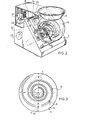
- Numeral 1 indicates a casing-like chassis of the device.
- the front of casing-like chassis 1 is made with a sloping front surface 2 in which an opening 3 is cut.
- a drive mechanism 5 4 which consists of a motor 5 driving, through a worm-gear transmission 6, a rotational shaft 7 which is arranged perpendicular to front wall 2.
- the rotation shaft is journalled in a ball-bearing 8, which is mounted in a bracket 9 extending between the upright side walls of case 1. This is merely for illustration and the journalling of shaft 7 can take place in any arbitrary manner.
- a base 11 Parallel to and outside front wall 2, a base 11 is arranged, made with a bush 12 on its underside. In this bush 12 is mounted a bearing 13 which fits around eccentric disc 10.
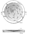
- the base 11 has a disc-like shape (see also figure 3) and is made on the side of bush 12 with a radially oriented groove 14. Into this groove 14 projects a pin 15, which is mounted on fixed front wall 2.
- Base 11 displays a front surface 16 which is the non- horizontal bearing surface according the invention.
- This bearing surface is made with irregularities, as shown in figure 3, preferably in the form of spiral grooves 17.
- this bearing surface contact is made with a curved wall 18, which is a part of a whole bowl-shaped component, of which the top is made as a supply funnel 19.
- the counter-member in the form of a bowl 18 shown in the drawing is, on the side opposite supply funnel 19, which side makes contact with base 11, supported on a frame 20.
- This frame 20 has a circular opening 21 along the edge of which the wall of bowl 18 is adjoined.
- Frame 20 is provided with two upward-pointing arms 22 each of which is provided with a hole, in such manner that a hinge pin or axle 23 can be fastened through the holes of arms 22.
- This hinge axle 23 is journalled in bearing brackets 24 arranged on front wall 2 of case 1, in such manner that frame 20 can be hinged upwards around axis 23.
- hinge axle 23 is provided with a thereto firmly affixed lever arm 25.
- lever arm 25 Between lever arm 25 and the top wall of case 1, a compression spring 26 is arranged.
- the end of lever arm 25 which is distal from hinge axis 23 is of such material that it can be attracted by solenoid coil 27, arranged above it and fixed firmly to the top wall of case 1.
- Solenoid coil 27 can be powered in a not further indicated but known manner.
- the powering of the solenoid can be interrupted by means of a so-called time switch 28, such that the solenoid core loses its magnetic attractive force upon interruption of the electric tension.
- the piece of dough D is turned around in bowl 18 and formed into a ball. This effect is promoted by the spiral grooves 17.
- the device is then ready for the following dough- forming operation, for which the baker turns bowl 18 back into its original position, can power up the solenoid and can place i a new piece of dough in the bowl.
- Figures 4 and 5 show an alternative embodiment of the base, in which the upper surface of the base is hollowed into a dish shape, the bearing surface thus formed being deepened in a stepped fashion towards the centre, whereby a favourable action is obtained on the dough to be shaped.
- the invention is not limited to the above-described embodiment.
- base 11 a non-circular form. such as an elongated ellipse of which the principal axis extends in a horizontal direction, the counter-element displaying a curved wall with a plurality of adjacent bowl-shaped parts 18.
- the capacity of the device can be simply expanded.
Landscapes
- Life Sciences & Earth Sciences (AREA)
- Engineering & Computer Science (AREA)
- Food Science & Technology (AREA)
- Food-Manufacturing Devices (AREA)
- Manufacturing And Processing Devices For Dough (AREA)
Applications Claiming Priority (2)
| Application Number | Priority Date | Filing Date | Title |
|---|---|---|---|
| NL8600995A NL8600995A (nl) | 1986-04-18 | 1986-04-18 | Inrichting voor het vervaardigen van een deegbol voor bakprodukten. |
| NL8600995 | 1986-04-18 |
Publications (2)
| Publication Number | Publication Date |
|---|---|
| EP0242929A2 true EP0242929A2 (de) | 1987-10-28 |
| EP0242929A3 EP0242929A3 (de) | 1989-03-22 |
Family
ID=19847898
Family Applications (1)
| Application Number | Title | Priority Date | Filing Date |
|---|---|---|---|
| EP87200751A Withdrawn EP0242929A3 (de) | 1986-04-18 | 1987-04-21 | Vorrichtung zur Herstellung von Teigkugeln für Bäckereiprodukte |
Country Status (2)
| Country | Link |
|---|---|
| EP (1) | EP0242929A3 (de) |
| NL (1) | NL8600995A (de) |
Family Cites Families (4)
| Publication number | Priority date | Publication date | Assignee | Title |
|---|---|---|---|---|
| DE235465C (de) * | ||||
| FR937735A (fr) * | 1946-06-14 | 1948-08-25 | Machine à manier la pâte | |
| FR947648A (fr) * | 1947-05-20 | 1949-07-07 | Machine à manier le pain | |
| NL6511480A (de) * | 1965-09-02 | 1967-03-03 |
-
1986
- 1986-04-18 NL NL8600995A patent/NL8600995A/nl not_active Application Discontinuation
-
1987
- 1987-04-21 EP EP87200751A patent/EP0242929A3/de not_active Withdrawn
Also Published As
| Publication number | Publication date |
|---|---|
| NL8600995A (nl) | 1987-11-16 |
| EP0242929A3 (de) | 1989-03-22 |
Similar Documents
| Publication | Publication Date | Title |
|---|---|---|
| US4765746A (en) | Dough kneader | |
| US2481010A (en) | Juicer for fruits and vegetables with vertical axis rotating grater plate | |
| US2253027A (en) | Toasting machine | |
| US4432544A (en) | Fishing toy | |
| CN111319967B (zh) | 一种取碗机 | |
| EP0242929A2 (de) | Vorrichtung zur Herstellung von Teigkugeln für Bäckereiprodukte | |
| JP2551976B2 (ja) | 調理用スライサ | |
| WO1992018043A1 (en) | Token- or coin-, or the like, operated apparatus for automatically frying eggs, in particular for canteens, institutions, and the like | |
| CN105366375A (zh) | 自动投料机构 | |
| US2775189A (en) | Wiener barbecuing machine | |
| CN217696097U (zh) | 一种炒菜机用食材盛放及快速投放装置 | |
| US4911284A (en) | Whisker driven conveyor system | |
| US2873047A (en) | Holder for drinking straws | |
| JPH075183B2 (ja) | パーツフィーダ | |
| CN215305074U (zh) | 一种调料下料装置及烹饪设备 | |
| CN223503890U (zh) | 收纳架 | |
| JPH01224036A (ja) | 自動飲料撹拌方法とその装置 | |
| US4021023A (en) | Automatic agitator for film development | |
| JP2022178729A (ja) | 搬送装置 | |
| CN216094148U (zh) | 一种可自动翻料的化工物料粉碎装置 | |
| CN114797082B (zh) | 手动升降骰子盘 | |
| US3977549A (en) | Construction for clearing tableware from trays | |
| CN109042871A (zh) | 一种谷物晾晒装置 | |
| EP0734659A2 (de) | Apfelschüttelausrichter | |
| US3032235A (en) | Dispenser container |
Legal Events
| Date | Code | Title | Description |
|---|---|---|---|
| PUAI | Public reference made under article 153(3) epc to a published international application that has entered the european phase |
Free format text: ORIGINAL CODE: 0009012 |
|
| AK | Designated contracting states |
Kind code of ref document: A2 Designated state(s): AT BE CH DE ES FR GB GR IT LI LU NL SE |
|
| 17P | Request for examination filed |
Effective date: 19880428 |
|
| PUAL | Search report despatched |
Free format text: ORIGINAL CODE: 0009013 |
|
| RHK1 | Main classification (correction) |
Ipc: A21C 7/04 |
|
| AK | Designated contracting states |
Kind code of ref document: A3 Designated state(s): AT BE CH DE ES FR GB GR IT LI LU NL SE |
|
| STAA | Information on the status of an ep patent application or granted ep patent |
Free format text: STATUS: THE APPLICATION IS DEEMED TO BE WITHDRAWN |
|
| 18D | Application deemed to be withdrawn |
Effective date: 19890925 |