EP0242838B1 - A heat exchange pipe for heat transfer - Google Patents
A heat exchange pipe for heat transfer Download PDFInfo
- Publication number
- EP0242838B1 EP0242838B1 EP87105810A EP87105810A EP0242838B1 EP 0242838 B1 EP0242838 B1 EP 0242838B1 EP 87105810 A EP87105810 A EP 87105810A EP 87105810 A EP87105810 A EP 87105810A EP 0242838 B1 EP0242838 B1 EP 0242838B1
- Authority
- EP
- European Patent Office
- Prior art keywords
- pipe
- flow
- baffle element
- heat exchange
- sections
- Prior art date
- Legal status (The legal status is an assumption and is not a legal conclusion. Google has not performed a legal analysis and makes no representation as to the accuracy of the status listed.)
- Expired
Links
Images


Classifications
-
- F—MECHANICAL ENGINEERING; LIGHTING; HEATING; WEAPONS; BLASTING
- F28—HEAT EXCHANGE IN GENERAL
- F28F—DETAILS OF HEAT-EXCHANGE AND HEAT-TRANSFER APPARATUS, OF GENERAL APPLICATION
- F28F9/00—Casings; Header boxes; Auxiliary supports for elements; Auxiliary members within casings
- F28F9/02—Header boxes; End plates
- F28F9/026—Header boxes; End plates with static flow control means, e.g. with means for uniformly distributing heat exchange media into conduits
- F28F9/028—Header boxes; End plates with static flow control means, e.g. with means for uniformly distributing heat exchange media into conduits by using inserts for modifying the pattern of flow inside the header box, e.g. by using flow restrictors or permeable bodies or blocks with channels
-
- F—MECHANICAL ENGINEERING; LIGHTING; HEATING; WEAPONS; BLASTING
- F28—HEAT EXCHANGE IN GENERAL
- F28F—DETAILS OF HEAT-EXCHANGE AND HEAT-TRANSFER APPARATUS, OF GENERAL APPLICATION
- F28F13/00—Arrangements for modifying heat-transfer, e.g. increasing, decreasing
- F28F13/06—Arrangements for modifying heat-transfer, e.g. increasing, decreasing by affecting the pattern of flow of the heat-exchange media
Definitions
- the invention relates to a heat exchange pipe according to the precharacterizing parts of claims 1 and 2.
- This kind of agents is to be re-cooled on more fields of the industry.
- the agents to be cooled are mixed of two components having different volatilities. These two phases differ not only in their state of aggregation but in their concentrations, too.
- the working agent having two phases is cooled, its temperature gets lower and, in the same time, dissolving and condensation occure. Since the two phases stream separately, they are not in a constant thermodynamic equilibrium and, therefore the component being less volatil condensates quicker, the condensate recooles quicker, and the component being more volatile and forming the bigger part of the gaseous phase dissolves later in the liquid phase.
- the temperature characteristics of the known heat exchange pipes in dependency of the amount of transferred heat are quite disadvantageous, thus, for a given thermodynamic process, a larger and more expensive heat-exchanger is required for providing the same thermodynamic coefficient.
- the already condensed working agent formes a liquid phase remaining on the inner surface of the pipe wall which hinders the heat transfer between the non-condensed steam phase and the wall of the pipe.
- the above mentioned ring-shaped flow pattern is quite similar to that of the viscous liquids used as working agents in heat exchange pipes.
- the composition of the agent itself having different compositions of different phases is inhomogeneous, and in the latter, the physical conditions (temperature and viscosity) are inhomogeneous to a great extent.
- oils which are used for the lubrication of the bearings of steam-turbines or gas-turbines and cooling thereof and which are cooled in heat exchangers to eliminate the heat arising from the mechanical heat-losses from the bearings are bad heat conductors and from laminarly in the pipes of the heat-exchangers.
- the inferior heat transfer coefficient of laminarly flowing oils with bad heat conductivity can be explained by the fact that the outer layer, having been cooled and flowing with a low velocity along the pipe surface, is acting as thermal insulation and hinders the path of the heat flux from the warmer oil towards the pipewall. While the outer cooled oil is flowing forward with a low velocity on the pipewall, forming a quasi dense layer on the pipewall, the warm oil flows in the middle of the pipe and it is hardly cooled. Heat is able to flow only by way of conductivity.
- longitudinally arranged inner ribs are used, which are parallel or substantially parallel to the longitudinal axis of the pipe. Essentially, the heat has to cover a shorter path in the cut-up cross-section, accordingly resistance will be also less.
- the disadvantage of the ribs is that resistance, weight and therefore cost of production of the heat-exchanger are also increased.
- a device for generating special turbulence patterns in fluids flowing in pipes is know from the US-PS 4 179 222. These devices made of metal sheets are inserted into a pipe and give the flow a component in radial direction additionally to the direction of the axis of the pipe. This causes turbulences and hence an improved heat transfer towards the wall of the pipe.
- the disadvantage of this turbulence generating device is, that there is no defined interchangement of the upper and the lower section of the flow or the middle section and the section near the wall of the pipe. Hence a defined interchangement of the gaseous with the liquid phase of a flow or of a liquid phase of higher viscosity with a liquid phase of lower viscosity is not possible by means of this device.
- a heat exchange pipe according to the precharacterizing part of claim 1 for heat transfer from a medium in the pipe is known from the GB-PS 2 135 439.
- This heat exchange pipe includes spaced- apart baffle elements disposed within the pipe substantially perpendicularly to the longitudinal axis of the pipe and which have means for deflecting the outer layer of the medium away from the wall of the pipe.
- the known baffle element has a ring surface being perpendicular to the wall which has to aid the deflecting action. But this ring surface causes a sharp change of the flow direction which increases the flow resistance within the pipe and, in the same time, it amplifies the tendency of the viscous liquid to by-pass the hindrance, i.e. the ring surface being in its flow path without any substantial change in its laminar flow pattern in the boundary layer.
- the known baffle element can only be used with said viscous liquids within certain speed and viscosity limits. It is not suitable for wavy flow patterns at all.
- the main object of this invention is to provide a heat exchange pipe according to the precharacterizing part of claims 1 and 2, increasing the efficiency of the heat transfer between practically any kind of flowing, inhomogenous working agent forming a wavy flow pattern or a ring-shaped flowing pattern with an outer agent.
- baffle element should be used within the pipe with which particles of the working agent having eminent importance with respect to the heat transfer coefficient should be transfered to a well defined portion of the pipe when seen in cross section of the pipe. Furthermore, the baffle element should be free of any sharp changes of the flow direction and it should be easy to manufacture and arrange it within the pipe.
- a surface area of the inlet of the first kind of channels equals that of their outlet.
- the deflecting channels of the baffle elements are free of any sharp directional change and have a constant curvature between the inlets and the outlets of the channels.
- the first portion of the cross-section is limited by the wall and a secant of the cross-section of the pipe and the second portion is limited by the wall and by another secant of the cross-section. Therein the first portion and the second portion are arranged in diametrically opposite positions and the secants are parallel to each other.
- the first portion of its cross-section is substantially ring-shaped and is partially limited by the wall of the pipe.
- the second portion of its cross-section has a disk-like shape and is arranged in a middle axis of the pipe, or that the second portion of its cross-section is prism-shaped, a middle axis of which coincides with a symmetry line of the cross-section.
- the second portion can be limited at least partially by the wall of the pipe.
- baffle elements are arranged in the pipe, and the angular dispositions and/or the constructions of the successive baffle elements are different.
- the baffle elements can be made of metal plates preferably by pressing. With this, its possible in this invention, that the baffle elements are assembled from at least two metal plates being previously formed by pressing for having identical shapes.
- the baffle elements are resiliently pressed against the inner wall of the pipe when arranged therein.
- the baffle elements can always be attached to a fixing wire which is fixed to the pipe.
- baffle element when a length of the baffle element measured in direction of the longitudinal axis of the pipe is maximally three- times larger than the diameter of the pipe. According to a further preferred embodiment a thickness of the metal plate material of the baffle elements is maximally one tenth of the diameter of the pipe. Finally, it is preferably if the flow channels within the baffle element have a helical design.
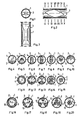
- FIGS 1 to 10 illustrate a first preferred embodiment of the heat exchange pipe 1 according to this invention.
- this embodiment can preferably be used for working agents which or the liquid phase of which forms a wavy flow pattern.
- This liquid phase is referred to by reference numeral 2 throughout the whole description.
- a baffle element 3 is arranged, which is shown in Figs. 4 to 10 always by a line showing the deflecting surface which is cut by the cutting plane generating the cross-sections.
- liquid phase 2 is lifted from a lower part of the cross-section of pipe 1 in fig. 4 to a higher part of it in Fig. 10.
- Baffle element 3 as shown in Fig. 4 is formed for exactly separating liquid phase 2 from a gaseous or steam phase 4 of the working agent streaming in pipe 1.
- liquid phase 2 and gaseous or steam phase 4 as shown in Fig. 4 correspond to an inlet of two separated channels of baffle element 3.
- each of phases 2 and 4 is in a closed channel, respectively.
- the outlets of the channels are shown in Fig. 10, that of liquid phase 2 in a higher portion of the cross-section in the height of which the inlet of the channel of gaseous or steam phase 4 (Fig. 15) is, and that of gaseous or steam portion 4 in a lower portion of the cross-section, in the height of which the inlet of the channel for liquid phase 2 (Fig.
- liquid phase 2 is in its whole amount separated from the wall of pipe 1 and it changes place with gaseous or steam phase 4.
- liquid phase 2 is again contacted with the inner wall of pipe 1 (see Figs. 8 to 10).
- heat exchange pipe 1 has a circular cross-section, wherein the deflecting surfaces at the inlet and the outlet of the channels are formed as secants of the circle which are parallel to each other.
- the surface areas determined by the secants and the inner wall of the pipe 1 for the channel of liquid phase 2 are equal at the inlet and at the outlet, respectively.
- the surface area of the outlet of the channel of the liquid phase 2 can be larger than the inlet and, with this, a continuously narrowing channel can be provided for gaseous or steam phase 4.
- the speed of this phase 4 will be enlargened and liquid phase 2 will be sucked on the outlet side of baffle element 3.
- This arrangement is very useful in applications wherein the liquid phase 2 has a relatively low streaming speed and the energy for its "lifting" must additionally be provided. Nevertheless, the latter embodiment raises the flow resistance, however, it could be necessary.
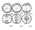
- Figs. 11 to 15 the same sequence of cross-sections is shown as of the previous embodiment, however, this embodiment can be used for the ring-shaped flow pattern, in the case of which liquid phase 2 is adhered to the wall of pipe 1 in a ring form.
- This embodiment differs from the previous one in that, too, that the channels are formed of two deflecting surfaces 6 and 7 which define a ring-shaped inlet opening, two separated deflecting channels and an outlet opening in the centre of pipe 1 for liquid phase 2.
- the inlet of the channel for phase 4 is in the centre of pipe 1, the deflecting channel is defined by deflecting surfaces 6 and 7 and the outlet is ring-shaped around the outlet of liquid phase 2.
- Figs. 16 to 20 another embodiment is shown for the same application. Therein, three deflecting surfaces 8, 9 and 10 are provided and arranged in a configuration of 120 degrees with respect to each other. They define three channels for liquid phase 2 having a common ring-shaped inlet and a common outlet in the centre of pipe 1.
- Figs. 21 to 29 illustrate an embodiment which is easy to manufacture.
- This embodiment corresponds to that shown in figs. 11 to 15 wherein baffle element 3 has two deflecting surfaces 6 and 7 which are formed, in this example, of metal sheets by pressing.
- Deflecting surfaces 6 and 7 have identical shapes and are arranged in, a face- to-face relationship. They define two channels for liquid phase 2 between the ring-shaped inlet and the outlet in the centre of pipe 1. Edges 11 and 12 of deflecting surfaces 6 and 7 contact the wall of pipe 1 in the whole length of baffle element 3.
- edges 11, 12 are contacted in tight relationship, so that liquid phase 2 having the ring-shaped flow pattern can only enter its channels between the wall of pipe 1 and deflecting surfaces 6 and 7. It will leave them at the outlet of the channels defined by deflecting surfaces 6 and 7 in the centre of pipe 1 as shown in Fig. 29.
- edges 11 of deflecting surface 6 and edges 12 of deflecting surface 7 are tightly connected to each other, respectively. In this way, the boundary layer of liquid phase 2 will totally be separated from the wall of pipe 1 and led through the channels into the centre of pipe 1.
- gaseous or steam phase 4 streaming in the middle of pipe 1 enters its channel in Fig. 24 and leaves it at the outlet in ring form around deflecting surfaces 6 and 7 as shown in Fig. 29. With this, the total change of places of phases 2 and 4 will occur with the aid of baffle element 3.
- baffle element 3 can be fixed within the pipe 1 with the aid of the resilient force of deflecting surfaces 6 and 7. For this reason, baffle element 3 has to be made for having a bigger diameter than the actual diameter of pipe 1 and it will slightly be compressed when arranging it within the pipe. The resilient force of the metal sheet material of baffle element 3 will fix it in the pipe 1.
- a fixing wire can also be used for fixing the axial position of baffle elements 3 in pipe 1.
- This fixing wire (not shown in the drawing) can be attached to deflecting surfaces 6 and 7 between edges 11 and 12.
- baffle element 3 can be operated with opposite flow direction R 2 , too, only the cross sectional ratios have to be determined according to the actual flow direction.
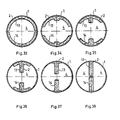
- Figs. 30 to 38 a simpler embodiment with the same theoretical construction as in Figs. 11 to 15 is shown which is easier to manufacture.
- liquid phase 2 is not departed from the inner wall of pipe 1 on the whole diameter, since the channels of this embodiment defined by deflecting surfaces 13 and 14 are not closed in themselves but they are partly limited by the wall of pipe 1 along the whole baffle element 3.
- the outlets of the channels of liquid phase 2 have prismatic shapes, respectively, as shown in Fig. 38.
- the form of channels of phases 2 and 4 and, in this way, the shape of deflecting surfaces 13 and 14 are much simpler than in the previous embodiments which is beneficial to the costs of the production.
- Liquid phase 2 which will not be departed from the wail of pipe 1 with this baffle element 3 can be led away with the next baffle element 3 having the same construction but being arranged in pipe 1 for having the outlets of channels of liquid phase 2 twisted for 90 degrees with respect to the baffle element 3 in front. This causes, that the portions of liquid phase 2 remaining at the wall of pipe 1 behind the first baffle element 3 will be removed from the wall by the next baffle element 3, since these portions will fall right into the middle of the inlets of the channels for liquid phase 2.
- the embodiments shown in Figs. 4 to 10 are suitable for wavy flow pattern and the embodiments in the further figures for ring-shaped flow patterns.
- the baffle elements 3 for the two kinds of flow patterns should alternately be arranged in pipe 1.
- an embodiment of the baffle element 3 can also be provided which is effective for both kinds of flow patterns. For instance, such an embodiment is shown in Figs. 39 to 44.
- This embodiment differs from the previous one shown in figs. 30 to 38 in that the outlet of the channels for liquid phase 2 is twisted for 90 degrees with respect to the outlet of these channels of the previous embodiment. In this way, deflecting surfaces 15 and 16 forming the channels provide a spiral-like path for liquid phase 2. It is apparent, that the boundary layer of liquid phase 2 will be removed from the wall of pipe 1 and, at the same time, liquid phase 2 having a wavy flow pattern will be lifted into the level of the middle line and, simultaneously, it will get a spin, too. This spin of lifted liquid 2 promotes its further motion upwards.
- Figs. 39 to 44 can be twisted even more, e.g. for 180 degrees, too.
- the spin of liquid phase 2 can be increased. It is also possible to use two of the baffle elements shown in these figures tightly one after the other to provide this increased spin of liquid phase 2.
- baffle elements 3 are mostly not longer than three times the diameter of pipe 1. Deflecting surfaces 5 to 10 and 13 to 16 are relatively thin, usually one hundredth of the diameter of pipe 1 but not more than one tenth of it. As mentioned already, the cross sectional surface area of the channels are usually constant throughout the whole length of baffle elements 3, however, channels with narrowing or widening cross sectional area can be advantageous, too. The flow resistance is the lowest in case of channels having constant cross-section.
- a widening channel for liquid portion 2 can be useful for the recooling of viscous liquids, since the gaseous or steam phase 4 having an ever increasing speed will suck liquid phase 2 at the outlet side of the baffle element 3.
- a narrowing channel for liquid portion 2 can be preferred for heating a viscous liquid within the heat exchange pipe 1, since, in this case of use, the boundary layer is hotter, thus, the channels of it should be narrowed.
Abstract
Description
- The invention relates to a heat exchange pipe according to the precharacterizing parts of
claims - It is a well known fact that the heat transfer is quite difficult with agents to be cooled having inhomogeneous composition in cross-sectional direction of the heat exchange pipe. This is the case with agents composed of two different components or having two different phases such as gas and liquid. It is also well known that these agents have in most cases a wavy flow pattern or a ring-shaped flow pattern within the pipe. In the first case, the liquid phase flows in a lower part of the pipe and has a wavy free surface within the pipe, and the gas or vapour streams above this wavy surface. In the latter case, the liquid phase adheres in a ring from to the inner wall of the pipe and encircles the gas or vapour streaming in the middle of the pipe. In both cases, the two phases don't stream together but they occupy two "flow channels" being separated from each other.
- This kind of agents is to be re-cooled on more fields of the industry. In the case of heat pumps or of refrigerators, the agents to be cooled are mixed of two components having different volatilities. These two phases differ not only in their state of aggregation but in their concentrations, too. When the working agent having two phases is cooled, its temperature gets lower and, in the same time, dissolving and condensation occure. Since the two phases stream separately, they are not in a constant thermodynamic equilibrium and, therefore the component being less volatil condensates quicker, the condensate recooles quicker, and the component being more volatile and forming the bigger part of the gaseous phase dissolves later in the liquid phase. Hence, the temperature characteristics of the known heat exchange pipes in dependency of the amount of transferred heat are quite disadvantageous, thus, for a given thermodynamic process, a larger and more expensive heat-exchanger is required for providing the same thermodynamic coefficient.
- The same problems arise when the working agent in the pipe is warmed by a hotter outer agent such as water.
- Since the two components of the working agent get separated, the amount of heat which can be transfered is smaller than what is theoretically attainable.
- In the operation of the known heat exchange pipes, a further disadvantageous effect can also be observed which arises from working agents having only one component.
- In a condenser, for example, the already condensed working agent formes a liquid phase remaining on the inner surface of the pipe wall which hinders the heat transfer between the non-condensed steam phase and the wall of the pipe.
- It has also been found out the above mentioned ring-shaped flow pattern is quite similar to that of the viscous liquids used as working agents in heat exchange pipes. In the first case, the composition of the agent itself having different compositions of different phases is inhomogeneous, and in the latter, the physical conditions (temperature and viscosity) are inhomogeneous to a great extent.
- It is a well know fact that, for example, oils which are used for the lubrication of the bearings of steam-turbines or gas-turbines and cooling thereof and which are cooled in heat exchangers to eliminate the heat arising from the mechanical heat-losses from the bearings, are bad heat conductors and from laminarly in the pipes of the heat-exchangers.
- As a consequence of said properties, the heat transfer coefficient of the oils is low involving the disadvantageous consequence that cooling requires large and expensive heat-exchangers.
- The inferior heat transfer coefficient of laminarly flowing oils with bad heat conductivity can be explained by the fact that the outer layer, having been cooled and flowing with a low velocity along the pipe surface, is acting as thermal insulation and hinders the path of the heat flux from the warmer oil towards the pipewall. While the outer cooled oil is flowing forward with a low velocity on the pipewall, forming a quasi dense layer on the pipewall, the warm oil flows in the middle of the pipe and it is hardly cooled. Heat is able to flow only by way of conductivity.
- According to the practice developed earlier, longitudinally arranged inner ribs are used, which are parallel or substantially parallel to the longitudinal axis of the pipe. Essentially, the heat has to cover a shorter path in the cut-up cross-section, accordingly resistance will be also less. However, the disadvantage of the ribs is that resistance, weight and therefore cost of production of the heat-exchanger are also increased.
- A device for generating special turbulence patterns in fluids flowing in pipes is know from the US-
PS 4 179 222. These devices made of metal sheets are inserted into a pipe and give the flow a component in radial direction additionally to the direction of the axis of the pipe. This causes turbulences and hence an improved heat transfer towards the wall of the pipe. However, the disadvantage of this turbulence generating device is, that there is no defined interchangement of the upper and the lower section of the flow or the middle section and the section near the wall of the pipe. Hence a defined interchangement of the gaseous with the liquid phase of a flow or of a liquid phase of higher viscosity with a liquid phase of lower viscosity is not possible by means of this device. - A heat exchange pipe according to the precharacterizing part of
claim 1 for heat transfer from a medium in the pipe is known from the GB-PS 2 135 439. This heat exchange pipe includes spaced- apart baffle elements disposed within the pipe substantially perpendicularly to the longitudinal axis of the pipe and which have means for deflecting the outer layer of the medium away from the wall of the pipe. - While this solution can be regarded as the most developed one in the state of the art, a few disadvantageous features still deterioritate the efficiency of the heat exchange. The known baffle element has a ring surface being perpendicular to the wall which has to aid the deflecting action. But this ring surface causes a sharp changement of the flow direction which increases the flow resistance within the pipe and, in the same time, it amplifies the tendency of the viscous liquid to by-pass the hindrance, i.e. the ring surface being in its flow path without any substantial change in its laminar flow pattern in the boundary layer.
- Nevertheless, the known baffle element can only be used with said viscous liquids within certain speed and viscosity limits. It is not suitable for wavy flow patterns at all.
- The main object of this invention is to provide a heat exchange pipe according to the precharacterizing part of
claims - This aim is achieved by the features described within the characterizing parts of
claims - The main idea of the invention is that a baffle element should be used within the pipe with which particles of the working agent having eminent importance with respect to the heat transfer coefficient should be transfered to a well defined portion of the pipe when seen in cross section of the pipe. Furthermore, the baffle element should be free of any sharp changes of the flow direction and it should be easy to manufacture and arrange it within the pipe.
- In a preferred embodiment of this invention a surface area of the inlet of the first kind of channels equals that of their outlet.
- It is a preferred embodiment of the invention, wherein the deflecting channels of the baffle elements are free of any sharp directional change and have a constant curvature between the inlets and the outlets of the channels. It can also be preferred that the first portion of the cross-section is limited by the wall and a secant of the cross-section of the pipe and the second portion is limited by the wall and by another secant of the cross-section. Therein the first portion and the second portion are arranged in diametrically opposite positions and the secants are parallel to each other.
- In another preferred embodiment of the invention the first portion of its cross-section is substantially ring-shaped and is partially limited by the wall of the pipe. With this, it is possible that the second portion of its cross-section has a disk-like shape and is arranged in a middle axis of the pipe, or that the second portion of its cross-section is prism-shaped, a middle axis of which coincides with a symmetry line of the cross-section. In the latter case, the second portion can be limited at least partially by the wall of the pipe.
- In a preferred embodiment of this invention more than one baffle element are arranged in the pipe, and the angular dispositions and/or the constructions of the successive baffle elements are different. In all embodiments, the baffle elements can be made of metal plates preferably by pressing. With this, its possible in this invention, that the baffle elements are assembled from at least two metal plates being previously formed by pressing for having identical shapes.
- It can be preferred, that the baffle elements are resiliently pressed against the inner wall of the pipe when arranged therein. The baffle elements can always be attached to a fixing wire which is fixed to the pipe.
- For the baffle element is preferable, when a length of the baffle element measured in direction of the longitudinal axis of the pipe is maximally three- times larger than the diameter of the pipe. According to a further preferred embodiment a thickness of the metal plate material of the baffle elements is maximally one tenth of the diameter of the pipe. Finally, it is preferably if the flow channels within the baffle element have a helical design. Further objects and details of this invention will be described hereinafter with reference to the accompanying drawing on the basis of preferred embodiments. In the drawing
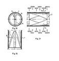
- Fig. 1 shows a first embodiment of the heat exchange pipe in this invention in cross-section,
- Fig. 2 and
- Fig. 3 illustrate side elevational views of the embodiment in Fig. 1 from two different directions when the pipe is cut away,
- Fig. 4 to
- Fig. 10 show the same sequence of cross-sections as indicated by lines IV to X in Fig. 2,
- Fig. 11 to
- Fig. 15 show the same sequence of cross-sections as in Figs. 11 to 15 but for another preferred embodiment of this invention,
- Fig. 16 to
- Fig. 20 show the same illustration as in Figs. 11 to 15 but for still another embodiment of this invention,
- Fig. 21 shows another embodiment of the heat exchange pipe in this invention in cross-section,
- Fig. 22 and
- Fig. 23 show side elevational views of the embodiment in Fig. 21 from two different directions when the pipe is cut away,
- Fig. 24 to
- Fig. 29 illustrate a sequence of cross-sections as indicated by lines XXIV to XXIX in Fig. 22,
- Fig. 30 shows still another embodiment of this invention in cross-section,
- Fig. 31 and
- Fig. 32 illustrate side elevational views of the embodiment in Fig. 30 from two different directions when the pipe is cut away,
- Fig. 33 to
- Fig. 38 show a sequence of cross sections as indicated by lines XXXIII to XXXVIII in Fig. 31, finally
- Fig. 39 to
- Fig. 44 show a similar sequence of cross-sections as in Figs. 33 to 38 but for another embodiment of this invention.
- Referring now to the drawings in more detail, Figures 1 to 10 illustrate a first preferred embodiment of the
heat exchange pipe 1 according to this invention. For instance this embodiment can preferably be used for working agents which or the liquid phase of which forms a wavy flow pattern. - This liquid phase is referred to by
reference numeral 2 throughout the whole description. Inpipe 1, abaffle element 3 is arranged, which is shown in Figs. 4 to 10 always by a line showing the deflecting surface which is cut by the cutting plane generating the cross-sections. With thisbaffle element 3,liquid phase 2 is lifted from a lower part of the cross-section ofpipe 1 in fig. 4 to a higher part of it in Fig. 10.Baffle element 3 as shown in Fig. 4 is formed for exactly separatingliquid phase 2 from a gaseous orsteam phase 4 of the working agent streaming inpipe 1. In this way,liquid phase 2 and gaseous orsteam phase 4 as shown in Fig. 4 correspond to an inlet of two separated channels ofbaffle element 3. In the lower one defined by the wall ofpipe 1 and the deflecting surface ofbaffle element 3,liquid phase 2 and in the upper one defined by the other side of the deflecting surface ofbaffle element 3 and the remaining part of the wall ofpipe 1 the gaseous orsteam phase 4 are forwarded. With this, a first kind of channel forliquid phase 2 and a second kind of channel for gaseous orsteam phase 4 are provided inbaffle element 3. - The form of the channels in the respective cross-sections according to lines IV to X in Fig. 2 can be seen in Figs. 4 to 10. It is apparent that the deflecting surfaces determining the channels have streamlined shapes, thus, the phases won't suffer from any sharp change in direction of their flow. Throughout the whole path within the
baffle element 3, each ofphases liquid phase 2 in a higher portion of the cross-section in the height of which the inlet of the channel of gaseous or steam phase 4 (Fig. 15) is, and that of gaseous orsteam portion 4 in a lower portion of the cross-section, in the height of which the inlet of the channel for liquid phase 2 (Fig. 15) is. In this way, theliquid phase 2 is in its whole amount separated from the wall ofpipe 1 and it changes place with gaseous orsteam phase 4. At the outlet,liquid phase 2 is again contacted with the inner wall of pipe 1 (see Figs. 8 to 10). - In the above described embodiment,
heat exchange pipe 1 has a circular cross-section, wherein the deflecting surfaces at the inlet and the outlet of the channels are formed as secants of the circle which are parallel to each other. The surface areas determined by the secants and the inner wall of thepipe 1 for the channel ofliquid phase 2 are equal at the inlet and at the outlet, respectively. In another embodiment, the surface area of the outlet of the channel of theliquid phase 2 can be larger than the inlet and, with this, a continuously narrowing channel can be provided for gaseous orsteam phase 4. Thus, the speed of thisphase 4 will be enlargened andliquid phase 2 will be sucked on the outlet side ofbaffle element 3. This arrangement is very useful in applications wherein theliquid phase 2 has a relatively low streaming speed and the energy for its "lifting" must additionally be provided. Nevertheless, the latter embodiment raises the flow resistance, however, it could be necessary. - In Figs. 11 to 15, the same sequence of cross-sections is shown as of the previous embodiment, however, this embodiment can be used for the ring-shaped flow pattern, in the case of which
liquid phase 2 is adhered to the wall ofpipe 1 in a ring form. This embodiment differs from the previous one in that, too, that the channels are formed of two deflectingsurfaces pipe 1 forliquid phase 2. The inlet of the channel forphase 4 is in the centre ofpipe 1, the deflecting channel is defined by deflectingsurfaces liquid phase 2. In Figs. 16 to 20 another embodiment is shown for the same application. Therein, three deflectingsurfaces liquid phase 2 having a common ring-shaped inlet and a common outlet in the centre ofpipe 1. - Whilst in the previous figures theoretical realization possibilities of the
heat exchange pipe 1 of this invention were shown, Figs. 21 to 29 illustrate an embodiment which is easy to manufacture. This embodiment corresponds to that shown in figs. 11 to 15 whereinbaffle element 3 has two deflectingsurfaces surfaces liquid phase 2 between the ring-shaped inlet and the outlet in the centre ofpipe 1.Edges 11 and 12 of deflectingsurfaces pipe 1 in the whole length ofbaffle element 3. In contrast to the drawing, edges 11, 12 are contacted in tight relationship, so thatliquid phase 2 having the ring-shaped flow pattern can only enter its channels between the wall ofpipe 1 and deflectingsurfaces surfaces pipe 1 as shown in Fig. 29. At the outlet, edges 11 of deflectingsurface 6 and edges 12 of deflectingsurface 7 are tightly connected to each other, respectively. In this way, the boundary layer ofliquid phase 2 will totally be separated from the wall ofpipe 1 and led through the channels into the centre ofpipe 1. At the same time, gaseous orsteam phase 4 streaming in the middle ofpipe 1 enters its channel in Fig. 24 and leaves it at the outlet in ring form around deflectingsurfaces phases baffle element 3. - Since
edges 11 and 12 contact the wall ofpipe 1 in the whole length,baffle element 3 can be fixed within thepipe 1 with the aid of the resilient force of deflectingsurfaces baffle element 3 has to be made for having a bigger diameter than the actual diameter ofpipe 1 and it will slightly be compressed when arranging it within the pipe. The resilient force of the metal sheet material ofbaffle element 3 will fix it in thepipe 1. - However, a fixing wire can also be used for fixing the axial position of
baffle elements 3 inpipe 1. This fixing wire (not shown in the drawing) can be attached to deflectingsurfaces edges 11 and 12. - In Fig. 22, stream lines of
phases baffle element 3 can be operated with opposite flow direction R2, too, only the cross sectional ratios have to be determined according to the actual flow direction. - In Figs. 30 to 38, a simpler embodiment with the same theoretical construction as in Figs. 11 to 15 is shown which is easier to manufacture. However,
liquid phase 2 is not departed from the inner wall ofpipe 1 on the whole diameter, since the channels of this embodiment defined by deflectingsurfaces pipe 1 along thewhole baffle element 3. Thus, the outlets of the channels ofliquid phase 2 have prismatic shapes, respectively, as shown in Fig. 38. The form of channels ofphases surfaces Liquid phase 2 which will not be departed from the wail ofpipe 1 with thisbaffle element 3 can be led away with thenext baffle element 3 having the same construction but being arranged inpipe 1 for having the outlets of channels ofliquid phase 2 twisted for 90 degrees with respect to thebaffle element 3 in front. This causes, that the portions ofliquid phase 2 remaining at the wall ofpipe 1 behind thefirst baffle element 3 will be removed from the wall by thenext baffle element 3, since these portions will fall right into the middle of the inlets of the channels forliquid phase 2. - As it is mentioned above, the embodiments shown in Figs. 4 to 10 are suitable for wavy flow pattern and the embodiments in the further figures for ring-shaped flow patterns. However, it often occurs that, because of the changing operational conditions, the flow pattern is sometimes wavy, sometimes a ring-shaped one. Therefore, the
baffle elements 3 for the two kinds of flow patterns should alternately be arranged inpipe 1. However, an embodiment of thebaffle element 3 can also be provided which is effective for both kinds of flow patterns. For instance, such an embodiment is shown in Figs. 39 to 44. - This embodiment differs from the previous one shown in figs. 30 to 38 in that the outlet of the channels for
liquid phase 2 is twisted for 90 degrees with respect to the outlet of these channels of the previous embodiment. In this way, deflectingsurfaces liquid phase 2. It is apparent, that the boundary layer ofliquid phase 2 will be removed from the wall ofpipe 1 and, at the same time,liquid phase 2 having a wavy flow pattern will be lifted into the level of the middle line and, simultaneously, it will get a spin, too. This spin of lifted liquid 2 promotes its further motion upwards. - Nevertheless, the embodiment shown in Figs. 39 to 44 can be twisted even more, e.g. for 180 degrees, too. By means of this, the spin of
liquid phase 2 can be increased. It is also possible to use two of the baffle elements shown in these figures tightly one after the other to provide this increased spin ofliquid phase 2. - As shown in the drawings,
baffle elements 3 are mostly not longer than three times the diameter ofpipe 1. Deflecting surfaces 5 to 10 and 13 to 16 are relatively thin, usually one hundredth of the diameter ofpipe 1 but not more than one tenth of it. As mentioned already, the cross sectional surface area of the channels are usually constant throughout the whole length ofbaffle elements 3, however, channels with narrowing or widening cross sectional area can be advantageous, too. The flow resistance is the lowest in case of channels having constant cross-section. - A widening channel for
liquid portion 2 can be useful for the recooling of viscous liquids, since the gaseous orsteam phase 4 having an ever increasing speed will suckliquid phase 2 at the outlet side of thebaffle element 3. In contrast to this, a narrowing channel forliquid portion 2 can be preferred for heating a viscous liquid within theheat exchange pipe 1, since, in this case of use, the boundary layer is hotter, thus, the channels of it should be narrowed.
Claims (11)
Priority Applications (1)
| Application Number | Priority Date | Filing Date | Title |
|---|---|---|---|
| AT87105810T ATE48697T1 (en) | 1986-04-21 | 1987-04-21 | HEAT EXCHANGE TUBE FOR HEAT TRANSFER. |
Applications Claiming Priority (2)
| Application Number | Priority Date | Filing Date | Title |
|---|---|---|---|
| HU164886 | 1986-04-21 | ||
| HU861648A HU199979B (en) | 1986-04-21 | 1986-04-21 | Method and heat-exchanger insert for improving the heat transfer of media flowing in the tubes of heat exchanger and having inhomogeneous composition and/or inhomogeneous physical state |
Publications (2)
| Publication Number | Publication Date |
|---|---|
| EP0242838A1 EP0242838A1 (en) | 1987-10-28 |
| EP0242838B1 true EP0242838B1 (en) | 1989-12-13 |
Family
ID=10955505
Family Applications (1)
| Application Number | Title | Priority Date | Filing Date |
|---|---|---|---|
| EP87105810A Expired EP0242838B1 (en) | 1986-04-21 | 1987-04-21 | A heat exchange pipe for heat transfer |
Country Status (8)
| Country | Link |
|---|---|
| US (1) | US4881596A (en) |
| EP (1) | EP0242838B1 (en) |
| JP (1) | JPS6317394A (en) |
| AT (1) | ATE48697T1 (en) |
| DE (1) | DE3761169D1 (en) |
| ES (1) | ES2012069B3 (en) |
| GR (1) | GR3000253T3 (en) |
| HU (1) | HU199979B (en) |
Cited By (1)
| Publication number | Priority date | Publication date | Assignee | Title |
|---|---|---|---|---|
| AT402672B (en) * | 1993-06-14 | 1997-07-25 | Vaillant Gmbh | DISPLACEMENT |
Families Citing this family (20)
| Publication number | Priority date | Publication date | Assignee | Title |
|---|---|---|---|---|
| US5161959A (en) * | 1991-03-11 | 1992-11-10 | Ford Motor Company | Viscosity sensitive hydraulic pump flow control |
| AT402347B (en) * | 1993-03-11 | 1997-04-25 | Vaillant Gmbh | HEAT EXCHANGER PIPE |
| US5388398A (en) * | 1993-06-07 | 1995-02-14 | Avco Corporation | Recuperator for gas turbine engine |
| ATE216062T1 (en) * | 1995-06-20 | 2002-04-15 | Andritz Ahlstrom Oy | METHOD AND DEVICE FOR TREATING A POOR HEAT-CONDUCTING MATERIAL |
| US5785808A (en) * | 1995-10-02 | 1998-07-28 | Lci Corporation | Heat exchanger with pressure controlling restricter |
| FI111963B (en) * | 1998-01-30 | 2003-10-15 | Andritz Oy | Method and apparatus for treating low heat conductive material |
| DE59812898D1 (en) * | 1998-09-24 | 2005-08-04 | Alstom Technology Ltd Baden | Flow channel for the passage of a two-phase flow |
| DE19938840A1 (en) * | 1999-08-17 | 2001-03-15 | Emitec Emissionstechnologie | Mixing element for a fluid guided in a pipe |
| US6729386B1 (en) * | 2001-01-22 | 2004-05-04 | Stanley H. Sather | Pulp drier coil with improved header |
| US6615872B2 (en) | 2001-07-03 | 2003-09-09 | General Motors Corporation | Flow translocator |
| US6732788B2 (en) * | 2002-08-08 | 2004-05-11 | The United States Of America As Represented By The Secretary Of The Navy | Vorticity generator for improving heat exchanger efficiency |
| DE102006016559A1 (en) * | 2006-04-07 | 2007-10-11 | Air Liquide Deutschland Gmbh | Heat exchanger for a mobile refrigerated vehicle |
| US20090087604A1 (en) * | 2007-09-27 | 2009-04-02 | Graeme Stewart | Extruded tube for use in heat exchanger |
| DE102008030423B4 (en) | 2007-12-05 | 2016-03-03 | GIB - Gesellschaft für Innovation im Bauwesen mbH | Pipe with a surface profile-modified outer surface by pimples |
| US8613308B2 (en) | 2010-12-10 | 2013-12-24 | Uop Llc | Process for transferring heat or modifying a tube in a heat exchanger |
| US9605913B2 (en) * | 2011-05-25 | 2017-03-28 | Saudi Arabian Oil Company | Turbulence-inducing devices for tubular heat exchangers |
| US20160177806A1 (en) * | 2014-12-23 | 2016-06-23 | Caterpillar Inc. | Exhaust Outlet Elbow Center Divider Connection |
| EP3040638B1 (en) * | 2015-07-23 | 2018-05-09 | Hoval Aktiengesellschaft | Heat transfer pipe and boiler comprising one such heat transfer pipe |
| US9982915B2 (en) | 2016-02-23 | 2018-05-29 | Gilles Savard | Air heating unit using solar energy |
| CA2964399A1 (en) * | 2016-04-12 | 2017-10-12 | Ecodrain Inc. | Heat exchange conduit and heat exchanger |
Family Cites Families (12)
| Publication number | Priority date | Publication date | Assignee | Title |
|---|---|---|---|---|
| US2335687A (en) * | 1941-08-25 | 1943-11-30 | Arthur B Modine | Radiator core |
| US2929408A (en) * | 1955-04-27 | 1960-03-22 | Acme Ind Inc | Fin construction |
| DE1401669A1 (en) * | 1962-10-04 | 1968-10-17 | Linde Ag | Method and device for heat exchange between two media on a heat exchanger tube |
| US3470912A (en) * | 1966-11-30 | 1969-10-07 | Du Pont | Flow inverter |
| GB1389508A (en) * | 1973-09-17 | 1975-04-03 | Apv Co Ltd | Turbulence promoting devices |
| CA982549A (en) * | 1973-10-29 | 1976-01-27 | Richard E. Harder | Annular spiral interfacial surface generator |
| US4179222A (en) * | 1978-01-11 | 1979-12-18 | Systematix Controls, Inc. | Flow turbulence generating and mixing device |
| US4407269A (en) * | 1978-07-07 | 1983-10-04 | Sunsearch, Inc. | Solar energy collector system having balanced heat-exchange fluid flow |
| US4208136A (en) * | 1978-12-01 | 1980-06-17 | Komax Systems, Inc. | Static mixing apparatus |
| DE3226420C2 (en) * | 1982-07-15 | 1986-06-05 | CEM Ingenieurgesellschaft mbH, 6000 Frankfurt | Static mixing device for mixing gases, liquids and solids in single or multi-phase systems |
| HU187016B (en) * | 1983-02-01 | 1985-10-28 | Energiagazdalkodasi Intezet | Device for improving the heat-transfer coefficient of viscous liquids flowing in the tubes of heat exchangers |
| US4577681A (en) * | 1984-10-18 | 1986-03-25 | A. O. Smith Corporation | Heat exchanger having a turbulator construction |
-
1986
- 1986-04-21 HU HU861648A patent/HU199979B/en not_active IP Right Cessation
-
1987
- 1987-04-21 AT AT87105810T patent/ATE48697T1/en not_active IP Right Cessation
- 1987-04-21 EP EP87105810A patent/EP0242838B1/en not_active Expired
- 1987-04-21 JP JP62096343A patent/JPS6317394A/en active Pending
- 1987-04-21 ES ES87105810T patent/ES2012069B3/en not_active Expired - Lifetime
- 1987-04-21 DE DE8787105810T patent/DE3761169D1/en not_active Expired - Fee Related
-
1989
- 1989-04-17 US US07/339,893 patent/US4881596A/en not_active Expired - Fee Related
- 1989-12-14 GR GR89400258T patent/GR3000253T3/en unknown
Cited By (1)
| Publication number | Priority date | Publication date | Assignee | Title |
|---|---|---|---|---|
| AT402672B (en) * | 1993-06-14 | 1997-07-25 | Vaillant Gmbh | DISPLACEMENT |
Also Published As
| Publication number | Publication date |
|---|---|
| US4881596A (en) | 1989-11-21 |
| ATE48697T1 (en) | 1989-12-15 |
| DE3761169D1 (en) | 1990-01-18 |
| HU199979B (en) | 1990-03-28 |
| HUT49942A (en) | 1989-11-28 |
| EP0242838A1 (en) | 1987-10-28 |
| ES2012069B3 (en) | 1990-03-01 |
| JPS6317394A (en) | 1988-01-25 |
| GR3000253T3 (en) | 1991-03-15 |
Similar Documents
| Publication | Publication Date | Title |
|---|---|---|
| EP0242838B1 (en) | A heat exchange pipe for heat transfer | |
| US4211277A (en) | Heat exchanger having internal fittings | |
| Wang et al. | Heat transfer and friction correlation for compact louvered fin-and-tube heat exchangers | |
| US3840070A (en) | Evaporator-condenser | |
| Hong et al. | Performance of dehumidifying heat exchangers with and without wetting coatings | |
| US4641705A (en) | Modification for heat exchangers incorporating a helically shaped blade and pin shaped support member | |
| EP1971815B1 (en) | Spirally wound, layered tube heat exchanger | |
| CN101490494A (en) | Spiral flat-tube heat exchanger | |
| KR870011443A (en) | Heat exchanger | |
| CN109742062A (en) | Bionical point of shape plate heat exchanger | |
| JPH06185885A (en) | Flat multi-holed condensing and heat transfer pipe | |
| JPH07253287A (en) | Heat exchanger tube having internal element | |
| GB2065281A (en) | Controlled performance heat exchanger for evaporative and condensing processes | |
| US1961907A (en) | Apparatus for heat exchanging | |
| JP3256634B2 (en) | Heat exchanger | |
| SE519306C2 (en) | Heat transfer plate, plate package and plate heat exchanger | |
| Shah | Extended surface heat transfer | |
| US4402362A (en) | Plate heat exchanger | |
| US4564066A (en) | Perforate bearing plate for turbulators in heat exchangers | |
| RU2027137C1 (en) | Heat exchanger | |
| GB2135439A (en) | Heat exchange pipes | |
| GB2037974A (en) | Heat transfer tube | |
| US5159975A (en) | Unit to enhance heat transfer through heat exchanger tube | |
| RU2066036C1 (en) | Heat exchange member | |
| JP2019184133A (en) | Heat exchanger |
Legal Events
| Date | Code | Title | Description |
|---|---|---|---|
| PUAI | Public reference made under article 153(3) epc to a published international application that has entered the european phase |
Free format text: ORIGINAL CODE: 0009012 |
|
| AK | Designated contracting states |
Kind code of ref document: A1 Designated state(s): AT BE CH DE ES FR GB GR IT LI LU NL SE |
|
| 17P | Request for examination filed |
Effective date: 19880427 |
|
| 17Q | First examination report despatched |
Effective date: 19880816 |
|
| GRAA | (expected) grant |
Free format text: ORIGINAL CODE: 0009210 |
|
| AK | Designated contracting states |
Kind code of ref document: B1 Designated state(s): AT BE CH DE ES FR GB GR IT LI LU NL SE |
|
| REF | Corresponds to: |
Ref document number: 48697 Country of ref document: AT Date of ref document: 19891215 Kind code of ref document: T |
|
| ITF | It: translation for a ep patent filed |
Owner name: ING. C. GREGORJ S.P.A. |
|
| REF | Corresponds to: |
Ref document number: 3761169 Country of ref document: DE Date of ref document: 19900118 |
|
| ET | Fr: translation filed | ||
| REG | Reference to a national code |
Ref country code: GR Ref legal event code: FG4A Free format text: 3000253 |
|
| PLBI | Opposition filed |
Free format text: ORIGINAL CODE: 0009260 |
|
| 26 | Opposition filed |
Opponent name: JOH. VAILLANT GMBH U. CO Effective date: 19900816 |
|
| NLR1 | Nl: opposition has been filed with the epo |
Opponent name: JOH. VAILLANT GMBH U. CO. |
|
| ITTA | It: last paid annual fee | ||
| PGFP | Annual fee paid to national office [announced via postgrant information from national office to epo] |
Ref country code: GR Payment date: 19920522 Year of fee payment: 6 |
|
| PGFP | Annual fee paid to national office [announced via postgrant information from national office to epo] |
Ref country code: ES Payment date: 19920525 Year of fee payment: 6 |
|
| PGFP | Annual fee paid to national office [announced via postgrant information from national office to epo] |
Ref country code: LU Payment date: 19920526 Year of fee payment: 6 |
|
| EPTA | Lu: last paid annual fee | ||
| PG25 | Lapsed in a contracting state [announced via postgrant information from national office to epo] |
Ref country code: LU Free format text: LAPSE BECAUSE OF NON-PAYMENT OF DUE FEES Effective date: 19930421 |
|
| PG25 | Lapsed in a contracting state [announced via postgrant information from national office to epo] |
Ref country code: ES Free format text: LAPSE BECAUSE OF NON-PAYMENT OF DUE FEES Effective date: 19930422 |
|
| PG25 | Lapsed in a contracting state [announced via postgrant information from national office to epo] |
Ref country code: GR Free format text: THE PATENT HAS BEEN ANNULLED BY A DECISION OF A NATIONAL AUTHORITY Effective date: 19931031 |
|
| PLBN | Opposition rejected |
Free format text: ORIGINAL CODE: 0009273 |
|
| STAA | Information on the status of an ep patent application or granted ep patent |
Free format text: STATUS: OPPOSITION REJECTED |
|
| 27O | Opposition rejected |
Effective date: 19940715 |
|
| NLR2 | Nl: decision of opposition | ||
| REG | Reference to a national code |
Ref country code: GR Ref legal event code: MM2A Free format text: 3000253 |
|
| EAL | Se: european patent in force in sweden |
Ref document number: 87105810.3 |
|
| PGFP | Annual fee paid to national office [announced via postgrant information from national office to epo] |
Ref country code: SE Payment date: 19950330 Year of fee payment: 9 Ref country code: CH Payment date: 19950330 Year of fee payment: 9 |
|
| PGFP | Annual fee paid to national office [announced via postgrant information from national office to epo] |
Ref country code: FR Payment date: 19950331 Year of fee payment: 9 Ref country code: BE Payment date: 19950331 Year of fee payment: 9 |
|
| PGFP | Annual fee paid to national office [announced via postgrant information from national office to epo] |
Ref country code: GB Payment date: 19950410 Year of fee payment: 9 |
|
| PGFP | Annual fee paid to national office [announced via postgrant information from national office to epo] |
Ref country code: NL Payment date: 19950430 Year of fee payment: 9 Ref country code: AT Payment date: 19950430 Year of fee payment: 9 |
|
| PGFP | Annual fee paid to national office [announced via postgrant information from national office to epo] |
Ref country code: DE Payment date: 19950630 Year of fee payment: 9 |
|
| PG25 | Lapsed in a contracting state [announced via postgrant information from national office to epo] |
Ref country code: GB Effective date: 19960421 Ref country code: AT Effective date: 19960421 |
|
| PG25 | Lapsed in a contracting state [announced via postgrant information from national office to epo] |
Ref country code: SE Effective date: 19960422 |
|
| PG25 | Lapsed in a contracting state [announced via postgrant information from national office to epo] |
Ref country code: LI Effective date: 19960430 Ref country code: CH Effective date: 19960430 Ref country code: BE Effective date: 19960430 |
|
| BERE | Be: lapsed |
Owner name: ENERGIAGAZDALKODASI INTEZET Effective date: 19960430 |
|
| PG25 | Lapsed in a contracting state [announced via postgrant information from national office to epo] |
Ref country code: NL Effective date: 19961101 |
|
| GBPC | Gb: european patent ceased through non-payment of renewal fee |
Effective date: 19960421 |
|
| REG | Reference to a national code |
Ref country code: CH Ref legal event code: PL |
|
| PG25 | Lapsed in a contracting state [announced via postgrant information from national office to epo] |
Ref country code: FR Effective date: 19961227 |
|
| PG25 | Lapsed in a contracting state [announced via postgrant information from national office to epo] |
Ref country code: DE Effective date: 19970101 |
|
| NLV4 | Nl: lapsed or anulled due to non-payment of the annual fee |
Effective date: 19961101 |
|
| EUG | Se: european patent has lapsed |
Ref document number: 87105810.3 |
|
| REG | Reference to a national code |
Ref country code: FR Ref legal event code: ST |
|
| REG | Reference to a national code |
Ref country code: ES Ref legal event code: FD2A Effective date: 19990201 |
|
| PG25 | Lapsed in a contracting state [announced via postgrant information from national office to epo] |
Ref country code: IT Free format text: LAPSE BECAUSE OF NON-PAYMENT OF DUE FEES Effective date: 20050421 |
|
| APAH | Appeal reference modified |
Free format text: ORIGINAL CODE: EPIDOSCREFNO |