EP0242825A2 - Apparatus for interchanging orifice plates for orifice flowmeter - Google Patents
Apparatus for interchanging orifice plates for orifice flowmeter Download PDFInfo
- Publication number
- EP0242825A2 EP0242825A2 EP87105738A EP87105738A EP0242825A2 EP 0242825 A2 EP0242825 A2 EP 0242825A2 EP 87105738 A EP87105738 A EP 87105738A EP 87105738 A EP87105738 A EP 87105738A EP 0242825 A2 EP0242825 A2 EP 0242825A2
- Authority
- EP
- European Patent Office
- Prior art keywords
- plate
- orifice plate
- orifice
- mount portion
- pin
- Prior art date
- Legal status (The legal status is an assumption and is not a legal conclusion. Google has not performed a legal analysis and makes no representation as to the accuracy of the status listed.)
- Granted
Links
Images


Classifications
-
- G—PHYSICS
- G01—MEASURING; TESTING
- G01F—MEASURING VOLUME, VOLUME FLOW, MASS FLOW OR LIQUID LEVEL; METERING BY VOLUME
- G01F1/00—Measuring the volume flow or mass flow of fluid or fluent solid material wherein the fluid passes through a meter in a continuous flow
- G01F1/05—Measuring the volume flow or mass flow of fluid or fluent solid material wherein the fluid passes through a meter in a continuous flow by using mechanical effects
- G01F1/34—Measuring the volume flow or mass flow of fluid or fluent solid material wherein the fluid passes through a meter in a continuous flow by using mechanical effects by measuring pressure or differential pressure
- G01F1/36—Measuring the volume flow or mass flow of fluid or fluent solid material wherein the fluid passes through a meter in a continuous flow by using mechanical effects by measuring pressure or differential pressure the pressure or differential pressure being created by the use of flow constriction
- G01F1/40—Details of construction of the flow constriction devices
- G01F1/42—Orifices or nozzles
Definitions
- the present invention relates to an apparatus for interchanging orifice plates for an orifice flowmeter.
- orifice plate refers to a plate having a flow restricting aperture, i.e., an orifice.
- orifice flowmeters comprise an orifice plate disposed at an intermediate portion of a pipe channel.
- Standards are set for such orifice plates as to the shape and dimensions of the orifice, and standardized orifice plates are usable for measuring flow rates without the necessity of calibration.
- a single orifice plate is designed for measuring a specified range of flow rates, such that a change of flow rate range requires use of a different orifice plate.
- orifice plates are changed usually by disassembling the fluid pipe, the procedure is cumbersome and takes much time.
- experiments are sometimes conducted at frequently altered flow rates laboratories or the like, changing orifice plates requires a long period of time and is very inefficient. Further when a toxic fluid is passed through the pipe channel, orifice plate changing involves a hazard, must be done with care and therefore requires a very long period of time.
- the main object of the present invention is to provide an apparatus for interchanging orifice plates with ease and safety without disassembling the fluid pipe of the orifice flowmeter.
- the present invention provides an apparatus for interchanging orifice plates for a orifice flowmeter, characterized in that the apparatus comprises a closed orifice plate stowage disposed outside an orifice plate mount portion at an intermediale portion of a pipe channel and having a communication opening on one side of the mount portion for passing the orifice plate therethrough, the plate stowage being in communication with the mount portion through the opening, a movable body housed in the plate stowage and movable in a direction parallel with the pipe channel, the movable body having a plurality of orifice plate bins arranged in parallel with the pipe channel at a spacing, and a device for moving the orifice plates one by one between the mount portion and the plate bins of the movable body through the communication opening.
- orifice plates can be changed with ease and safety without disassembling the fluid pipe of the orifice flowmeter. Accordingly, when orifice plates are frequently changed in laboratories or the like or even if a toxic fluid is passed through the pipe channel, the orifice plates can be changed within a greatly shortened period of time, hence a high efficiency. Further since the apparatus is adapted to interchange a plurality of orifice plates, standardized orifice plates are usable which need no calibration. The apparatus is therefore highly useful.
- Fig. l shows a horizontal pipe channel l0 of an orifice flowmeter and an orifice plate interchanging apparatus ll mounted on the channel.
- the channel l0 is provided by pipes l2, l3 and pipe flanges l4, l5, l6 and l7.
- a fluid is passed from the left side rightward in the drawing.
- the terms "front,” “rear,” “right” and “left” are hereinafter used with respect to the direction of flow of the fluid. More specifically stated with reference to Fig. l, the right side of the drawing is front, the left side is rear, the rear side of the plane of the drawing is left and the front side thereof is right.
- a rectangular parallelepipedal first block l8 for installing an orifice plate 39 therein is held between the two flanges l5, l6.
- a closed orifice plate stowage 20 positioned in parallel with the channel l0 is fixedly mounted on a flange l9 at the upper end of the block l8.
- the plate stowage 20 comprises a rectangular parallelepipedal main body 2l having an open rear end and a closure 22 for closing the open end.
- the main body 2l is internally provided at its four corners with upper and lower opposed four guides 23 extending along the channel l0 and has upper and lower two stoppers 24 at the front end of the body 2l inside thereof.
- a lower guide rail 26 extending longitudinally of the channel l0 is secured to each of the right and left sides of the frame 25 at its bottom.
- An upper guide rail 27 projecting horizontally inward is integral with each of right and left sides of the frame 25 at its top.
- the upper guide rail 27 is fixedly provided with a plurality of shoes 28 on its upper side.
- the frame 25 is inserted into the main body 2l along the upper wall lower surface, the bottom wall upper surface and the guides 23 and is positioned in place by these walls, the guides and the stoppers 24. With the frame 25 thus positioned in place, the closure 22 is fixed to the stowage main body 2l to close the body.
- a movable rack (body) 29 in the form of a rectangular parallelepipedal frame is provided between the guide rails 26, 27 of the frame 25 and is slidable toward the front and rear.
- the movable rack 29 has a pair of upper opposite shoes 82 and a pair of lower opposite shoes 83 extending longitudinally of the channel l0.
- a motor 3l for driving the movable rack 29 is fixedly provided within a closed case 30 in front of the closure 22 and has a shaft 3la fixedly carrying a pulley 32.
- a rope 33 reeved around the pulley 32 has one end attached to the rear end of the movable rack 29, is passed around a pulley 34 disposed at a rear portion of the frame 25 on the left side thereof and around two pulleys 35, 36 arranged at the front end of the frame 25 and is connected at other end to the front end of the rack 29.
- the movable rack 29 has a plurality of (e.g. five) orifice plate bins 38 separated by partition members 37 and arranged longitudinally of the rack (the channel) at a given spacing. Orifice plates 39 are stowed in the bins 38 respectively.
- Guide members 40, 4l are fixedly provided at the left and right sides of each bin 38, respectively.
- the opposed guide faces 40a and 4la of the left and right guide members 40, 4l are on the same vertical plane as the opposed guide faces 83a of the lower shoes 83 and the opposed guide faces 26a of the lower guide rails 26 at the left and right sides of the stowage 20, respectively. At each of these sides, the guide faces provide a vertically continous face.
- the left guide member 40 is formed at its upper end an outwardly recessed portion 42 for locking the orifice plate.
- the bottom face 42a of the recessed portion 42 is continuous with a slanting face 42b, which in turn is continuous with the guide face 40a
- the orifice plate 39 is generally rectangular parallelepipedal and has an orifice 43 in its center.
- the front-to-rear thickness of the orifice plate 39 is slightly smaller than the spacing between the partition members 38.
- the right-to-left width of the plate is slightly smaller than the distance between the guide members 40, 4l.
- the height of the plate is smaller than the height of the bin 38.
- An engaging cavity 44 is formed in the center of the upper end face of the orifice plate 39, with a coiled spring 45 attached to the bottom of the cavity 44.
- the orifice plate 39 is formed, in an upper portion of its left end face, with a stepped bore 46 extending into the cavity 44.
- a stepped pin 47 slightly longer than the bore 46 is inserted in the bore from the left side.
- a coiled spring 48 for biasing the pin 47 leftward is provided between the stepped portion of the bore 46 and the stepped portion of the pin 47.
- the upper wall 2la of the stowage main body 2l has a guide bore 49 extending vertically therethrough approximately in its center.
- a cup-shaped closure 50 is fixed to the upper side of the upper wall 2la for closing the bore 49.
- a device 5l for moving the orifice plate is provide at this portion.
- the device 5l comprises a lift rod (handling rod) 52 extending downward through the guide bore 49 and an air cylinder 84 for lifting and lowering the rod 52.
- the air cylinder 84 is fixed to the top of the closure 50 as oriented vertically downward and has an unillustrated piston connected to the lift rod 52.
- the rod 52 extends downward through a hole 85 in the top wall of the closure 50, with a packing 86 fitted in the hole 85 around the rod 52.
- a trapezoidal pushing plate 53 is secured to the lower end of the lift rod 52 on an outer side portion thereof.
- a pin 54 smaller than the rod 52 in diameter integrally extends from the center of the lower end face of the rod 52.
- An engaging flange 55 is integral with the lower end of the pin 54.
- the flange 55 has an outside diameter smaller than the diameter of the upper end cavity 44 of the orifice plate 39.
- the plate moving device 5l has suitable means for rotating the rod 52 through 90 degrees about its axis at a specified position as will be described later.
- the bottom wall 2lb of the stowage main body 2l is formed with a rectangular communication opening 56 for the orifice plate 39 to pass therethrough.
- the opening 56 is defined by right and left opposed guide faces 56a and front and rear opposed guide faces 56b.
- the guide face 56a is flush and continuous with the guide face 26a of the lower guide rail 26 on the bottom wall 2lb.
- the guide face 56b is flush with the guide face 37a of the partition member 37 at each of front and rear sides of the opening 56.
- the motor 3l moves the movable rack 29 forward or rearward by one bin pitch or several bin pitches so as to position the desired bin 38 between the opening 56 and the lift rod 52 in its raised position.
- the adjustment of such movement of the movable rack 29 and the replacement of orifice plates 39 can be made easily with the closure 22 removed from the stowage main body 2l.
- the first block l8 has a cavity 57 extending to its bottom and having a rectangular horizontal section.
- a second block 58 for installing the orifice plate therein is fitted in the cavity 57.
- the first block l8 has a front wall l8a defining the cavity 57 and formed with a circular hole 59 concentric with the flange l5 fixed to the wall.
- the flange l5 has a rear portion fitted in the circular hole 59 and a rear end face flush with the rear surface (guide face) l8b of the front wall l8a.
- An O-ring 60 is attached to the flange end face.
- the first block l8 has a rear wall l8c defining the cavity 57 and formed with a circular hole 6l concentric with the flange l6 fixed to the rear wall l8c.
- the communication opening 56 of the main body 2l is opposed to the front portion of the cavity 57 of the first block l8.
- the front wall rear face l8b of the first block l8 is flush with the front face 56b defining the opening 56.
- the second block 58 is so shaped as if it is prepared from a rectangular parallelepiped by cutting away its upper and front portions, leaving a rear wall 58a, a bottom wall 58b and opposite right and left side walls 58c.
- the front portion of the bottom wall 58b is fixed to the bottom wall l8d of the first block l8 with bolts or the like.
- the front portions of the opposed surfaces of the side walls 58c of the second block 58 serve as guide faces 58d.
- the guide face 58d is flush and continuous with the opening-defining guide face 56a positioned immediately thereabove.
- a vertical guide groove 62 is formed in the rear portion of the inner surface of each side wall 58c.
- An orifice plate holder 63 in the form of a rectangular plate is fitted in the opposed grooves 63 at its lateral side rear portions and is slightly movable vertically and longitudinally of the channel ll.
- the holder 63 has a hole 64 in the form of a vertically elongated circle and is formed on the rear side of its lower portion a downwardly forwardly slanting face 63a.
- a rodlike projection 65 extends from its bottom face and is loosely fitted in a dent 66 formed in the upper surface of the bottom wall 58b of the second block 58.
- a coiled spring 67 is provided around the projection 65 in pressing contact with the bottom face of the holder 63 and the bottom of the dent 66 for biasing the holder 63 upward.
- a horizontal forward extension 58e integral with the front portion upper end of the rear wall 58a of the second block 58 extends over the entire length of this end for restraining the holder 63 from moving upward.
- the extension 58e has at its midportion a cutout 68 for permitting the pushing plate 53 on the lift rod 52 to pass therethrough.
- a square shallow recess 69 is formed in the front surface of the rear wall 58a of the second block 58.
- the bottom of the recessed portion 69 has a circular hole 70 approximately equal in diameter to the hole 6l in the rear wall l8c of the first block l8.
- a square pressing member 7l is loosely fitted in the recess 69 and loosely attached to the recessed bottom at its four corners with bolts 72.
- a circular hole 73 slightly larger than the hole 70 of the second block 58 is formed in the pressing member 7l.
- Upper and lower short vertical solid cylinders 74 are secured to the rear side of the member 7l, each with its rear half projecting from the rear surface.
- cylinders 74 are fitted in upper and lower semicylindrical dents 75 formed in the bottom of the recessed portion 69, rendering the pressing member 7l slightly rotatable about the cylinders 74.
- a semispherical projection 76 is provided on the front side of the pressing member 7l at each of its opposite lateral sides and is in contact with the slanting face 63a of the holder 63.
- a short pipe 77 is secured to the front side of the flange l6 on the rear wall l8c of the first block l8 concentrically with the flange l6.
- the short pipe 77 extends through the holes 6l, 70, 73 of the first block l8, the second block 58 and the pressing member 7l into the hole 64 of the holder 63.
- the distance between the front end of the short pipe 77 and the rear surface l8b of the front wall of the first block l8 is slightly larger than the front-to-rear thickness of the orifice plate 39.
- the first block front wall l8a defining the cavity 57, the holder 63 and the bottom wall 58b and the lateral side walls 58c of the second block 58 define a space serving as an orifice plate mount portion 78.
- the projections 76 on the pressing member 7l push the slanting face 63a, thereby moving the holder 63 forward, whereby the distance between the first block front wall l8a and the holder 63 is made slightly smaller than the front-to-rear thickness of the orifice plate 39. The distance becomes slightly larger than the orifice plate thickness when the holder 63 moves upward.
- Pressure take-off ports 79 and 80 in register with each other extend through the bottom walls l8d, 58b of the first block l8 and the second block 58, respectively.
- a pressure take-off port 8l is also formed in the flange l5 on the first block front wall l8a.
- the drawings show an orifice plate 39 as installed in the mount portion 78.
- the lift rod 52 extending through an empty bin 38 of the movable rack 29 and the communication opening 56 of the stowage main body 2l into the upper portion of the cavity 57 of the first block l8, has its flange 55 positioned at the bottom portion of the cavity 44 in the orifice plate 39 within the mount portion 78 to presss the coiled spring 45 downward, whereby the orifice plate 39 is pressed against the bottom wall 58b of the second block 58.
- the left outer end 47a of the pin 47 in the orifice plate 39 is in contact with the left guide face 58d of the second block, and the right inner pin end 47b is in an advanced position above the flange 55 in the cavity 44.
- the pushing plate 53 on the lift rod 52, passing through the cutout 68 in the second block 58, is oriented rearward and positioned below the extension 58e, pressing the holder 63 downward. Consequently, the holder 63, pressed forward by the projections 76 on the pressing member 7l, holds the orifice plate in pressing contact with the rear end face of the flange l5.
- the pressing member 7l which is slightly rotatable about the cylinders 74, is capable of pressing the entire holder 63 uniformly against the orifice plate 39.
- the lift rod 52 is slowly raised first, whereby the holder 63 is slightly raised by being biased by the springs 67 and is therefore released from the pressing force.
- the flange 55 comes into engagement with the right inner end 47b of the pin 47, raising the orifice plate 39.
- the aforementioned rotating means rotates the rod 52 through 90 degrees to direct the pushing plate 53 rightward within cavity 57. Further rise of the lift rod 52 moves the orifice plate 39 from the mount portion 78 into the empty bin 38 of the movable rack 29 through the opening 56 of the stowage main body 2l.
- the left outer end 47a of the pin 47 comes into contact with the left guide face 58d of the second block 58, the opening-defining left guide face 56a, the guide faces 26a, 83a of the left lower guide rail 26 and the left lower shoe 83 and the left guide face 40a of the bin 38 one after another, thereby always holding the right inner pin end 47b in its advanced position within the cavity 44 in engagement with the flange 55 without allowing the orifice plate 39 to fall off under gravity.
- the pin 47 fits into the recessed portion 42 from the guide face 40a by being biased by the spring 48, thereby locking the orifice plate 39 in the bin 38.
- the right inner end 47b of the pin 47 retracts into the bore 46, releasing the lift rod 52 and permitting the rod 52 alone to rise upward off the orifice plate 39.
- the movable rack 29 moves to position the orifice plate 39 to be subsequently used immediately below the lift rod 52.
- the rod 52 then slowly lowers. With the descent of the rod 52, the flange 55 enters the cavity 44 in the orifice plate 39 and depresses the coiled spring 45, thereby slowly lowering the orifice plate 39.
- the pin 47 slides along from the bottom face 42a of the recessed portion 42 onto the slanting face 42b, moving rightward to come into contact with the guide face 40a off the recessed portion 42. This brings the right inner end 47b of the pin 47 into the orifice plate cavity 44 to its advanced position above the flange 55, consequently obviating the likelihood of the plate 39 falling under gravity. Further descent of the lift rod 52 moves the orifice plate 39 out of the bin 38 into the mount portion 78 through the communication opening 56 of the stowage main body 2l.
- the pushing plate 53 of the lift rod 52 moves down to an upper portion within the cavity 57 of the first block l8, whereupon the rotating means rotates the rod 52 through 90 degrees to direct the pushing plate 53 rearward.
- the rod 52 thereafter further descends, bringing the pushing plate 53 to below the extension l8e through the cutout 68, thereby causing the flange 55 on the rod 52 to depress the spring 45 in the bottom of the plate cavity 44 and forcing the pusing plate 53 to depress the holder 63. Consequently, the orifice plate 39 is pressed against the bottom wall 58b of the second block 39 and against the rear end face of the flange l5 in the same manner as already described and is thereby properly installed in the mount portion 78.
- orifice plate changing operation can be carried out full-automatically using a computer or the like, selecting an orifice plate 39 of optimal orifice size.
- orifice plates 39 can be interchanged semi-automatically through a manual procedure every time there arises a need to change plates.
- Desired means is usable for lifting and lowering the lift rod 52, as well as for rotating the rod 52.
- the lift rod 52 is rotatable in operative relation with the lifting-lowering movement, for example, using cams or the lile. Further the lift rod 52 is made manually movable from outside the stowage 20.
- the construction of the device 5l for moving the orifice plate is not limited to that of the foregoing embodiment but can be modified suitably.
- the movable rack (body) 29 and the moving means therefor can also be modified suitably.
- the rack 29 can be made manually movable from outside the stowage 20.
- the orifice plate 39, plate mount portion 78 and means for locking the orifice plate 39 in the mount portion 78 are not limited to those of the foregoing embodiment but can be altered or modified suitably.
- the orifice plate interchanging apparatus described above is merely an illustrative embodiment of the invention and is in no way limitative.
Abstract
Description
- The present invention relates to an apparatus for interchanging orifice plates for an orifice flowmeter. The term "orifice plate" refers to a plate having a flow restricting aperture, i.e., an orifice.
- Typically, orifice flowmeters comprise an orifice plate disposed at an intermediate portion of a pipe channel. Standards are set for such orifice plates as to the shape and dimensions of the orifice, and standardized orifice plates are usable for measuring flow rates without the necessity of calibration. However, a single orifice plate is designed for measuring a specified range of flow rates, such that a change of flow rate range requires use of a different orifice plate. While orifice plates are changed usually by disassembling the fluid pipe, the procedure is cumbersome and takes much time. While experiments are sometimes conducted at frequently altered flow rates laboratories or the like, changing orifice plates requires a long period of time and is very inefficient. Further when a toxic fluid is passed through the pipe channel, orifice plate changing involves a hazard, must be done with care and therefore requires a very long period of time.
- The main object of the present invention is to provide an apparatus for interchanging orifice plates with ease and safety without disassembling the fluid pipe of the orifice flowmeter.
- More specifically, the present invention provides an apparatus for interchanging orifice plates for a orifice flowmeter, characterized in that the apparatus comprises a closed orifice plate stowage disposed outside an orifice plate mount portion at an intermediale portion of a pipe channel and having a communication opening on one side of the mount portion for passing the orifice plate therethrough, the plate stowage being in communication with the mount portion through the opening, a movable body housed in the plate stowage and movable in a direction parallel with the pipe channel, the movable body having a plurality of orifice plate bins arranged in parallel with the pipe channel at a spacing, and a device for moving the orifice plates one by one between the mount portion and the plate bins of the movable body through the communication opening.
- With use of the apparatus of the present invention, orifice plates can be changed with ease and safety without disassembling the fluid pipe of the orifice flowmeter. Accordingly, when orifice plates are frequently changed in laboratories or the like or even if a toxic fluid is passed through the pipe channel, the orifice plates can be changed within a greatly shortened period of time, hence a high efficiency. Further since the apparatus is adapted to interchange a plurality of orifice plates, standardized orifice plates are usable which need no calibration. The apparatus is therefore highly useful.
- Fig. l is a view in vertical section showing the pipe channel of an orifice flowmeter and an orifice plate interchanging apparatus of the invention provided therefor;
- Fig. 2 is an enlarged view in section taken along the line A-A in Fig. l;
- Fig. 3 is a view in section taken along the line B-B in Fig. 2;
- Fig. 4 is a view in section taken along the line C-C in Fig. 2;
- Fig. 5 is an enlarged view in section taken along the line D-D in Fig. l;
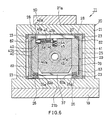
- Fig. 6 is an enlarged view in section taken along the line E-E in Fig. l;
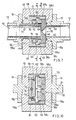
- Fig. 7 is an enlarged view in section taken along the line F-F in Fig. l;
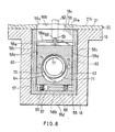
- Fig. 8 is a view in section taken along the line G-G in Fig. 7;
- Fig. 9 is a view in section taken along the line H-H in Fig. 7; and
- Fig. l0 is an enlarged view in section taken along the line I-I in Fig. l.
- The present invention will be described below in greater detail with reference to the accompanying drawings.
- Fig. l shows a horizontal pipe channel l0 of an orifice flowmeter and an orifice plate interchanging apparatus ll mounted on the channel. The channel l0 is provided by pipes l2, l3 and pipe flanges l4, l5, l6 and l7. A fluid is passed from the left side rightward in the drawing. The terms "front," "rear," "right" and "left" are hereinafter used with respect to the direction of flow of the fluid. More specifically stated with reference to Fig. l, the right side of the drawing is front, the left side is rear, the rear side of the plane of the drawing is left and the front side thereof is right.
- At an intermediate portion of the channel l0, a rectangular parallelepipedal first block l8 for installing an
orifice plate 39 therein is held between the two flanges l5, l6. A closedorifice plate stowage 20 positioned in parallel with the channel l0 is fixedly mounted on a flange l9 at the upper end of the block l8. - With reference to Figs. l to 3, 5 and 6, the
plate stowage 20 comprises a rectangular parallelepipedal main body 2l having an open rear end and aclosure 22 for closing the open end. The main body 2l is internally provided at its four corners with upper and lower opposed fourguides 23 extending along the channel l0 and has upper and lower twostoppers 24 at the front end of the body 2l inside thereof. A box-shaped rectagularparallelepipedal frame 25, which is open at its upper and lower sides, is secured to the front (inner) side of theclosure 22. Alower guide rail 26 extending longitudinally of the channel l0 is secured to each of the right and left sides of theframe 25 at its bottom. Anupper guide rail 27 projecting horizontally inward is integral with each of right and left sides of theframe 25 at its top. Theupper guide rail 27 is fixedly provided with a plurality ofshoes 28 on its upper side. While the stowage main body 2l has an upper wall 2la and a bottom wall 2lb, theframe 25 is inserted into the main body 2l along the upper wall lower surface, the bottom wall upper surface and theguides 23 and is positioned in place by these walls, the guides and thestoppers 24. With theframe 25 thus positioned in place, theclosure 22 is fixed to the stowage main body 2l to close the body. - A movable rack (body) 29 in the form of a rectangular parallelepipedal frame is provided between the
guide rails frame 25 and is slidable toward the front and rear. Themovable rack 29 has a pair of upperopposite shoes 82 and a pair of loweropposite shoes 83 extending longitudinally of the channel l0. A motor 3l for driving themovable rack 29 is fixedly provided within a closedcase 30 in front of theclosure 22 and has a shaft 3la fixedly carrying apulley 32. Arope 33 reeved around thepulley 32 has one end attached to the rear end of themovable rack 29, is passed around apulley 34 disposed at a rear portion of theframe 25 on the left side thereof and around twopulleys frame 25 and is connected at other end to the front end of therack 29. Themovable rack 29 has a plurality of (e.g. five)orifice plate bins 38 separated bypartition members 37 and arranged longitudinally of the rack (the channel) at a given spacing. Orificeplates 39 are stowed in thebins 38 respectively.Guide members 40, 4l are fixedly provided at the left and right sides of eachbin 38, respectively. The opposed guide faces 40a and 4la of the left andright guide members 40, 4l are on the same vertical plane as the opposed guide faces 83a of thelower shoes 83 and the opposed guide faces 26a of thelower guide rails 26 at the left and right sides of thestowage 20, respectively. At each of these sides, the guide faces provide a vertically continous face. Theleft guide member 40 is formed at its upper end an outwardlyrecessed portion 42 for locking the orifice plate. Thebottom face 42a of therecessed portion 42 is continuous with aslanting face 42b, which in turn is continuous with theguide face 40a - The
orifice plate 39 is generally rectangular parallelepipedal and has anorifice 43 in its center. The front-to-rear thickness of theorifice plate 39 is slightly smaller than the spacing between thepartition members 38. The right-to-left width of the plate is slightly smaller than the distance between theguide members 40, 4l. The height of the plate is smaller than the height of thebin 38. Anengaging cavity 44 is formed in the center of the upper end face of theorifice plate 39, with a coiledspring 45 attached to the bottom of thecavity 44. Theorifice plate 39 is formed, in an upper portion of its left end face, with astepped bore 46 extending into thecavity 44. A steppedpin 47 slightly longer than thebore 46 is inserted in the bore from the left side. A coiled spring 48 for biasing thepin 47 leftward is provided between the stepped portion of thebore 46 and the stepped portion of thepin 47. When theorifice plate 39 is stowed in thebin 38, the leftouter end 47a of thepin 47, projecting leftward, is fitted in therecessed portion 42 of theleft guide member 40, whereby theorifice plate 39 is locked (see Fig. 6). At this time, the rightinner end 47b of thepin 47 is in a retracted position within thebore 46. - The upper wall 2la of the stowage main body 2l has a guide bore 49 extending vertically therethrough approximately in its center. A cup-
shaped closure 50 is fixed to the upper side of the upper wall 2la for closing thebore 49. A device 5l for moving the orifice plate is provide at this portion. The device 5l comprises a lift rod (handling rod) 52 extending downward through the guide bore 49 and anair cylinder 84 for lifting and lowering therod 52. Theair cylinder 84 is fixed to the top of theclosure 50 as oriented vertically downward and has an unillustrated piston connected to thelift rod 52. Therod 52 extends downward through ahole 85 in the top wall of theclosure 50, with a packing 86 fitted in thehole 85 around therod 52. Atrapezoidal pushing plate 53 is secured to the lower end of thelift rod 52 on an outer side portion thereof. Apin 54 smaller than therod 52 in diameter integrally extends from the center of the lower end face of therod 52. An engagingflange 55 is integral with the lower end of thepin 54. Theflange 55 has an outside diameter smaller than the diameter of theupper end cavity 44 of theorifice plate 39. Although not shown, the plate moving device 5l has suitable means for rotating therod 52 through 90 degrees about its axis at a specified position as will be described later. - The bottom wall 2lb of the stowage main body 2l is formed with a
rectangular communication opening 56 for theorifice plate 39 to pass therethrough. Theopening 56 is defined by right and left opposed guide faces 56a and front and rear opposed guide faces 56b. At each of the right and left sides of theopening 56, theguide face 56a is flush and continuous with theguide face 26a of thelower guide rail 26 on the bottom wall 2lb. When each pair ofadjacent partition members 37 is positioned above theopening 56 as specified, theguide face 56b is flush with theguide face 37a of thepartition member 37 at each of front and rear sides of theopening 56. - The motor 3l moves the
movable rack 29 forward or rearward by one bin pitch or several bin pitches so as to position the desiredbin 38 between theopening 56 and thelift rod 52 in its raised position. The adjustment of such movement of themovable rack 29 and the replacement oforifice plates 39 can be made easily with theclosure 22 removed from the stowage main body 2l. - With reference to Figs. l, 2, 4 and 7 to l0, the first block l8 has a
cavity 57 extending to its bottom and having a rectangular horizontal section. Asecond block 58 for installing the orifice plate therein is fitted in thecavity 57. The first block l8 has a front wall l8a defining thecavity 57 and formed with acircular hole 59 concentric with the flange l5 fixed to the wall. The flange l5 has a rear portion fitted in thecircular hole 59 and a rear end face flush with the rear surface (guide face) l8b of the front wall l8a. An O-ring 60 is attached to the flange end face. The first block l8 has a rear wall l8c defining thecavity 57 and formed with a circular hole 6l concentric with the flange l6 fixed to the rear wall l8c. Thecommunication opening 56 of the main body 2l is opposed to the front portion of thecavity 57 of the first block l8. The front wall rear face l8b of the first block l8 is flush with thefront face 56b defining theopening 56. - The
second block 58 is so shaped as if it is prepared from a rectangular parallelepiped by cutting away its upper and front portions, leaving arear wall 58a, abottom wall 58b and opposite right and leftside walls 58c. The front portion of thebottom wall 58b is fixed to the bottom wall l8d of the first block l8 with bolts or the like. The front portions of the opposed surfaces of theside walls 58c of thesecond block 58 serve as guide faces 58d. At each of the right and left sides of theopening 56, theguide face 58d is flush and continuous with the opening-definingguide face 56a positioned immediately thereabove. Avertical guide groove 62 is formed in the rear portion of the inner surface of eachside wall 58c. Anorifice plate holder 63 in the form of a rectangular plate is fitted in theopposed grooves 63 at its lateral side rear portions and is slightly movable vertically and longitudinally of the channel ll. - Although the front portion of the
holder 63 is positioned between the guide faces 58d in front of thegrooves 62, theholder 63 is slightly movable transversely of the channel ll. Theholder 63 has ahole 64 in the form of a vertically elongated circle and is formed on the rear side of its lower portion a downwardly forwardlyslanting face 63a. At each of opposite lateral sides of theholder 63, arodlike projection 65 extends from its bottom face and is loosely fitted in adent 66 formed in the upper surface of thebottom wall 58b of thesecond block 58. Acoiled spring 67 is provided around theprojection 65 in pressing contact with the bottom face of theholder 63 and the bottom of thedent 66 for biasing theholder 63 upward. A horizontalforward extension 58e integral with the front portion upper end of therear wall 58a of thesecond block 58 extends over the entire length of this end for restraining theholder 63 from moving upward. Theextension 58e has at its midportion a cutout 68 for permitting the pushingplate 53 on thelift rod 52 to pass therethrough. - A square
shallow recess 69 is formed in the front surface of therear wall 58a of thesecond block 58. The bottom of the recessedportion 69 has acircular hole 70 approximately equal in diameter to the hole 6l in the rear wall l8c of the first block l8. A square pressing member 7l is loosely fitted in therecess 69 and loosely attached to the recessed bottom at its four corners withbolts 72. Acircular hole 73 slightly larger than thehole 70 of thesecond block 58 is formed in the pressing member 7l. Upper and lower short verticalsolid cylinders 74 are secured to the rear side of the member 7l, each with its rear half projecting from the rear surface. Thesecylinders 74 are fitted in upper and lower semicylindrical dents 75 formed in the bottom of the recessedportion 69, rendering the pressing member 7l slightly rotatable about thecylinders 74. Asemispherical projection 76 is provided on the front side of the pressing member 7l at each of its opposite lateral sides and is in contact with the slantingface 63a of theholder 63. - A
short pipe 77 is secured to the front side of the flange l6 on the rear wall l8c of the first block l8 concentrically with the flange l6. Theshort pipe 77 extends through theholes second block 58 and the pressing member 7l into thehole 64 of theholder 63. The distance between the front end of theshort pipe 77 and the rear surface l8b of the front wall of the first block l8 is slightly larger than the front-to-rear thickness of theorifice plate 39. - The first block front wall l8a defining the
cavity 57, theholder 63 and thebottom wall 58b and thelateral side walls 58c of thesecond block 58 define a space serving as an orificeplate mount portion 78. When theholder 63 moves downward, theprojections 76 on the pressing member 7l push theslanting face 63a, thereby moving theholder 63 forward, whereby the distance between the first block front wall l8a and theholder 63 is made slightly smaller than the front-to-rear thickness of theorifice plate 39. The distance becomes slightly larger than the orifice plate thickness when theholder 63 moves upward. - Pressure take-off
ports second block 58, respectively. A pressure take-off port 8l is also formed in the flange l5 on the first block front wall l8a. - The drawings show an
orifice plate 39 as installed in themount portion 78. In this state, thelift rod 52, extending through anempty bin 38 of themovable rack 29 and thecommunication opening 56 of the stowage main body 2l into the upper portion of thecavity 57 of the first block l8, has itsflange 55 positioned at the bottom portion of thecavity 44 in theorifice plate 39 within themount portion 78 to presss thecoiled spring 45 downward, whereby theorifice plate 39 is pressed against thebottom wall 58b of thesecond block 58. The leftouter end 47a of thepin 47 in theorifice plate 39 is in contact with theleft guide face 58d of the second block, and the rightinner pin end 47b is in an advanced position above theflange 55 in thecavity 44. The pushingplate 53 on thelift rod 52, passing through the cutout 68 in thesecond block 58, is oriented rearward and positioned below theextension 58e, pressing theholder 63 downward. Consequently, theholder 63, pressed forward by theprojections 76 on the pressing member 7l, holds the orifice plate in pressing contact with the rear end face of the flange l5. The pressing member 7l, which is slightly rotatable about thecylinders 74, is capable of pressing theentire holder 63 uniformly against theorifice plate 39. - For orifice plate changing, the
lift rod 52 is slowly raised first, whereby theholder 63 is slightly raised by being biased by thesprings 67 and is therefore released from the pressing force. When thelift rod 52 rises a predetermined amount, theflange 55 comes into engagement with the rightinner end 47b of thepin 47, raising theorifice plate 39. When the pushingplate 53 of thelift rod 52 has moved to a position above theextension 58e after passing through the cutout 68, the aforementioned rotating means rotates therod 52 through 90 degrees to direct the pushingplate 53 rightward withincavity 57. Further rise of thelift rod 52 moves theorifice plate 39 from themount portion 78 into theempty bin 38 of themovable rack 29 through theopening 56 of the stowage main body 2l. While theorifice plate 39 is being thus raised, the leftouter end 47a of thepin 47 comes into contact with theleft guide face 58d of thesecond block 58, the opening-definingleft guide face 56a, the guide faces 26a, 83a of the leftlower guide rail 26 and the leftlower shoe 83 and theleft guide face 40a of thebin 38 one after another, thereby always holding the rightinner pin end 47b in its advanced position within thecavity 44 in engagement with theflange 55 without allowing theorifice plate 39 to fall off under gravity. Upon theorifice plate 39 being completely placed into thebin 38, thepin 47 fits into the recessedportion 42 from theguide face 40a by being biased by the spring 48, thereby locking theorifice plate 39 in thebin 38. At the same time, the rightinner end 47b of thepin 47 retracts into thebore 46, releasing thelift rod 52 and permitting therod 52 alone to rise upward off theorifice plate 39. After thelift rod 52 has been brought to and stopped at a position above themovable rack 29 as indicated in a broken line in Fig. 3, themovable rack 29 moves to position theorifice plate 39 to be subsequently used immediately below thelift rod 52. Therod 52 then slowly lowers. With the descent of therod 52, theflange 55 enters thecavity 44 in theorifice plate 39 and depresses the coiledspring 45, thereby slowly lowering theorifice plate 39. Thepin 47 slides along from thebottom face 42a of the recessedportion 42 onto the slantingface 42b, moving rightward to come into contact with theguide face 40a off the recessedportion 42. This brings the rightinner end 47b of thepin 47 into theorifice plate cavity 44 to its advanced position above theflange 55, consequently obviating the likelihood of theplate 39 falling under gravity. Further descent of thelift rod 52 moves theorifice plate 39 out of thebin 38 into themount portion 78 through thecommunication opening 56 of the stowage main body 2l. The pushingplate 53 of thelift rod 52 moves down to an upper portion within thecavity 57 of the first block l8, whereupon the rotating means rotates therod 52 through 90 degrees to direct the pushingplate 53 rearward. Therod 52 thereafter further descends, bringing the pushingplate 53 to below the extension l8e through the cutout 68, thereby causing theflange 55 on therod 52 to depress thespring 45 in the bottom of theplate cavity 44 and forcing thepusing plate 53 to depress theholder 63. Consequently, theorifice plate 39 is pressed against thebottom wall 58b of thesecond block 39 and against the rear end face of the flange l5 in the same manner as already described and is thereby properly installed in themount portion 78. - The foregoing orifice plate changing operation can be carried out full-automatically using a computer or the like, selecting an
orifice plate 39 of optimal orifice size. Alternatively,orifice plates 39 can be interchanged semi-automatically through a manual procedure every time there arises a need to change plates. - Desired means is usable for lifting and lowering the
lift rod 52, as well as for rotating therod 52. Thelift rod 52 is rotatable in operative relation with the lifting-lowering movement, for example, using cams or the lile. Further thelift rod 52 is made manually movable from outside thestowage 20. The construction of the device 5l for moving the orifice plate is not limited to that of the foregoing embodiment but can be modified suitably. The movable rack (body) 29 and the moving means therefor can also be modified suitably. Therack 29 can be made manually movable from outside thestowage 20. Furthermore, theorifice plate 39,plate mount portion 78 and means for locking theorifice plate 39 in themount portion 78 are not limited to those of the foregoing embodiment but can be altered or modified suitably. The orifice plate interchanging apparatus described above is merely an illustrative embodiment of the invention and is in no way limitative.
Claims (7)
Priority Applications (1)
| Application Number | Priority Date | Filing Date | Title |
|---|---|---|---|
| AT87105738T ATE69500T1 (en) | 1986-04-18 | 1987-04-16 | DEVICE FOR REPLACING ORIFICES IN AN ORIFICE METER. |
Applications Claiming Priority (2)
| Application Number | Priority Date | Filing Date | Title |
|---|---|---|---|
| JP61090628A JP2524701B2 (en) | 1986-04-18 | 1986-04-18 | Orifice plate exchange device for throttle flow meter |
| JP90628/86 | 1986-04-18 |
Publications (3)
| Publication Number | Publication Date |
|---|---|
| EP0242825A2 true EP0242825A2 (en) | 1987-10-28 |
| EP0242825A3 EP0242825A3 (en) | 1989-10-11 |
| EP0242825B1 EP0242825B1 (en) | 1991-11-13 |
Family
ID=14003746
Family Applications (1)
| Application Number | Title | Priority Date | Filing Date |
|---|---|---|---|
| EP87105738A Expired EP0242825B1 (en) | 1986-04-18 | 1987-04-16 | Apparatus for interchanging orifice plates for orifice flowmeter |
Country Status (5)
| Country | Link |
|---|---|
| US (1) | US4750524A (en) |
| EP (1) | EP0242825B1 (en) |
| JP (1) | JP2524701B2 (en) |
| AT (1) | ATE69500T1 (en) |
| DE (1) | DE3774472D1 (en) |
Cited By (4)
| Publication number | Priority date | Publication date | Assignee | Title |
|---|---|---|---|---|
| EP0560303A2 (en) * | 1992-03-10 | 1993-09-15 | DANIEL INDUSTRIES, Inc. | Orifice system mounting assembly |
| EP0392271B1 (en) * | 1989-04-03 | 1993-09-29 | Landis & Gyr Business Support AG | Measuring device for fluid flow and/or quantities of heat |
| CN103822673A (en) * | 2013-12-11 | 2014-05-28 | 德阳市迪信佳阀门制造有限公司 | Valve-type orifice plate throttling device |
| EP3132233A1 (en) * | 2014-04-16 | 2017-02-22 | Dieterich Standard, Inc. | Flow meter |
Families Citing this family (7)
| Publication number | Priority date | Publication date | Assignee | Title |
|---|---|---|---|---|
| US5305796A (en) * | 1992-08-05 | 1994-04-26 | G-H Flow Automation, Inc. | Apparatus and method for centering an orifice plate |
| US6350086B1 (en) * | 2000-02-10 | 2002-02-26 | Eastman Chemical Company | Method and apparatus for establishing proper gas flow for unloading materials |
| US9454158B2 (en) | 2013-03-15 | 2016-09-27 | Bhushan Somani | Real time diagnostics for flow controller systems and methods |
| US9200650B2 (en) * | 2013-09-26 | 2015-12-01 | Paul D. Van Buskirk | Orifice plates |
| JP6498541B2 (en) * | 2015-06-16 | 2019-04-10 | 山洋電気株式会社 | measuring device |
| WO2016168326A1 (en) * | 2015-04-17 | 2016-10-20 | Daniel Measurement And Control, Inc. | Plate carrier guide for an orifice fitting |
| US10983537B2 (en) | 2017-02-27 | 2021-04-20 | Flow Devices And Systems Inc. | Systems and methods for flow sensor back pressure adjustment for mass flow controller |
Citations (2)
| Publication number | Priority date | Publication date | Assignee | Title |
|---|---|---|---|---|
| EP0092910A1 (en) * | 1982-03-29 | 1983-11-02 | Grove Valve And Regulator Company | Modular orifice meter with isolation chamber valve closure |
| EP0107328A2 (en) * | 1982-09-30 | 1984-05-02 | Grove Valve And Regulator Company | Orifice meter with pressure venting and equalizing safety device |
Family Cites Families (4)
| Publication number | Priority date | Publication date | Assignee | Title |
|---|---|---|---|---|
| US2031151A (en) * | 1935-03-15 | 1936-02-18 | Adam J Eulberg | Valve |
| US2820482A (en) * | 1954-12-03 | 1958-01-21 | Dolphice H Greenwood | Line blind gate valve |
| US4370893A (en) * | 1981-06-08 | 1983-02-01 | Grove Valve And Regulator Company | Orifice meter with replacable orifice disc |
| DE3227697C2 (en) * | 1982-07-24 | 1984-06-07 | C.H. Zikesch GmbH, 4100 Duisburg | Device for exchanging a measuring orifice switched on in a pipeline |
-
1986
- 1986-04-18 JP JP61090628A patent/JP2524701B2/en not_active Expired - Fee Related
-
1987
- 1987-04-16 AT AT87105738T patent/ATE69500T1/en not_active IP Right Cessation
- 1987-04-16 EP EP87105738A patent/EP0242825B1/en not_active Expired
- 1987-04-16 DE DE8787105738T patent/DE3774472D1/en not_active Expired - Fee Related
- 1987-04-17 US US07/039,334 patent/US4750524A/en not_active Expired - Lifetime
Patent Citations (2)
| Publication number | Priority date | Publication date | Assignee | Title |
|---|---|---|---|---|
| EP0092910A1 (en) * | 1982-03-29 | 1983-11-02 | Grove Valve And Regulator Company | Modular orifice meter with isolation chamber valve closure |
| EP0107328A2 (en) * | 1982-09-30 | 1984-05-02 | Grove Valve And Regulator Company | Orifice meter with pressure venting and equalizing safety device |
Cited By (7)
| Publication number | Priority date | Publication date | Assignee | Title |
|---|---|---|---|---|
| EP0392271B1 (en) * | 1989-04-03 | 1993-09-29 | Landis & Gyr Business Support AG | Measuring device for fluid flow and/or quantities of heat |
| EP0560303A2 (en) * | 1992-03-10 | 1993-09-15 | DANIEL INDUSTRIES, Inc. | Orifice system mounting assembly |
| EP0560303A3 (en) * | 1992-03-10 | 1995-05-10 | Daniel Ind Inc | Orifice system mounting assembly |
| CN103822673A (en) * | 2013-12-11 | 2014-05-28 | 德阳市迪信佳阀门制造有限公司 | Valve-type orifice plate throttling device |
| CN103822673B (en) * | 2013-12-11 | 2016-04-27 | 德阳市迪信佳阀门制造有限公司 | Valve-type orifice-plate restriction device |
| EP3132233A1 (en) * | 2014-04-16 | 2017-02-22 | Dieterich Standard, Inc. | Flow meter |
| EP3132233B1 (en) * | 2014-04-16 | 2022-12-28 | Dieterich Standard, Inc. | Flow meter |
Also Published As
| Publication number | Publication date |
|---|---|
| EP0242825B1 (en) | 1991-11-13 |
| EP0242825A3 (en) | 1989-10-11 |
| US4750524A (en) | 1988-06-14 |
| ATE69500T1 (en) | 1991-11-15 |
| JP2524701B2 (en) | 1996-08-14 |
| JPS62245923A (en) | 1987-10-27 |
| DE3774472D1 (en) | 1991-12-19 |
Similar Documents
| Publication | Publication Date | Title |
|---|---|---|
| EP0242825B1 (en) | Apparatus for interchanging orifice plates for orifice flowmeter | |
| US3887317A (en) | Pressing apparatus | |
| WO2022011997A1 (en) | Laser marking machine for embedding box | |
| CN212168631U (en) | Automatic bending machine | |
| CN210853563U (en) | Blood collection tube box for internal medicine | |
| US3727805A (en) | Mechanism for supporting a submerged pouring tube on a bottom-pour vessel and method of replacing tubes | |
| US3550924A (en) | Mechanism for controlling flow of liquid to a vacuum-treating vessel | |
| US2539615A (en) | Lubricant dispensing cabinet with elevators for plurality of pumps and vertically sliding front panel | |
| US3455084A (en) | Nursery stock packing device | |
| CN108133554B (en) | Mobile ticket box and ticket cabin for same | |
| US3602401A (en) | Volumetric measuring and dispensing device with scraper | |
| JP2741598B2 (en) | Equipment to facilitate the loading of compacted materials of waste | |
| CN211307595U (en) | Automatic edge folding equipment for paper card packaging box | |
| US5139664A (en) | Plate and cell holder | |
| CN209507006U (en) | Pusher equipment | |
| CN208774141U (en) | The stacking mechanism of carton automatic nailing machine | |
| CN106128989B (en) | A rewinding ware that is used for dislocation between silicon chip spool box to rewind | |
| US5037540A (en) | Plate and cell holder | |
| CN209095717U (en) | A kind of paper cutter with mobile platform | |
| CN216161306U (en) | Geologic structure evolution simulation device | |
| CN218665346U (en) | Linear cap screwing machine with positioning function | |
| CN209698867U (en) | A kind of steel plate cutting bed that can be positioned rapidly | |
| JP7108479B2 (en) | Container volume reduction device | |
| US4284203A (en) | Storage bin closure with liquid seal | |
| CN219216835U (en) | Sand shakeout device |
Legal Events
| Date | Code | Title | Description |
|---|---|---|---|
| PUAI | Public reference made under article 153(3) epc to a published international application that has entered the european phase |
Free format text: ORIGINAL CODE: 0009012 |
|
| AK | Designated contracting states |
Kind code of ref document: A2 Designated state(s): AT BE CH DE FR GB IT LI NL SE |
|
| PUAL | Search report despatched |
Free format text: ORIGINAL CODE: 0009013 |
|
| AK | Designated contracting states |
Kind code of ref document: A3 Designated state(s): AT BE CH DE FR GB IT LI NL SE |
|
| 17P | Request for examination filed |
Effective date: 19900216 |
|
| 17Q | First examination report despatched |
Effective date: 19910418 |
|
| GRAA | (expected) grant |
Free format text: ORIGINAL CODE: 0009210 |
|
| AK | Designated contracting states |
Kind code of ref document: B1 Designated state(s): AT BE CH DE FR GB IT LI NL SE |
|
| REF | Corresponds to: |
Ref document number: 69500 Country of ref document: AT Date of ref document: 19911115 Kind code of ref document: T |
|
| REF | Corresponds to: |
Ref document number: 3774472 Country of ref document: DE Date of ref document: 19911219 |
|
| ITF | It: translation for a ep patent filed |
Owner name: JACOBACCI & PERANI S.P.A. |
|
| ET | Fr: translation filed | ||
| PLBE | No opposition filed within time limit |
Free format text: ORIGINAL CODE: 0009261 |
|
| STAA | Information on the status of an ep patent application or granted ep patent |
Free format text: STATUS: NO OPPOSITION FILED WITHIN TIME LIMIT |
|
| 26N | No opposition filed | ||
| EAL | Se: european patent in force in sweden |
Ref document number: 87105738.6 |
|
| PGFP | Annual fee paid to national office [announced via postgrant information from national office to epo] |
Ref country code: DE Payment date: 20000224 Year of fee payment: 14 |
|
| PGFP | Annual fee paid to national office [announced via postgrant information from national office to epo] |
Ref country code: GB Payment date: 20000301 Year of fee payment: 14 |
|
| PGFP | Annual fee paid to national office [announced via postgrant information from national office to epo] |
Ref country code: FR Payment date: 20000320 Year of fee payment: 14 |
|
| PGFP | Annual fee paid to national office [announced via postgrant information from national office to epo] |
Ref country code: SE Payment date: 20000425 Year of fee payment: 14 Ref country code: CH Payment date: 20000425 Year of fee payment: 14 Ref country code: BE Payment date: 20000425 Year of fee payment: 14 Ref country code: AT Payment date: 20000425 Year of fee payment: 14 |
|
| PGFP | Annual fee paid to national office [announced via postgrant information from national office to epo] |
Ref country code: NL Payment date: 20000427 Year of fee payment: 14 |
|
| PG25 | Lapsed in a contracting state [announced via postgrant information from national office to epo] |
Ref country code: GB Free format text: LAPSE BECAUSE OF NON-PAYMENT OF DUE FEES Effective date: 20010416 Ref country code: AT Free format text: LAPSE BECAUSE OF NON-PAYMENT OF DUE FEES Effective date: 20010416 |
|
| PG25 | Lapsed in a contracting state [announced via postgrant information from national office to epo] |
Ref country code: SE Free format text: LAPSE BECAUSE OF NON-PAYMENT OF DUE FEES Effective date: 20010417 |
|
| PG25 | Lapsed in a contracting state [announced via postgrant information from national office to epo] |
Ref country code: FR Free format text: THE PATENT HAS BEEN ANNULLED BY A DECISION OF A NATIONAL AUTHORITY Effective date: 20010430 Ref country code: BE Free format text: LAPSE BECAUSE OF NON-PAYMENT OF DUE FEES Effective date: 20010430 |
|
| PG25 | Lapsed in a contracting state [announced via postgrant information from national office to epo] |
Ref country code: LI Free format text: LAPSE BECAUSE OF NON-PAYMENT OF DUE FEES Effective date: 20010515 Ref country code: CH Free format text: LAPSE BECAUSE OF NON-PAYMENT OF DUE FEES Effective date: 20010515 |
|
| BERE | Be: lapsed |
Owner name: FUJIKIN INTERNATIONAL INC. Effective date: 20010430 |
|
| PG25 | Lapsed in a contracting state [announced via postgrant information from national office to epo] |
Ref country code: NL Free format text: LAPSE BECAUSE OF NON-PAYMENT OF DUE FEES Effective date: 20011101 |
|
| EUG | Se: european patent has lapsed |
Ref document number: 87105738.6 |
|
| GBPC | Gb: european patent ceased through non-payment of renewal fee |
Effective date: 20010416 |
|
| REG | Reference to a national code |
Ref country code: CH Ref legal event code: PL |
|
| NLV4 | Nl: lapsed or anulled due to non-payment of the annual fee |
Effective date: 20011101 |
|
| PG25 | Lapsed in a contracting state [announced via postgrant information from national office to epo] |
Ref country code: DE Free format text: LAPSE BECAUSE OF NON-PAYMENT OF DUE FEES Effective date: 20020201 |
|
| REG | Reference to a national code |
Ref country code: FR Ref legal event code: ST |
|
| PG25 | Lapsed in a contracting state [announced via postgrant information from national office to epo] |
Ref country code: IT Free format text: LAPSE BECAUSE OF NON-PAYMENT OF DUE FEES;WARNING: LAPSES OF ITALIAN PATENTS WITH EFFECTIVE DATE BEFORE 2007 MAY HAVE OCCURRED AT ANY TIME BEFORE 2007. THE CORRECT EFFECTIVE DATE MAY BE DIFFERENT FROM THE ONE RECORDED. Effective date: 20050416 |