EP0242738B2 - Heat pipe - Google Patents
Heat pipe Download PDFInfo
- Publication number
- EP0242738B2 EP0242738B2 EP87105335A EP87105335A EP0242738B2 EP 0242738 B2 EP0242738 B2 EP 0242738B2 EP 87105335 A EP87105335 A EP 87105335A EP 87105335 A EP87105335 A EP 87105335A EP 0242738 B2 EP0242738 B2 EP 0242738B2
- Authority
- EP
- European Patent Office
- Prior art keywords
- container
- heat pipe
- main body
- porous block
- pipe
- Prior art date
- Legal status (The legal status is an assumption and is not a legal conclusion. Google has not performed a legal analysis and makes no representation as to the accuracy of the status listed.)
- Expired - Lifetime
Links
Images


Classifications
-
- C—CHEMISTRY; METALLURGY
- C07—ORGANIC CHEMISTRY
- C07D—HETEROCYCLIC COMPOUNDS
- C07D471/00—Heterocyclic compounds containing nitrogen atoms as the only ring hetero atoms in the condensed system, at least one ring being a six-membered ring with one nitrogen atom, not provided for by groups C07D451/00 - C07D463/00
- C07D471/02—Heterocyclic compounds containing nitrogen atoms as the only ring hetero atoms in the condensed system, at least one ring being a six-membered ring with one nitrogen atom, not provided for by groups C07D451/00 - C07D463/00 in which the condensed system contains two hetero rings
- C07D471/04—Ortho-condensed systems
-
- F—MECHANICAL ENGINEERING; LIGHTING; HEATING; WEAPONS; BLASTING
- F28—HEAT EXCHANGE IN GENERAL
- F28D—HEAT-EXCHANGE APPARATUS, NOT PROVIDED FOR IN ANOTHER SUBCLASS, IN WHICH THE HEAT-EXCHANGE MEDIA DO NOT COME INTO DIRECT CONTACT
- F28D15/00—Heat-exchange apparatus with the intermediate heat-transfer medium in closed tubes passing into or through the conduit walls ; Heat-exchange apparatus employing intermediate heat-transfer medium or bodies
- F28D15/02—Heat-exchange apparatus with the intermediate heat-transfer medium in closed tubes passing into or through the conduit walls ; Heat-exchange apparatus employing intermediate heat-transfer medium or bodies in which the medium condenses and evaporates, e.g. heat pipes
- F28D15/0258—Heat-exchange apparatus with the intermediate heat-transfer medium in closed tubes passing into or through the conduit walls ; Heat-exchange apparatus employing intermediate heat-transfer medium or bodies in which the medium condenses and evaporates, e.g. heat pipes with means to remove contaminants, e.g. getters
-
- Y—GENERAL TAGGING OF NEW TECHNOLOGICAL DEVELOPMENTS; GENERAL TAGGING OF CROSS-SECTIONAL TECHNOLOGIES SPANNING OVER SEVERAL SECTIONS OF THE IPC; TECHNICAL SUBJECTS COVERED BY FORMER USPC CROSS-REFERENCE ART COLLECTIONS [XRACs] AND DIGESTS
- Y10—TECHNICAL SUBJECTS COVERED BY FORMER USPC
- Y10S—TECHNICAL SUBJECTS COVERED BY FORMER USPC CROSS-REFERENCE ART COLLECTIONS [XRACs] AND DIGESTS
- Y10S165/00—Heat exchange
- Y10S165/917—Pressurization and/or degassification
Definitions
- the present invention relates to a heat pipe comprising a container comprising a container main body in the form of a pipe and an end cap closing each of opposite open ends of the main body having water enclosed therein as a working fluid and a solid agent in the portion thereof serving as its condensing portion and is made of iron reactive with water to evolve hydrogen gas.
- Heat pipes comprising an iron container having water enclosed therein as a working fluid are in wide use because of the high strength of the container and the high performance of water as the working fluid.
- heat pipes have the problem that iron reacts with water to evolve hydrogen gas, impairing the performance of the heat pipe in a short period of time. More specifically, the evolved hydrogen gas diffuses through the wall of the container in the form of atoms and becomes partly released from the container at a constant rate, but a major portion of the hydrogen gas remains in and occupies the condensing portion within the container to impede condensation of vapor and lower the performance of the heat pipe.
- Such impairment becomes pronounced with the time, rapidly shortening the life of the heat pipe.
- the iron container is sometimes aluminized over the outer surface to provide protection against corrosion and also to attach thereto aluminum fins having a brazing layer formed by vacuum brazing, the hydrogen gas diffusing through the container wall is then prevented from escaping from the container by the aluminized coating.
- the JP-A-61-85 95 describes a method for preventing a heat pipe from deteriorating even if the amount of generated hydrogen is high thereby improving the durability.
- At least part of all of the inner surface of a condensing section of a container is formed with a titanium covering layer.
- titanium has such properties that the hydrogen solubility is high but the hydrogen absorbed therein can be released easily, the hydrogen gas in the heat pipe can be quickly absorbed into the titanium coating layer due to the concentration gradient and can be transferred into the iron.
- hydrogen gas can be prevented from accumulating in the condensing section, and the safe operation can be done perpetually.
- one of several methods for the removal of hydrogen may comprise using copper oxide as a solid "absorption agent", wherein the reaction of copper oxide and water proceeds at 200°C.
- the hydrogen gas is oxidized to water by the copper oxide, with the result that the heat pipe can be prevented from deterioration due to the evolved hydrogen gas.
- the heat pipe has placed therein the copper oxide in such an amount as to oxidize the predicted total amount of hydrogen gas to be evolved, the heat pipe is operable reliably with the desired performance without impairment over a long period of time. An increased quantity of hydrogen gas will be produced when the heat pipe is used as a high temperature, but the gas can be returned to water rapidly to inhibit the deterioration of the heat pipe.
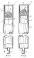
- Fig. 1 shows a first embodiment of the invention, i.e. a heat pipe, which comprises an iron container 1 having enclosed therein pure water (not shown) as a working fluid.
- the container 1 comprises a container main body 2 including a long pipe 3 made, for example, of iron STB35 prescribed in JIS (Japanese Industrial Standards) G3461 and a short pipe 4 welded to one end of the long pipe 3 and made, for example, of iron STB35.
- the container 1 further comprises an end cap 5 welded to one end of the container main body 2 and made, for example, of iron SS41 prescribed in JIS G3101, and another end cap 6 welded to the other end of the main body 2, having a nozzle 7 and made, for example, of iron SS41.
- the amount of pure water serving as the working fluid is preferably about 20% of the total interior volume of the container 1.
- a net 8 of a metal such as copper is provided within the short pipe 4 of the container 1 at a portion thereof toward the long pipe 3 to partition the interior of the short pipe 4 across the axis of the pipe.
- the peripheral edge of the net 8 is joined to the inner surface of the short pipe 4 by brazing the silver or the like.
- a granular copper oxide 9 for oxidizing hydrogen to water is placed in the space between the net 8 and the end cap 5.
- the size of the granules of the copper oxide 9 is larger than the mesh size of the net 8 so that the agent 9 will not pass through the meshes.
- the net 8 restrains the oxidizing agent 9 from moving toward the long pipe 3.
- the copper oxide used are Cu2O and CuO - in the following designated as "oxidizing agent" - which exert no adverse effect on the performance of the heat pipe when placed therein, are inexpensive and effectively oxidize hydrogen gas.
- the oxidizing agent 9 should be present in an amount sufficient to oxidize the hydrogen to be evolved within the heat pipe.
- a three-meter-long heat pipe in the form of an iron container having water enclosed therein up to 2 cm3/day of hydrogen gas is evolved even if the inner surface of the container is coated with a protective film. Accordingly, if this heat pipe is to be used for 10 years, 30 g of CuO (at least 0.32 mol) should be placed into the container.
- the heat pipe 1 is used with the short pipe side serving as a condensing portion and the opposite side as an evaporating portion.
- the hydrogen gas produced by the reaction of the working fluid, i.e. water, and the container 2 is oxidized to water by the oxidizing agent 9.
- Fig. 2 shows a second embodiment of the invention, i.e., a heat pipe comprising a container 11.
- the container 11 comprises a container main body 12 in the form of a pipe made, for example, of iron STB35 of JIS.
- a net 13 of a metal such as copper is provided within the container 11 at a portion thereof close to an end cap 5 to partition the interior of the main body 12.
- the peripheral portion of the net 13 is bent toward the other end of the main body 12 so as to extend along the inner surface of the main body 12.
- the bent edge portion 14 of the net is held between the container main body 12 and a ring 15 fixedly bearing against the inner surface of the main body 12, whereby the net 13 is secured to the container main body 12.
- a tube 21 for accommodating an oxidizing agent is provided within a container 11 at a position close to an end cap 5.
- One end of the tube 21 is welded to the inner surface of the end cap 5.
- the opening of the tube 21 at this end is closed with the cap 5.
- the other open end of the tube 21 is covered with a net 22 of a metal such as copper.
- the net is joined to the other end by brazing.
- the oxidizing agent 9 placed in the tube 21 is in the form of granules larger than the meshes of the net 22, which therefore prevents the agent 9 from moving toward the other end of the container 11.
- the oxidizing agent used in the first to third embodiments and in the form of granules may alternatively be a powder which is larger in particle size than the mesh size of the net.
- the container main body 2 comprises a long 3 and a short pipe 4 as in the first embodiment. Disposed within the short pipe 4 is a substantially spherical porous block 31 which is prepared by sintering a powdery oxidizing agent.
- a bar 32 parallel with the axis of the container main body 2 has one end secured to the inner surface of an end cap 5 and the other end fixedly provided with the porous body 31.
- the container main body 12 comprises a single pipe as is the case in the second embodiment.
- a tubular porous block 41 prepared by sintering a powdery oxidizing agent is provided within the container main body 12 at one end thereof close to an end cap 5 and is fixed to the main body 12.
- the block 41 is disposed concentrically within the container main body 12.
- the porous block 41 has an outside diameter slightly larger than the inside diameter of the main body 12 and is fitted into the main body 12 by force, whereby the block 41 is secured to the main body.
- the porous block 41 is fixed in position by making the outside diameter of the block 41 slightly smaller than the inside diameter of the main body 12, placing the block into the main body 41 and thereafter enlarging the porous block 41 radially outward into pressing contact with the inner surface of the main body 12.
- the container 1 shown is similar to that of the first embodiment and has, within a short pipe 4 at a position close to a long pipe 3, a restraining bar 51 intersecting the axis of the pipe 4 at right angles therewith.
- the spaces between the bar 51 and the inner peripheral surface of the short pipe 4 are smaller than a porous block 31 of oxidizing agent which is the same as the block 31 of the fourth embodiment.
- the porous block 31 is disposed between an end cap 5 and the restraining bar 51.
- the container main body 12 shown is similar to that of the second embodiment.
- the main body 12 has an enlarged portion 61 having a larger inside diameter, positioned close to an end cap 5 and formed by cutting the inner peripheral surface of the main body 12 over a specified length.
- a porous block 62 in the form of a solid cylinder and prepared by sintering a powdery oxidizing agent is accommodated in the enlarged portion 61.
- the porous block 61 has an outside diameter smaller than the inside diameter of the enlarged portion 61 but larger than the inside diameter of the other portion of the main body 12.
- a stepped portion 63 projecting inward from the inner peripheral surface of the enlarged portion 61 is formed on the inner surface of the main body 12 at the boundary between the enlarged portion 61 and the other portion.
- the stepped portion 63 prevents the porous block 62 from moving toward the other end of the main body 12.
- the container main body 12 shown is beaded at a specified distance from an end cap 5, whereby an annular inwardly projecting ridge 71 is formed over the entire inner peripheral surface of the main body 12.
- a solid cylindrical porous block 62 similar to the one included in the seventh embodiment and prepared by sintering a powdery oxidizing agent is disposed within the main body 12 between the ridge 71 and the end cap 5.
- the outside diameter of the porous body 62 is smaller than the inside diameter of the container main body 12 and larger than the inside diameter of the ridge 71.
- the ridge 71 on the inner surface of the container main body 12 prevents the porous block 62 from moving toward the other end of the main body 12.
- the ridge 71 serves as a step for restraining the porous block 62.
- the container main body 12 shown has placed therein a metal ring 81 at a specified distance from an end cap 5.
- the ring 81 is radially outwardly enlarged and is thereby secured to the main body 12.
- a solid cylindrical porous body 62 similar to that of the seventh embodiment and prepared by sintering a powdery oxidizing agent is disposed within the main body 12 between the ring 81 and the end cap 5.
- the porous block 62 has an outside diameter smaller than the inside diameter of the container main body 12 but larger than the inside diameter of the ring 81.
- the ring 81 on the inner surface of the main body 12 prevents the porous block 62 from moving toward the other end of the main body 12.
- the ring 81 serves as a stepped portion for preventing the movement of the porous block 62.
- the container main body 12 shown is radially enlarged over an end portion of specified length close to an end cap 5 to provide an enlarged portion 91.
- a solid cylindrical porous body 62 similar to that of the seventh embodiment and prepared by sintering a powdery oxidizing agent is accommodated in the enlarged portion 91.
- the porous block 62 has an outside diameter smaller than the inside diameter of the enlarged portion 91 but larger than the inside diameter of the other portion of the main body 12.
- An inclined stepped portion 92 inwardly projecting from the inner peripheral surface of the enlarged portion 91 and formed on the inner peripheral surface of the main body at the boundary between the portion 91 and the other portion prevents the porous block 62 from moving toward the other end of the container main body 12.
- the porous block 62 has an outside diameter smaller than the inside diameter of the short pipe 104 but larger than the inside diameter of the long pipe 103.
- the exposed end-face portion 105 of the long pipe 103 serves as a stepped portion for restraining the porous block 62 from moving toward the other end of the container main body 102.
- the container main body 12 shown and similar to that of the fifth embodiment has accommodated in one end portion thereof close to an end cap 5 a hollow cylindrical porous block 111 prepared by sintering a powdery oxidizing agent.
- the porous block 11 has a bore 112 extending therethrough in parallel with the axis of the main body 12.
- a bar 113 extending through the bore 112 has one end welded to the end cap 5 and the other end projecting out from the bore 112.
- a disklike stopper 114 is welded to the projecting end for restraining the porous block 111 from moving toward the other end of the main body 12.
- the disklike stopper 114 may be replaced by at least one rodlike stopper attached to the end of the bar 113.
- the second to twelfth embodiments are used with the oxidizing agent accommodating side serving as a condensing portion and the other side as an evaporating portion.
- the hydrogen gas resulting from the reaction of the working fluid, i.e. water, with the container is oxidized to water.
- the oxidizing agent is disposed in the condensing portion, but the agent need not always be positioned in this portion.
- a heat pipe having the construction of the first embodiment was used.
- Fig. 14 shows the result.
- a heat pipe having substantially the same construction as the pipe used in the above example was used except that no oxidizing agent was placed in the condensing portion.
- the pipe was checked for performance under the same conditions as above, with the result shown in Fig. 14.
Landscapes
- Chemical & Material Sciences (AREA)
- Organic Chemistry (AREA)
- Engineering & Computer Science (AREA)
- Life Sciences & Earth Sciences (AREA)
- Sustainable Development (AREA)
- Physics & Mathematics (AREA)
- Thermal Sciences (AREA)
- Mechanical Engineering (AREA)
- General Engineering & Computer Science (AREA)
- Sorption Type Refrigeration Machines (AREA)
- Powder Metallurgy (AREA)
- Devices And Processes Conducted In The Presence Of Fluids And Solid Particles (AREA)
Description
- The present invention relates to a heat pipe comprising a container comprising a container main body in the form of a pipe and an end cap closing each of opposite open ends of the main body having water enclosed therein as a working fluid and a solid agent in the portion thereof serving as its condensing portion and is made of iron reactive with water to evolve hydrogen gas.
- Heat pipes comprising an iron container having water enclosed therein as a working fluid are in wide use because of the high strength of the container and the high performance of water as the working fluid. However, such heat pipes have the problem that iron reacts with water to evolve hydrogen gas, impairing the performance of the heat pipe in a short period of time. More specifically, the evolved hydrogen gas diffuses through the wall of the container in the form of atoms and becomes partly released from the container at a constant rate, but a major portion of the hydrogen gas remains in and occupies the condensing portion within the container to impede condensation of vapor and lower the performance of the heat pipe. Such impairment becomes pronounced with the time, rapidly shortening the life of the heat pipe. While the iron container is sometimes aluminized over the outer surface to provide protection against corrosion and also to attach thereto aluminum fins having a brazing layer formed by vacuum brazing, the hydrogen gas diffusing through the container wall is then prevented from escaping from the container by the aluminized coating.
- The term "iron" as used herein includes pure iron and also iron alloys such as stainless steel and carbon steel.
- The JP-A-61-19 93 relates to a heat pipe containing water as a working fluid and a hydrogen preserving alloy such as Fe-Ti type or Mg-Ni type etc. in a vessel made of Al or its alloy. Hydrogen gas is generated by the reaction of Al and water which are composing materials of the vessel and hydrogen gas moves to the condensing part as a non-condensive gas and is absorbed by hydrogen preserving alloy without staying near by said part so the effective length of said condensing part of the heat pipe is not decreased, when the heat pipe composed of the above mentioned structure is operated for long time at 100° to 250°C.
- The JP-A-61-85 94 relates to a method of corrosion preventive treatment of the inner surface of the heat pipe by making a closed cylindrical vessel of a metal material mainly of iron such as carbon steels, chrome-nickel steels, chrome-nickel base stainless steels and so on. The wick made of a nonwoven fabric of metal fiber, organic fiber or inorganic fiber, a metal mesh or a porous sintered body produced from a metal powder which is pressed or baked onto the inner surface of the pipe.
- The JP-A-61-85 95 describes a method for preventing a heat pipe from deteriorating even if the amount of generated hydrogen is high thereby improving the durability. At least part of all of the inner surface of a condensing section of a container is formed with a titanium covering layer. As titanium has such properties that the hydrogen solubility is high but the hydrogen absorbed therein can be released easily, the hydrogen gas in the heat pipe can be quickly absorbed into the titanium coating layer due to the concentration gradient and can be transferred into the iron. As a result hydrogen gas can be prevented from accumulating in the condensing section, and the safe operation can be done perpetually. From Ullmanns Encyklopädie der technischen Chemie, 4th Edition, vol. 24, pages 316 to 318 and 346 it is known that one of several methods for the removal of hydrogen may comprise using copper oxide as a solid "absorption agent", wherein the reaction of copper oxide and water proceeds at 200°C.
- Accordingly, the following means have been employed to prevent the evolution of hydrogen gas and to preclude deterioration of the heat pipe due to the evolution of hydrogen gas.
- (1) Addition of an inhibitor to the working fluid, i.e. water to inhibit the reaction between water and iron.
- (2) Plating of the inner surface of the iron container with copper or light metal.
- (3) Provision of a hydrogen occluding material within the container.
- (4) Provision of a linear hydrogen passing member of Pd, or use of hydrogen-permeable Pd for forming the condensing portion to hold the interior of the container in communication with the outside.
- However, the means (1) and (2), if used, are unable to inhibit the evolution of hydrogen gas, while the means (3) and (4) fail to fully occlude or release hydrogen gas when the heat pipe is used at high temperatures which result in evolution of an increased amount of hydrogen gas. Accordingly, it has been impossible to prevent the heat pipe from deterioration even with the use of means (1) to (4).
- The main object of the present invention is to provide a heat pipe which is free of the foregoing problems and which retains the desired performance without deterioration over a prolonged period of time. The present invention provides a heat pipe comprising a container comprising a container main body in the form of a pipe and an end cap closing each of opposite open ends of the main body having water enclosed therein as a working fluid and a solid agent in the portion thereof serving as its condensing portion whereby the main body is made of a material reactive with water to evolve hydrogen gas, characterized in that the solid agent is a copper oxide and the main body is made of iron.
- According to the present invention, even when the working fluid, i.e. water, reacts with a container produce hydrogen gas, the hydrogen gas is oxidized to water by the copper oxide, with the result that the heat pipe can be prevented from deterioration due to the evolved hydrogen gas. Further when the heat pipe has placed therein the copper oxide in such an amount as to oxidize the predicted total amount of hydrogen gas to be evolved, the heat pipe is operable reliably with the desired performance without impairment over a long period of time. An increased quantity of hydrogen gas will be produced when the heat pipe is used as a high temperature, but the gas can be returned to water rapidly to inhibit the deterioration of the heat pipe.
- The present invention will be described in greater detail with reference to the accompanying drawings.
- Fig. 1 is a front view partly broken away and showing a first embodiment of heat pipe of the invention;
- Fig. 2 is a view similar to Fig. 1 and showing a second embodiment of the invention;
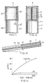
- Fig. 3 is a view in vertical section showing the condensing portion of a third embodiment of the invention;
- Fig. 4 is a view similar to Fig. 3 and showing a fourth embodiment of the invention;
- Fig. 5 is a view similar to Fig. 3 and showing a fifth embodiment of the invention;
- Fig. 6 is a view similar to Fig. 3 and showing a sixth embodiment of the invention;
- Fig. 7 is a view similar to Fig. 3 and showing a seventh embodiment of the invention;
- Fig. 8 is a view similar to Fig. 3 and showing an eighth embodiment of the invention;
- Fig. 9 is a view similar to Fig. 3 and showing a ninth embodiment of the invention;
- Fig. 10 is a view similar to Fig. 3 and showing a tenth embodiment of the invention;
- Fig. 11 is a view similar to Fig. 3 and showing an eleventh embodiment of the invention;
- Fig. 12 is a view similar to Fig. 3 and showing a twelfth embodiment of the invention;
- Fig. 13 is a front view partly broken away and showing a method of testing the heat pipe of Fig. 1 for the evaluation of its performance; and
- Fig. 14 is a graph showing the test result achieved by the heat pipe of Fig. 1 and the result attained by a comparative example.
- Throughout the drawings, like parts are designated by like reference numerals.
- Fig. 1 shows a first embodiment of the invention, i.e. a heat pipe, which comprises an
iron container 1 having enclosed therein pure water (not shown) as a working fluid. Thecontainer 1 comprises a containermain body 2 including along pipe 3 made, for example, of iron STB35 prescribed in JIS (Japanese Industrial Standards) G3461 and ashort pipe 4 welded to one end of thelong pipe 3 and made, for example, of iron STB35. Thecontainer 1 further comprises anend cap 5 welded to one end of the containermain body 2 and made, for example, of iron SS41 prescribed in JIS G3101, and anotherend cap 6 welded to the other end of themain body 2, having anozzle 7 and made, for example, of iron SS41. - The amount of pure water serving as the working fluid is preferably about 20% of the total interior volume of the
container 1. - A net 8 of a metal such as copper is provided within the
short pipe 4 of thecontainer 1 at a portion thereof toward thelong pipe 3 to partition the interior of theshort pipe 4 across the axis of the pipe. The peripheral edge of thenet 8 is joined to the inner surface of theshort pipe 4 by brazing the silver or the like. - A
granular copper oxide 9 for oxidizing hydrogen to water is placed in the space between the net 8 and theend cap 5. The size of the granules of thecopper oxide 9 is larger than the mesh size of thenet 8 so that theagent 9 will not pass through the meshes. Thus, the net 8 restrains the oxidizingagent 9 from moving toward thelong pipe 3. Examples of the copper oxide used are Cu₂O and CuO - in the following designated as "oxidizing agent" - which exert no adverse effect on the performance of the heat pipe when placed therein, are inexpensive and effectively oxidize hydrogen gas. - The oxidizing
agent 9 should be present in an amount sufficient to oxidize the hydrogen to be evolved within the heat pipe. For example, in a three-meter-long heat pipe in the form of an iron container having water enclosed therein, up to 2 cm³/day of hydrogen gas is evolved even if the inner surface of the container is coated with a protective film. Accordingly, if this heat pipe is to be used for 10 years, 30 g of CuO (at least 0.32 mol) should be placed into the container. - The
heat pipe 1 is used with the short pipe side serving as a condensing portion and the opposite side as an evaporating portion. The hydrogen gas produced by the reaction of the working fluid, i.e. water, and thecontainer 2 is oxidized to water by the oxidizingagent 9. - Fig. 2 shows a second embodiment of the invention, i.e., a heat pipe comprising a
container 11. Thecontainer 11 comprises a containermain body 12 in the form of a pipe made, for example, of iron STB35 of JIS. A net 13 of a metal such as copper is provided within thecontainer 11 at a portion thereof close to anend cap 5 to partition the interior of themain body 12. The peripheral portion of the net 13 is bent toward the other end of themain body 12 so as to extend along the inner surface of themain body 12. Thebent edge portion 14 of the net is held between the containermain body 12 and aring 15 fixedly bearing against the inner surface of themain body 12, whereby thenet 13 is secured to the containermain body 12. - Provided in the
container 11 between thenet 13 and theend cap 5 is anoxidizing agent 9 in the form of granules larger than the meshes of thenet 13. The net 13 prevents theoxidizing agent 9 from moving toward the other end of thecontainer 11. - With reference to Fig. 3 showing a third embodiment of the invention, a
tube 21 for accommodating an oxidizing agent is provided within acontainer 11 at a position close to anend cap 5. One end of thetube 21 is welded to the inner surface of theend cap 5. The opening of thetube 21 at this end is closed with thecap 5. The other open end of thetube 21 is covered with a net 22 of a metal such as copper. The net is joined to the other end by brazing. Theoxidizing agent 9 placed in thetube 21 is in the form of granules larger than the meshes of the net 22, which therefore prevents theagent 9 from moving toward the other end of thecontainer 11. - The oxidizing agent used in the first to third embodiments and in the form of granules may alternatively be a powder which is larger in particle size than the mesh size of the net.
- With reference to Fig. 4 showing a fourth embodiment of the invention, the container
main body 2 comprises a long 3 and ashort pipe 4 as in the first embodiment. Disposed within theshort pipe 4 is a substantially sphericalporous block 31 which is prepared by sintering a powdery oxidizing agent. Abar 32 parallel with the axis of the containermain body 2 has one end secured to the inner surface of anend cap 5 and the other end fixedly provided with theporous body 31. - With reference to Fig. 5 showing a fifth embodiment of the invention, the container
main body 12 comprises a single pipe as is the case in the second embodiment. A tubularporous block 41 prepared by sintering a powdery oxidizing agent is provided within the containermain body 12 at one end thereof close to anend cap 5 and is fixed to themain body 12. Theblock 41 is disposed concentrically within the containermain body 12. Theporous block 41 has an outside diameter slightly larger than the inside diameter of themain body 12 and is fitted into themain body 12 by force, whereby theblock 41 is secured to the main body. Alternatively, theporous block 41 is fixed in position by making the outside diameter of theblock 41 slightly smaller than the inside diameter of themain body 12, placing the block into themain body 41 and thereafter enlarging theporous block 41 radially outward into pressing contact with the inner surface of themain body 12. - With reference to Fig. 6 showing a sixth embodiment of the invention, the
container 1 shown is similar to that of the first embodiment and has, within ashort pipe 4 at a position close to along pipe 3, a restrainingbar 51 intersecting the axis of thepipe 4 at right angles therewith. The spaces between thebar 51 and the inner peripheral surface of theshort pipe 4 are smaller than aporous block 31 of oxidizing agent which is the same as theblock 31 of the fourth embodiment. Theporous block 31 is disposed between anend cap 5 and the restrainingbar 51. - With reference to Fig. 7 showing a seventh embodiment of the invention, the container
main body 12 shown is similar to that of the second embodiment. Themain body 12 has anenlarged portion 61 having a larger inside diameter, positioned close to anend cap 5 and formed by cutting the inner peripheral surface of themain body 12 over a specified length. Aporous block 62 in the form of a solid cylinder and prepared by sintering a powdery oxidizing agent is accommodated in theenlarged portion 61. Theporous block 61 has an outside diameter smaller than the inside diameter of theenlarged portion 61 but larger than the inside diameter of the other portion of themain body 12. A steppedportion 63 projecting inward from the inner peripheral surface of theenlarged portion 61 is formed on the inner surface of themain body 12 at the boundary between theenlarged portion 61 and the other portion. The steppedportion 63 prevents theporous block 62 from moving toward the other end of themain body 12. - With reference to Fig. 8 showing an eighth embodiment of the invention, the container
main body 12 shown is beaded at a specified distance from anend cap 5, whereby an annular inwardly projectingridge 71 is formed over the entire inner peripheral surface of themain body 12. A solid cylindricalporous block 62 similar to the one included in the seventh embodiment and prepared by sintering a powdery oxidizing agent is disposed within themain body 12 between theridge 71 and theend cap 5. The outside diameter of theporous body 62 is smaller than the inside diameter of the containermain body 12 and larger than the inside diameter of theridge 71. Theridge 71 on the inner surface of the containermain body 12 prevents theporous block 62 from moving toward the other end of themain body 12. Thus, theridge 71 serves as a step for restraining theporous block 62. - With reference to Fig. 9 showing a ninth embodiment of the invention, the container
main body 12 shown has placed therein ametal ring 81 at a specified distance from anend cap 5. Thering 81 is radially outwardly enlarged and is thereby secured to themain body 12. A solid cylindricalporous body 62 similar to that of the seventh embodiment and prepared by sintering a powdery oxidizing agent is disposed within themain body 12 between thering 81 and theend cap 5. Theporous block 62 has an outside diameter smaller than the inside diameter of the containermain body 12 but larger than the inside diameter of thering 81. Thering 81 on the inner surface of themain body 12 prevents theporous block 62 from moving toward the other end of themain body 12. Thus, thering 81 serves as a stepped portion for preventing the movement of theporous block 62. - With reference to Fig. 10 showing a tenth embodiment of the invention, the container
main body 12 shown is radially enlarged over an end portion of specified length close to anend cap 5 to provide anenlarged portion 91. A solid cylindricalporous body 62 similar to that of the seventh embodiment and prepared by sintering a powdery oxidizing agent is accommodated in theenlarged portion 91. Theporous block 62 has an outside diameter smaller than the inside diameter of theenlarged portion 91 but larger than the inside diameter of the other portion of themain body 12. An inclined steppedportion 92 inwardly projecting from the inner peripheral surface of theenlarged portion 91 and formed on the inner peripheral surface of the main body at the boundary between theportion 91 and the other portion prevents theporous block 62 from moving toward the other end of the containermain body 12. - With reference to Fig. 11 showing an eleventh embodiment of the invention, the
main body 102 of the container shown and indicated at 101 comprises long and short twopipes short pipe 104 has an inside diameter larger than the inside diameter of thelong pipe 103 but smaller than the outside diameter of thepipe 103. The portion of the end face of thelong pipe 103 including the inner peripheral edge thereof is exposed to the interior of theshort pipe 104. The exposed portion is indicated at 105. A solid cylindricalporous block 62 similar to that of the seventh embodiment and prepared by sintering a powdery oxidizing agent is accommodated in theshort pipe 104. Theporous block 62 has an outside diameter smaller than the inside diameter of theshort pipe 104 but larger than the inside diameter of thelong pipe 103. The exposed end-face portion 105 of thelong pipe 103 serves as a stepped portion for restraining theporous block 62 from moving toward the other end of the containermain body 102. - With reference to Fig. 12 showing a twelfth embodiment of the invention, the container
main body 12 shown and similar to that of the fifth embodiment has accommodated in one end portion thereof close to an end cap 5 a hollow cylindricalporous block 111 prepared by sintering a powdery oxidizing agent. Theporous block 11 has abore 112 extending therethrough in parallel with the axis of themain body 12. Abar 113 extending through thebore 112 has one end welded to theend cap 5 and the other end projecting out from thebore 112. Adisklike stopper 114 is welded to the projecting end for restraining theporous block 111 from moving toward the other end of themain body 12. - With this embodiment, the
disklike stopper 114 may be replaced by at least one rodlike stopper attached to the end of thebar 113. - The second to twelfth embodiments are used with the oxidizing agent accommodating side serving as a condensing portion and the other side as an evaporating portion. The hydrogen gas resulting from the reaction of the working fluid, i.e. water, with the container is oxidized to water.
- Although the embodiments described above are all of the wickless type, the present invention can be embodied as heat pipes having a wick.
- Further according to the foregoing embodiments, the oxidizing agent is disposed in the condensing portion, but the agent need not always be positioned in this portion.
- A heat pipe having the construction of the first embodiment was used.
- Prepared for the fabrication of the heat pipe were a
long pipe 3 measuring 31.8 mm in length, 4.5 mm in wall thickness and 2900 mm in length and made of iron STB35 prescribed in JIS G3461, and ashort pipe 4 measuring 31.8 mm in diameter, 4.5 mm in wall thickness and 100 mm in length and made of iron STB35. The inner surfaces of these pipes were brushed with a wire brush and thereafter degreased with acetone. A 80-mesh copper net 8 prescribed in JIS H6102 was blazed to the inner side of theshort pipe 4. Anoxidizing agent 9 comprising CuO and in the form of granules larger than the meshes of the net 8 was placed into theshort pipe 4. Anend cap 5 was then welded to one end of theshort pipe 4, and the other end of theshort pipe 4 was welded to one end of thelong pipe 3. Anend cap 6 provided with anozzle 7 was then welded to the other end of thelong pipe 3 to obtain acontainer 1. Pure water serving as a working fluid was enclosed in thecontainer 1 via thenozzle 7. Thus, the heat pipe was fabricated. - To check the heat pipe for performance, a water-cooling
jacket 121 was provided around one-half portion of the heat pipe toward its condensing side, and anelectric heater wire 122 was wound around the other half-portion of the pipe toward its evaporating side. Theheater wire 122 was then covered with aheat insulating material 123. The heat pipe was then installed as inclined by 6 degrees from a horizontal plane, with the end of the pipe at the condensing side positioned at a higher level (see Fig. 13). Cooling water was then passed through thejacket 121 to cool one half of the heat pipe, while heating the other half to 240°C with theheater wire 122. The temperature of the condensing portion at apoint P1 20 mm away from its outer end and the temperature of the pipe at the lengthwise midportion thereof outside thejacket 121, i.e. at a point P2 as shown in Fig. 13, were measured at a given time interval to determine the temperature difference ΔT between the two points P1 and P2. At this time, the amount of heat transfer from the evaporating portion to the condensing portion was adjusted to 4000 W at all times. Fig. 14 shows the result. - A heat pipe having substantially the same construction as the pipe used in the above example was used except that no oxidizing agent was placed in the condensing portion. The pipe was checked for performance under the same conditions as above, with the result shown in Fig. 14.
- The graph of Fig. 14 reveals that the product of the invention having the oxidizing
agent 9 placed in the condensing portion exhibits a temperature difference ΔT of about 3°C even after the lapse of 1000 hours and therefore remains satisfactory in heat transfer efficiency, whereas in the case of the comparative example, the temperature difference ΔT increases considerably, indicating that the heat transfer performance becomes impaired in a short period of time.
Claims (11)
- A heat pipe comprising a container (1,11) comprising a container main body (2,12) in the form of a pipe (3) and end caps (5,6) closing each of opposite open ends of the main body having water enclosed therein as a working fluid and a solid agent (9) in the portion thereof serving as its condensing portion whereby the main body is made of a material reactive with water to evolve hydrogen gas, characterized in that the solid agent is a copper oxide and the main body is made of iron.
- The heat pipe as defined in claim 1, wherein the copper oxide is granular.
- The heat pipe as defined in claim 1, wherein the copper oxide is powdery.
- The heat pipe as defined in claim 1, wherein a net (8) is provided within the container (1) and positioned at a specified distance from one end thereof for partitioning the interior of the container, and the copper oxide (9) is provided between the net and said one end of the container and is in the form of granules larger than the meshes of the net.
- The heat pipe as defined in claim 1, wherein the copper oxide (9) is powdery and sintered into a porous block (62), and the porous block is placed in the container (1).
- The heat pipe as defined in claim 5, wherein a bar (32) has one end secured to the inner surface of the end cap (5) at one end of the main body (2), the porous block (31) being fixed to the other end of the bar.
- The heat pipe as defined in claim 5, wherein the porous block (62) is in the form of a hollow cylinder (41) and is secured to the peripheral wall (12) of the container (11).
- The heat pipe as defined in claim 5, wherein the porous block (62) of copper oxide is disposed in an interior portion of the container (11) close to its one end, and restraining means (51, 63, 71, 81, 92, 105, 114) are provided within the container (1,11) at a specified distance from said one end thereof for restraining the porous block from moving toward the other end of the container.
- The heat pipe as defined in claim 8, wherein the restraining means is at least one bar (51) secured to the peripheral wall (2) of the container (1).
- The heat pipe as defined in claim 8, wherein the restraining means is a stepped portion (63,92) formed on the peripheral wall (12) of the container (11) and projecting inward from the inner peripheral surface of the container portion having the porous block (62) accommodated therein.
- The heat pipe as defined in claim 8, wherein the restraining means is a stopper (114) attached to one end of a bar (113), the bar extending through the porous block (111) and secured at the other end thereof to the end cap (5) at one end of the main body (12), the porous body being engageable with the stopper.
Applications Claiming Priority (10)
| Application Number | Priority Date | Filing Date | Title |
|---|---|---|---|
| JP61095391A JPH0678872B2 (en) | 1986-04-23 | 1986-04-23 | Heat pipe |
| JP95391/86 | 1986-04-23 | ||
| JP11559286U JPH037747Y2 (en) | 1986-07-28 | 1986-07-28 | |
| JP115590/86 | 1986-07-28 | ||
| JP115591/86 | 1986-07-28 | ||
| JP11559086U JPS6323569U (en) | 1986-07-28 | 1986-07-28 | |
| JP115589/86 | 1986-07-28 | ||
| JP11559186U JPH037746Y2 (en) | 1986-07-28 | 1986-07-28 | |
| JP115592/86 | 1986-07-28 | ||
| JP11558986U JPH037745Y2 (en) | 1986-07-28 | 1986-07-28 |
Publications (3)
| Publication Number | Publication Date |
|---|---|
| EP0242738A1 EP0242738A1 (en) | 1987-10-28 |
| EP0242738B1 EP0242738B1 (en) | 1989-11-08 |
| EP0242738B2 true EP0242738B2 (en) | 1995-01-11 |
Family
ID=27525743
Family Applications (1)
| Application Number | Title | Priority Date | Filing Date |
|---|---|---|---|
| EP87105335A Expired - Lifetime EP0242738B2 (en) | 1986-04-23 | 1987-04-10 | Heat pipe |
Country Status (5)
| Country | Link |
|---|---|
| US (1) | US4782890A (en) |
| EP (1) | EP0242738B2 (en) |
| CN (1) | CN1011538B (en) |
| CA (1) | CA1289129C (en) |
| DE (1) | DE3760977D1 (en) |
Families Citing this family (12)
| Publication number | Priority date | Publication date | Assignee | Title |
|---|---|---|---|---|
| JPH03501998A (en) * | 1988-10-19 | 1991-05-09 | エービービー エア プレヒーター インコーポレーテッド | Heat pipes using hydrogen oxidation means |
| US4884628A (en) * | 1988-10-19 | 1989-12-05 | En Jian Chen | Heat pipe employing hydrogen oxidation means |
| US4892142A (en) * | 1989-05-05 | 1990-01-09 | Luz Industries Israel, Ltd. | Device and method for removing gaseous impurities from a sealed vacuum |
| US5566751A (en) * | 1995-05-22 | 1996-10-22 | Thermacore, Inc. | Vented vapor source |
| US6209625B1 (en) * | 1999-06-14 | 2001-04-03 | Zhen Guo | Heat pipe with hydrogen getter |
| US8316927B2 (en) * | 2006-06-09 | 2012-11-27 | Denso Corporation | Loop heat pipe waste heat recovery device with pressure controlled mode valve |
| US20110108020A1 (en) * | 2009-11-11 | 2011-05-12 | Mcenerney Bryan William | Ballast member for reducing active volume of a vessel |
| US20110253126A1 (en) * | 2010-04-15 | 2011-10-20 | Huiming Yin | Net Zero Energy Building System |
| CN102285645B (en) * | 2011-06-17 | 2013-06-12 | 中国海洋石油总公司 | Heat pipe heat exchanger sulfur melting device and special heat pipe thereof |
| US9906001B2 (en) * | 2012-09-06 | 2018-02-27 | Abb Schweiz Ag | Passive cooling system for switchgear with star-shaped condenser |
| EP3601058B1 (en) | 2017-03-30 | 2025-06-18 | Shaw Industries Group, Inc. | Carpet tiles and systems and methods of making same |
| CN212931119U (en) * | 2020-08-03 | 2021-04-09 | 昆山联德电子科技有限公司 | Thin type temperature equalizing plate |
Family Cites Families (4)
| Publication number | Priority date | Publication date | Assignee | Title |
|---|---|---|---|---|
| SU517774A1 (en) * | 1975-02-04 | 1976-06-15 | Предприятие П/Я А-3521 | Heat pipe |
| NL8006608A (en) * | 1980-12-04 | 1982-07-01 | Philips Nv | SOLAR COLLECTOR. |
| NL8102467A (en) * | 1981-05-20 | 1982-12-16 | Philips Nv | HEAT TRANSPORTATION DEVICE WITH A CLOSED AND EVACUATED TUBE. |
| US4586561A (en) * | 1984-02-27 | 1986-05-06 | Exxon Research And Engineering Co. | Low temperature heat pipe employing a hydrogen getter |
-
1987
- 1987-04-10 EP EP87105335A patent/EP0242738B2/en not_active Expired - Lifetime
- 1987-04-10 DE DE8787105335T patent/DE3760977D1/en not_active Expired
- 1987-04-20 CN CN87103423A patent/CN1011538B/en not_active Expired
- 1987-04-20 US US07/039,856 patent/US4782890A/en not_active Expired - Lifetime
- 1987-04-22 CA CA000535243A patent/CA1289129C/en not_active Expired - Lifetime
Also Published As
| Publication number | Publication date |
|---|---|
| US4782890A (en) | 1988-11-08 |
| EP0242738A1 (en) | 1987-10-28 |
| CA1289129C (en) | 1991-09-17 |
| CN87103423A (en) | 1987-11-18 |
| CN1011538B (en) | 1991-02-06 |
| EP0242738B1 (en) | 1989-11-08 |
| DE3760977D1 (en) | 1989-12-14 |
Similar Documents
| Publication | Publication Date | Title |
|---|---|---|
| EP0242738B2 (en) | Heat pipe | |
| US4997124A (en) | Vacuum-insulated, double-walled metal structure and method for its production | |
| US4022662A (en) | Nuclear fuel element having a metal liner and a diffusion barrier | |
| ES2954274T3 (en) | Multi-layer composite fuel liner system with high temperature tightness and accident tolerance | |
| JP2543973B2 (en) | Fuel element with oxidation resistant coating | |
| EP0419159B1 (en) | Passive lower drywell flooder | |
| US2863816A (en) | Neutronic reactor fuel element | |
| IL45794A (en) | Nuclear fuel element | |
| JPS6119951B2 (en) | ||
| US4884628A (en) | Heat pipe employing hydrogen oxidation means | |
| JPS6029915B2 (en) | Composite cladding, fuel elements and manufacturing methods | |
| ES2275811T5 (en) | Zirconium alloy sheathed fuel rods containing metal oxide for secondary hybridization attenuation | |
| Elliott et al. | The oxidation of incoloy 800 in moist air containing HCl (g) at 800 C | |
| US4408655A (en) | Heat pipe | |
| JPS63129297A (en) | Heat pipe | |
| Peters et al. | A vapor pressure study of the alloys of manganese with copper | |
| JPH0645176Y2 (en) | heat pipe | |
| KR900702315A (en) | Heat pipes using hydrogen oxidation means | |
| JPH0547969Y2 (en) | ||
| JPH0666486A (en) | heat pipe | |
| JPS62252893A (en) | Heat pipe | |
| JP3136748B2 (en) | Heat insulation structure of inner wall such as piping | |
| CA1168225A (en) | Heat pipe | |
| JPS6239912B2 (en) | ||
| JPS58216988A (en) | Buried zirconium layer |
Legal Events
| Date | Code | Title | Description |
|---|---|---|---|
| PUAI | Public reference made under article 153(3) epc to a published international application that has entered the european phase |
Free format text: ORIGINAL CODE: 0009012 |
|
| AK | Designated contracting states |
Kind code of ref document: A1 Designated state(s): DE FR GB IT |
|
| 17P | Request for examination filed |
Effective date: 19880418 |
|
| 17Q | First examination report despatched |
Effective date: 19880805 |
|
| GRAA | (expected) grant |
Free format text: ORIGINAL CODE: 0009210 |
|
| AK | Designated contracting states |
Kind code of ref document: B1 Designated state(s): DE FR GB IT |
|
| REF | Corresponds to: |
Ref document number: 3760977 Country of ref document: DE Date of ref document: 19891214 |
|
| ET | Fr: translation filed | ||
| ITF | It: translation for a ep patent filed | ||
| PLBI | Opposition filed |
Free format text: ORIGINAL CODE: 0009260 |
|
| 26 | Opposition filed |
Opponent name: GEA LUFTKUEHLER GMBH Effective date: 19900808 |
|
| ITTA | It: last paid annual fee | ||
| PUAH | Patent maintained in amended form |
Free format text: ORIGINAL CODE: 0009272 |
|
| STAA | Information on the status of an ep patent application or granted ep patent |
Free format text: STATUS: PATENT MAINTAINED AS AMENDED |
|
| 27A | Patent maintained in amended form |
Effective date: 19950111 |
|
| AK | Designated contracting states |
Kind code of ref document: B2 Designated state(s): DE FR GB IT |
|
| ET3 | Fr: translation filed ** decision concerning opposition | ||
| ITF | It: translation for a ep patent filed | ||
| REG | Reference to a national code |
Ref country code: GB Ref legal event code: 732E |
|
| REG | Reference to a national code |
Ref country code: GB Ref legal event code: IF02 |
|
| REG | Reference to a national code |
Ref country code: FR Ref legal event code: TP |
|
| PGFP | Annual fee paid to national office [announced via postgrant information from national office to epo] |
Ref country code: GB Payment date: 20020405 Year of fee payment: 16 |
|
| PGFP | Annual fee paid to national office [announced via postgrant information from national office to epo] |
Ref country code: FR Payment date: 20020417 Year of fee payment: 16 |
|
| PGFP | Annual fee paid to national office [announced via postgrant information from national office to epo] |
Ref country code: DE Payment date: 20020426 Year of fee payment: 16 |
|
| PG25 | Lapsed in a contracting state [announced via postgrant information from national office to epo] |
Ref country code: GB Free format text: LAPSE BECAUSE OF NON-PAYMENT OF DUE FEES Effective date: 20030410 |
|
| PG25 | Lapsed in a contracting state [announced via postgrant information from national office to epo] |
Ref country code: DE Free format text: LAPSE BECAUSE OF NON-PAYMENT OF DUE FEES Effective date: 20031101 |
|
| GBPC | Gb: european patent ceased through non-payment of renewal fee |
Effective date: 20030410 |
|
| PG25 | Lapsed in a contracting state [announced via postgrant information from national office to epo] |
Ref country code: FR Free format text: LAPSE BECAUSE OF NON-PAYMENT OF DUE FEES Effective date: 20031231 |
|
| REG | Reference to a national code |
Ref country code: FR Ref legal event code: ST |
|
| PG25 | Lapsed in a contracting state [announced via postgrant information from national office to epo] |
Ref country code: IT Free format text: LAPSE BECAUSE OF NON-PAYMENT OF DUE FEES;WARNING: LAPSES OF ITALIAN PATENTS WITH EFFECTIVE DATE BEFORE 2007 MAY HAVE OCCURRED AT ANY TIME BEFORE 2007. THE CORRECT EFFECTIVE DATE MAY BE DIFFERENT FROM THE ONE RECORDED. Effective date: 20050410 |
|
| APAH | Appeal reference modified |
Free format text: ORIGINAL CODE: EPIDOSCREFNO |