EP0242435B1 - Closure for opening and closing side ring of chains for vehicle tyres - Google Patents
Closure for opening and closing side ring of chains for vehicle tyres Download PDFInfo
- Publication number
- EP0242435B1 EP0242435B1 EP86114216A EP86114216A EP0242435B1 EP 0242435 B1 EP0242435 B1 EP 0242435B1 EP 86114216 A EP86114216 A EP 86114216A EP 86114216 A EP86114216 A EP 86114216A EP 0242435 B1 EP0242435 B1 EP 0242435B1
- Authority
- EP
- European Patent Office
- Prior art keywords
- closure
- base body
- tongue
- opening
- hook
- Prior art date
- Legal status (The legal status is an assumption and is not a legal conclusion. Google has not performed a legal analysis and makes no representation as to the accuracy of the status listed.)
- Expired - Lifetime
Links
- 210000002105 tongue Anatomy 0.000 description 56
- 230000000694 effects Effects 0.000 description 5
- 230000006378 damage Effects 0.000 description 3
- 230000007423 decrease Effects 0.000 description 3
- 239000000463 material Substances 0.000 description 3
- 208000027418 Wounds and injury Diseases 0.000 description 2
- 238000010276 construction Methods 0.000 description 2
- 208000014674 injury Diseases 0.000 description 2
- 238000000034 method Methods 0.000 description 2
- 229910000831 Steel Inorganic materials 0.000 description 1
- 206010053648 Vascular occlusion Diseases 0.000 description 1
- 230000003247 decreasing effect Effects 0.000 description 1
- 238000003780 insertion Methods 0.000 description 1
- 230000037431 insertion Effects 0.000 description 1
- 239000002184 metal Substances 0.000 description 1
- 230000000630 rising effect Effects 0.000 description 1
- 239000010959 steel Substances 0.000 description 1
Images
Classifications
-
- B—PERFORMING OPERATIONS; TRANSPORTING
- B60—VEHICLES IN GENERAL
- B60C—VEHICLE TYRES; TYRE INFLATION; TYRE CHANGING; CONNECTING VALVES TO INFLATABLE ELASTIC BODIES IN GENERAL; DEVICES OR ARRANGEMENTS RELATED TO TYRES
- B60C27/00—Non-skid devices temporarily attachable to resilient tyres or resiliently-tyred wheels
- B60C27/06—Non-skid devices temporarily attachable to resilient tyres or resiliently-tyred wheels extending over the complete circumference of the tread, e.g. made of chains or cables
- B60C27/10—Non-skid devices temporarily attachable to resilient tyres or resiliently-tyred wheels extending over the complete circumference of the tread, e.g. made of chains or cables having tensioning means
-
- Y—GENERAL TAGGING OF NEW TECHNOLOGICAL DEVELOPMENTS; GENERAL TAGGING OF CROSS-SECTIONAL TECHNOLOGIES SPANNING OVER SEVERAL SECTIONS OF THE IPC; TECHNICAL SUBJECTS COVERED BY FORMER USPC CROSS-REFERENCE ART COLLECTIONS [XRACs] AND DIGESTS
- Y10—TECHNICAL SUBJECTS COVERED BY FORMER USPC
- Y10T—TECHNICAL SUBJECTS COVERED BY FORMER US CLASSIFICATION
- Y10T24/00—Buckles, buttons, clasps, etc.
- Y10T24/21—Strap tighteners
- Y10T24/2102—Cam lever and loop
- Y10T24/2119—Tie chain tighteners
-
- Y—GENERAL TAGGING OF NEW TECHNOLOGICAL DEVELOPMENTS; GENERAL TAGGING OF CROSS-SECTIONAL TECHNOLOGIES SPANNING OVER SEVERAL SECTIONS OF THE IPC; TECHNICAL SUBJECTS COVERED BY FORMER USPC CROSS-REFERENCE ART COLLECTIONS [XRACs] AND DIGESTS
- Y10—TECHNICAL SUBJECTS COVERED BY FORMER USPC
- Y10T—TECHNICAL SUBJECTS COVERED BY FORMER US CLASSIFICATION
- Y10T24/00—Buckles, buttons, clasps, etc.
- Y10T24/45—Separable-fastener or required component thereof [e.g., projection and cavity to complete interlock]
- Y10T24/45225—Separable-fastener or required component thereof [e.g., projection and cavity to complete interlock] including member having distinct formations and mating member selectively interlocking therewith
- Y10T24/45471—Projection having movable connection between components thereof or variable configuration
- Y10T24/45476—Projection having movable connection between components thereof or variable configuration with additional, similar projection for engaging different cavity
Definitions
- the invention relates to a closure for openable and closable side bars of anti-skid chains for vehicle tires according to the preamble of claim 1.
- closures for side brackets of anti-skid chains are known, the structure of the closures also depending in part on the construction used for the overall chain or the inner side bracket.
- Tension locks known that can be operated from the outside of the tire (tension chain locks). With such closures, it is avoided that the operator has to reach around the vehicle tire after closing the chain to close the closure; on the other hand, however, these fasteners have the disadvantage that after the first application and tightening, the vehicle has to be moved forward (even if only slightly), after which it is then necessary to retighten the fastener.
- closures which do not have to be operated from the outside of the tire and which consist essentially in the fact that two individual end pieces are provided which interlock in the closed position in a form-fitting manner.
- this looks like the one end piece is designed as a hook, the plane within which the hook shape is formed being directed essentially parallel to the clamping plane of the side bracket, while the other end piece is in the form of a correspondingly shaped eyelet, which is manual can be hooked into the hook.
- these known hook closures only lead to a secure locking effect if the eyelet does not lie on the back of the hook when the two elements are brought together, since then the desired hooking does not take place, which can occur with improper or careless use.
- the hooks are formed in that the base body of each end piece is bent at its end facing the other end piece in the form of a hook such that when the two end pieces converge during the closure movement, the two hooks run against one another with their round front sides and thereby the hooks are deflected in such a way that the two end pieces lying next to one another then carry out the remaining closing movement until the end piece lying on the tire flank engages with its hook in the hooking opening formed in the adjacent end piece.
- the known closure works safely and reliably, it has a relatively large overall width; should these be reduced so shapes are required ° requiring relatively complex shaped parts and thus a more complex structure.
- the invention is intended to further develop a closure of the type mentioned above in such a way that it has a particularly small width with a particularly simple construction. According to the invention, this is achieved with a closure of the type mentioned at the outset in that each hook is designed as a tongue which is folded out at a distance from the front end of the plate-shaped base body in the closing direction and obliquely against the closing direction of the closure.
- the closure according to the invention thus consists of two plate-shaped base bodies, the entire width (in the sense given above), ie the extent to which it is determined laterally away from the tire flank by the thickness of the plate-shaped base body and the tongue protruding therefrom. Since the tongue protrudes obliquely, it is no longer necessary, as in the case of the generic closure, to completely bend an entire section of the base body in the form of a hook.
- the obliquely opposite to the closing direction of the tongue ensures at the same time that during the closing movement when the two base bodies converge, one of them, depending on their relative position to one another, runs with its front end against the obliquely positioned tongue of the other and from the side thereof is deflected until it engages in the fastening opening on the other base body.
- an obliquely protruding tongue on the base body is possible in a particularly simple manner, preferably for example in that the tongue is in the form of a base body section which is folded out obliquely from the base body: all that is required is to pre-punch the tongue shape in the base body and then the pre-punched tongue out of the base body Fold out or bend out the basic body according to the desired bevel or inclined shape.
- the tongue protrudes obliquely from the base body, when inserting the edge of the hook opening in the other base body, which comes into contact with the tongue, triggers a certain "wedge” effect on the underside of the tongue, since this edge is drawn into the increasingly narrow gap between the underside of the tongue and the plane of the base body, which results in a somewhat more secure fit of the closure and a better security against an undesired opening of the same than when using a pure curved inside of the hook, which does not have such a "wedge” effect, the desired wedge effect on the one hand and the length of the tongue on the other hand by the choice a suitable angle of attack for the tongue can be optimized.
- each tongue is along a first, from Basic body outgoing tongue section is provided with an angle of attack to the closing direction of the closure, which is greater than the angle of attack of a subsequent second section of the tongue, which ends in the tongue end.
- the tongue protrusion required for the insertion of the hooking opening or the latching edge of the other base body can be created in a short way by the steeply rising first tongue section, after which a second section then follows, which essentially only covers the inserted section serves as a good hold.
- the angle of attack of the second section is significantly smaller than that of the first section, is preferably in a range between 0 ° and 20 ° (relative to the direction of closure of the closure), so that through this second, in the tongue end tapering tongue section good guidance and Support or mounting of the inserted portion of the other base body can be done without the width of the closure would be significantly increased by this overlap.
- the angle of rise in the first tongue section, which starts directly from the base body is preferably selected in a range from 45 ° to 70 ° , very particularly preferably around 60 ° .
- a very advantageous embodiment of the closure according to the invention also consists in the fact that both end pieces are mirror-symmetrical to one another, with very particular preference for each end piece also being designed symmetrically with respect to its longitudinal axis, which makes it possible to use end pieces of identical design.
- the shape of the tongues is preferably chosen such that they have a width that decreases continuously towards their free end, thereby ensuring that in the area that is most heavily loaded when hooking in (namely in the initial area behind the projecting point on Base body) have the greatest widths, while in the end region of the tongue, which only exerts an overlapping holding function, in which no large forces act, a decreasing width of the tongue is sufficient.
- the decrease in width can preferably be carried out in such a way that (seen in plan view of each tongue, i.e. in a viewing direction perpendicular to the base body) the free end of each tongue is rounded, particularly preferably rounded in the form of an ellipse.
- a very particularly preferred embodiment of the closure according to the invention can also be achieved in that each base body on the side on which its tongue is folded out is provided with a permanent magnet at a suitable point within the region which overlaps with the other base body in the closed state whose surface is flush with the surface of the end piece receiving it.
- a permanent magnet at a suitable point within the region which overlaps with the other base body in the closed state whose surface is flush with the surface of the end piece receiving it.
- the closure can, however, also be designed such that only one of the two base bodies again has a suitable permanent magnet at a suitable location within the area which overlaps with the other base body in the closed state, this time in a through opening of the base body receiving it is fastened so that it is flush with its two end faces with the surfaces of the two sides of this base body.
- This magnet can be effective on both sides of the body, i.e. it is ensured that this magnet is always so effective regardless of the position of the base body supporting it relative to the other base body (in the closed position) that it attracts the two bodies to one another.
- the point from which the tongue extends obliquely upwards from the corresponding base body can be provided in any desired, suitable position. So it can be advantageous under certain circumstances if the tongue projects as far as possible at the front end of the associated base body, so that the base body "begins" with the inclined tongue at its end facing the other base body. Equally, however, it may also be desirable to attach the tongue at a certain distance from the front end of the base body, especially if the tongue - as described - is folded out of the base body itself as an integral element, because this then results in a sufficiently large material cross section between the confluence of the Tongue is present in the base body and the corresponding ends so as not to trigger undesirable damage to the tongue.
- the design of the front end of each base body is preferably in the form of a curve, in order not only to avoid undesired edges and the possible risk of injury to the operator, but also to avoid them also in particular when the base bodies converge during the closing process to rule out the possibility that the two base bodies can come to a standstill with their front ends lying against one another.
- Fig. 1 shows a closure in the closed position with two end pieces 10, 11, each of which is fastened via suitable fasteners 12 to the ends 3 and 4 of side brackets of anti-skid chains (not shown). All suitable fastening means and fastening types which are known to the person skilled in the art and which need not be discussed in detail can be used for the fastening 12.
- the two end pieces 10 and 11 each have a plate-shaped base body 1 or 2, which is provided at its end opposite the attachment points 12 with a rounded shape C in plan view, oval in the illustrated embodiments.
- a tongue 7 or 8 is provided obliquely against the respective closing direction of the respective end piece 10 or 11.
- these tongues 7 and 8 consist of a section of the respective base body 1 or 2, which has been pre-punched in the base body and is then folded out or swung out in tongue-like fashion in the manner shown in the plane of the base body. As shown in FIG.
- the tongue 7 (the same also applies to the tongue 8) is initially set at an angle a in a first section 7a, which starts directly from the point of entry into the base body. This first section 7a is then followed by a second tongue section 7b, which runs out into the free end of the tongue and is set at a considerably smaller angle ⁇ , so that there is a "stepped" position as shown in FIG. 2 which is specifically referred to here.
- the angle a is preferably in a range from approximately 45 ° to 75 °
- the angle ⁇ is selected only in a range from 0 ° to 20 ° .
- each tongue end 14 , 15, for its part is rounded in plan view, preferably in the form of an elliptical section, as shown by arrow R in FIG. 3.
- each plate-shaped base body 1 or 2 shows that in addition to the tongues 7, 8, a hooking opening 5 or 6 is also formed in each plate-shaped base body 1 or 2.
- a hooking opening 5 or 6 is also formed in each plate-shaped base body 1 or 2.
- the relative position of the two end pieces 10 and 11 shown in the figures occurs, however, (seen in the direction of viewing of the viewer of the figures), the end piece 11 could equally be at the rear and the end piece 10 at the front.
- a permanent magnet 13 is also provided on each end piece 10 or 11 (shown in FIGS. 3 and 4 only at end piece 11) ), namely within area A (see FIG. 4), within which the two end pieces 10 and 11 overlap in the closed position.
- the permanent magnets 13 are placed in a suitable position between the respective tongue 7 or 8 and the hooking opening 6 of the relevant base body 1 or 2 in a receiving opening and fastened in a suitable manner (e.g. glued).
- the permanent magnet 13 is arranged as close as possible to the point at which the relevant tongue 7 or 8 runs out of the plane of the base body, so that the two end pieces 10 and 11 come into contact with one another as closely as possible, particularly in the tongue area.
- the permanent magnets 13 are each inserted into the respective base body 1 or 2 in such a way that their surface is flush with the corresponding surface 16 or 17 of the two plate-shaped base body 1 or 2 and does not protrude.
- the base bodies 1 and 2 are also rounded at their free ends with regard to their thickness, just as the end pieces 10 and 11 are designed in such a way that edges or corners are generally used be avoided.
- the base body can be made from any suitable steel sheet, but with the appropriate dimensions also from light metal or other suitable materials; The person skilled in the art is aware of the materials which can be used and he will select them accordingly.
Landscapes
- Engineering & Computer Science (AREA)
- Mechanical Engineering (AREA)
- Vehicle Step Arrangements And Article Storage (AREA)
- Buckles (AREA)
- Clamps And Clips (AREA)
- Slide Fasteners, Snap Fasteners, And Hook Fasteners (AREA)
- Seal Device For Vehicle (AREA)
- Hooks, Suction Cups, And Attachment By Adhesive Means (AREA)
- Fittings On The Vehicle Exterior For Carrying Loads, And Devices For Holding Or Mounting Articles (AREA)
- Lock And Its Accessories (AREA)
- Threshing Machine Elements (AREA)
Abstract
Description
Die Erfindung bezieht sich auf einen Verschluß für öffenbare und verschließbare Seitenbügel von Gleitschutzketten für Fahrzeugreifen gemäß dem Oberbegriff des Anspruches 1.The invention relates to a closure for openable and closable side bars of anti-skid chains for vehicle tires according to the preamble of
Es ist eine Vielzahl von Verschlüssen für Seitenbügel von Gleitschutzketten bekannt, wobei der Aufbau der Verschlüsse teilweise auch von der eingesetzten Konstruktion der Gesamtkette bzw. des inneren Seitenbügels abhängt. So sind z.B. Spannverschlüsse bekannt, die von der Reifenaußenseite her bedienbar sind (Spannkettenverschlüsse). Bei solchen Verschlüssen wird zwar vermieden, daß die Bedienungsperson nach dem Auflegen der Kette zum Schließen des Verschlusses um den Fahrzeugreifen herumgreifen muß; andererseits weisen diese Verschlüsse jedoch den Nachteil auf, daß nach dem ersten Aufbringen und Anziehen das Fahrzeug (wenn auch nur wenig) vorwärtsbewegt werden muß, wonach dann ein Nachspannen des Verschlusses erforderlich ist.A large number of closures for side brackets of anti-skid chains are known, the structure of the closures also depending in part on the construction used for the overall chain or the inner side bracket. For example, Tension locks known that can be operated from the outside of the tire (tension chain locks). With such closures, it is avoided that the operator has to reach around the vehicle tire after closing the chain to close the closure; on the other hand, however, these fasteners have the disadvantage that after the first application and tightening, the vehicle has to be moved forward (even if only slightly), after which it is then necessary to retighten the fastener.
Es sind aber auch andere Verschlüsse bekannt, die nicht von der Reifenaußenseite her bedient werden müssen und die im wesentlichen darin bestehen, daß zwei einzelne Endstücke vorgesehen sind, die in Verschlußstellung formschlüssig ineinander verhaken. In einfachster Ausgestaltung sieht dies so aus, daß das eine Endstück als Haken ausgebildet ist, wobei die Ebene, innerhalb derer die Hakenform ausgebildet ist, im wesentlichen parallel zur Aufspannebene des Seitenbügels gerichtet ist, während das andere Endstück als entsprechend geformte Öse vorliegt, die manuell in den Haken eingehängt werden kann. Daneben wurde aber auch schon vorgeschlagen, die Öse selbst als an der Reifenflanke anliegendes flächiges Element auszubilden und den Haken ebenfalls als flaches, aber senkrecht zur Ebene der Öse ausgebildetes Element vorzusehen. Diese bekannten Haken-Verschlüsse führen aber nur dann zu einer sicheren Verschließwirkung, wenn nicht die Öse beim Zusammenführen der beiden Elemente auf der Rückseite des Hakens liegt, da dann die gewünschte Verhakung nicht erfolgt, was bei unsachgemäßem oder unbedachtem Gebrauch durchaus eintreten kann.However, other closures are also known which do not have to be operated from the outside of the tire and which consist essentially in the fact that two individual end pieces are provided which interlock in the closed position in a form-fitting manner. In the simplest embodiment, this looks like the one end piece is designed as a hook, the plane within which the hook shape is formed being directed essentially parallel to the clamping plane of the side bracket, while the other end piece is in the form of a correspondingly shaped eyelet, which is manual can be hooked into the hook. In addition, however, it has also already been proposed to design the eyelet itself as a flat element lying against the tire flank and also to provide the hook as a flat element which is designed perpendicular to the plane of the eyelet. However, these known hook closures only lead to a secure locking effect if the eyelet does not lie on the back of the hook when the two elements are brought together, since then the desired hooking does not take place, which can occur with improper or careless use.
Um diesen Nachteil abzustellen, wurde bereits ein Hakenverschluß (EP-A 116 676) vorgeschlagen, bei dem die beiden an den Enden des Seitenbügels befestigten Endstücke jeweils sowohl einen Haken, wie auch noch eine Einhaköffnung aufweisen, so daß es bei der Verschlußbewegung unerheblich ist, wie sich die beiden Endstücke relativ zueinander in Verschlußstellung überdecken. Da dieses Endstück sowohl die Funktion eines Hakens, wie auch die einer Einhaköffnung übernehmen kann, ist eine Verschlußwirkung stets gewährleistet, unabhängig davon, wie die beiden Endstücke relativ nebeneinander bei der Verschlußbewegung zur Anordnung kommen. Bei diesem bekannten Verschluß werden die Haken dadurch ausgebildet, daß der Grundkörper jedes Endstücks an seinem dem anderen Endstück zugewendeten Ende in Form eines Hakens derart umgebogen ist, daß beim Zusammenlaufen der beiden Endstücke während der Verschlußbewegung die zwei Haken mit ihren runden Vorderseiten gegeneinander anlaufen und dadurch eine SfiJitlichs Ablenkung der Haken derart erfolgt, daß anschließend die beiden Endstücke nebeneinanderliegend die restliche Verschlußbewegung weiter ausführen, bis das an der Reifenflanke liegende Endstück mit seinem Haken in die im danebenliegenden Endstück ausgebildete Einhaköffnung eingreift. Obgleich der bekannte Verschluß sicher und zuverlässig arbeitet, weist er doch eine relativ große Gesamtbreite auf; soll diese reduziert werden, so sind Formgebungen erforderlich, °die relativ kompliziert geformte Einzelteile und damit einen aufwendigeren Aufbau erfordern.In order to remedy this disadvantage, a hook closure (EP-A 116 676) has already been proposed, in which the two end pieces attached to the ends of the side bracket each have both a hook and a hook opening, so that it is irrelevant during the closure movement, how the two end pieces overlap relative to each other in the closed position. Since this end piece can take on both the function of a hook and that of a hooking opening, a locking action is always guaranteed, regardless of how the two end pieces come to be arranged relatively next to one another during the locking movement. In this known closure, the hooks are formed in that the base body of each end piece is bent at its end facing the other end piece in the form of a hook such that when the two end pieces converge during the closure movement, the two hooks run against one another with their round front sides and thereby the hooks are deflected in such a way that the two end pieces lying next to one another then carry out the remaining closing movement until the end piece lying on the tire flank engages with its hook in the hooking opening formed in the adjacent end piece. Although the known closure works safely and reliably, it has a relatively large overall width; should these be reduced so shapes are required ° requiring relatively complex shaped parts and thus a more complex structure.
Da im Zuge der Entwicklung neuer Fahrzeuge immer weniger Raum zwischen den Reifenflanken einerseits und anderen mechanischen Elementen des Fahrzeugs andererseits zur Verfügung steht, so daß für des Anlegen einer Gleitschutzkette auch der Verscluß des inneren Seitenbügels eine möglichst geringe Verschlußbreite (d.h. seitliche Erstreckung von der Reifenflanke weg) aufweisen soll, soll die Erfindung einen Verschluß der vorstehend genannten Art derart weiterentwickeln, daß er eine besonders geringe Breite bei dennoch besonders einfachem Aufbau aufweist. Erfindungsgemäß wird dies bei einem Verschluß der eingangs genannten Art dadurch erreicht, daß jeder Haken als eine in einem Abstand von dem in Schließrichtung vorne liegenden Ende des plattenförmigen Grundkörpers aus diesem schräg entgegen der Schließrichtung des Verschlusses herausgeklappte Zunge ausgebildet ist.Since, in the course of the development of new vehicles, less and less space is available between the tire flanks on the one hand and other mechanical elements of the vehicle on the other hand, so that for the creation of an anti-skid chain, the closure of the inner side bracket has the smallest possible closure width (i.e. lateral extension away from the tire flank) ), the invention is intended to further develop a closure of the type mentioned above in such a way that it has a particularly small width with a particularly simple construction. According to the invention, this is achieved with a closure of the type mentioned at the outset in that each hook is designed as a tongue which is folded out at a distance from the front end of the plate-shaped base body in the closing direction and obliquely against the closing direction of the closure.
Der erfindungsgemäße Verschluß besteht somit aus zwei plattenförmigen Grundkörpern, deren gesamte Breite (im weiter oben angegebenen Sinne), d.h. deren Erstreckung seitlich von der Reifenflanke weg durch die Dicke des plattenförmigen Grundkörpers und die von diesem vorspringende Zunge bestimmt wird. Da die Zunge schräg vorspringt, ist es nicht mehr, wie beim gattungsgemäßen Verschluß, erforderlich, einen ganzen Abschnitt des Grundkörpers vollständig in Form eines Hakens umzubiegen. Durch die schräg entgegen der Schließrichtung verlaufende Ausbildung der Zunge wird aber gleichzeitig sichergestellt, daß während der Verschließbewegung beim Zusammenlaufen der beiden Grundkörper einer derselben, je nach ihrer relativen Lage zueinander, mit seinem vorderen Ende gegen die schräg angestellte Zunge des anderen anläuft und von dieser seitlich bis zu seinem Eingreifen in die Befestigungsöffnung am anderen Grundkörper abgelenkt wird. Das Anbringen einer schräg vorstehenden Zunge am Grundkörper ist in besonders einfacher Weise möglich, bevorzugt etwa dadurch, daß die Zunge als ein aus dem Grundkörper schräg herausgeklappter Grundkörperabschnitt besteht: hierzu ist es lediglich erforderlich, die Zungenform im Grundkörper vorzustanzen und dann die vorgestanzte Zunge aus dem Grundkörper entsprechend der gewünschten Schräge bzw. schrägen Formgebung herauszuklappen bzw. auszubiegen. Dadurch, daß die Zunge schräg vom Grundkörper vorspringt, wird beim Einführen der Kante der Einhaköffnung im anderen Grundkörper, die gegen die Zunge in Anlagekontakt kommt, auf der Unterseite der Zunge ein gewisser "Einkeil"-Effekt ausgelöst, da diese Kante in dem immer enger werdenden Spalt zwischen der Unterseite der Zunge und der Ebene des Grundkörpers hineingezogen wird, wodurch sich ein etwas sicherer Sitz des Verschlusses und eine bessere Sicherheit gegen ein unerwünschtes Öffnen desselben als bei Einsatz eines reinen auf seiner Innenseite gekrümmten Hakens ergibt, der einen solchen "Keil"-Effekt nicht aufweist, wobei der gewünschte Keil-Effekt einerseits und die Länge der Zunge andererseits durch die Wahl eines geeigneten Anstellwinkels für die Zunge optimiert werden können.The closure according to the invention thus consists of two plate-shaped base bodies, the entire width (in the sense given above), ie the extent to which it is determined laterally away from the tire flank by the thickness of the plate-shaped base body and the tongue protruding therefrom. Since the tongue protrudes obliquely, it is no longer necessary, as in the case of the generic closure, to completely bend an entire section of the base body in the form of a hook. The obliquely opposite to the closing direction of the tongue ensures at the same time that during the closing movement when the two base bodies converge, one of them, depending on their relative position to one another, runs with its front end against the obliquely positioned tongue of the other and from the side thereof is deflected until it engages in the fastening opening on the other base body. The attachment of an obliquely protruding tongue on the base body is possible in a particularly simple manner, preferably for example in that the tongue is in the form of a base body section which is folded out obliquely from the base body: all that is required is to pre-punch the tongue shape in the base body and then the pre-punched tongue out of the base body Fold out or bend out the basic body according to the desired bevel or inclined shape. Because the tongue protrudes obliquely from the base body, when inserting the edge of the hook opening in the other base body, which comes into contact with the tongue, triggers a certain "wedge" effect on the underside of the tongue, since this edge is drawn into the increasingly narrow gap between the underside of the tongue and the plane of the base body, which results in a somewhat more secure fit of the closure and a better security against an undesired opening of the same than when using a pure curved inside of the hook, which does not have such a "wedge" effect, the desired wedge effect on the one hand and the length of the tongue on the other hand by the choice a suitable angle of attack for the tongue can be optimized.
Um im Interesse eines guten Verrastungssitzes eine relativ große Überdeckung im Einhakungsbereich, d.h. zwischen der überstehenden Zunge einerseits und dem anderen Grundkörper andererseits zu erreichen und dennoch eine möglichst geringe Breite des Verschlusses zu erhalten, ist es besonders empfehlenswert, wenn jede Zunge längs eines ersten, vom Grundkörper ausgehenden Zungenabschnitts mit einem Anstellwinkel zur Schließrichtung des Verschlusses versehen ist, der größer ist als der Anstellwinkel eines sich anschließenden zweiten, in das Zungenende auslaufenden Abschnitts der Zunge. Durch diese Ausgestaltung kann durch den stärker ansteigenden ersten Zungenabschnitt auf kurzem Weg der erforderliche Zungenüberstand für das Einführen der Einhaköffnung bzw. deren Rastkante des anderen Grundkörpers gesschaffen werden, wonach sich dann ein zweiter Zu ngenabschnitt anschließt, der im wesentlichen nur mehr einer Überdeckung des eingeführten Abschnitts im Sinne eines guten Haltens dient. Dabei ist der Anstellwinkel des zweiten Abschnitts deutlich geringer als der des ersten Abschnitts, liegt vorzugsweise in einem Bereich zwischen 0° und 20° (relativ zur Verschließrichtung des Verschlusses gesehen), so daß durch diesen zweiten, in das Zungenende auslaufenden Zungenabschnitt eine gute Führung und Abstützung bzw. Halterung des eingeschobenen Abschnitts des anderen Grundkörpers erfolgen kann, ohne daß durch diese Überdeckung die Breite des Verschlusses nennenswert vergrößert würde. Bevorzugt wird der Anstiegswinkel in dem ersten Zungenabschnitt, der direkt vom Grundkörper ausgeht, in einem Bereich von 45° bis 70°, ganz besonders vorzugsweise um 60° gewählt.In order to achieve a relatively large overlap in the hooking area, i.e. between the protruding tongue on the one hand and the other base body on the other hand and to keep the width of the closure as small as possible in the interest of a good latching fit, it is particularly recommended if each tongue is along a first, from Basic body outgoing tongue section is provided with an angle of attack to the closing direction of the closure, which is greater than the angle of attack of a subsequent second section of the tongue, which ends in the tongue end. With this configuration, the tongue protrusion required for the insertion of the hooking opening or the latching edge of the other base body can be created in a short way by the steeply rising first tongue section, after which a second section then follows, which essentially only covers the inserted section serves as a good hold. The angle of attack of the second section is significantly smaller than that of the first section, is preferably in a range between 0 ° and 20 ° (relative to the direction of closure of the closure), so that through this second, in the tongue end tapering tongue section good guidance and Support or mounting of the inserted portion of the other base body can be done without the width of the closure would be significantly increased by this overlap. The angle of rise in the first tongue section, which starts directly from the base body, is preferably selected in a range from 45 ° to 70 ° , very particularly preferably around 60 ° .
Eine sehr vorteilhafte Ausgestaltung des erfindungsgemäßen Verschlusses besteht auch darin, daß beide Endstücke spiegelsymmetrisch zueinander ausgebildet sind, wobei ganz besonders bevorzugt jedes Endstück auch noch zu seiner Längsache symmetrisch gestaltet ist, was es möglicht, identisch zueinander ausgebildete Endstücke zu verwenden.A very advantageous embodiment of the closure according to the invention also consists in the fact that both end pieces are mirror-symmetrical to one another, with very particular preference for each end piece also being designed symmetrically with respect to its longitudinal axis, which makes it possible to use end pieces of identical design.
Bevorzugt wird weiterhin die Form der Zungen so gewählt, daß diese eine sich zu ihrem freien Ende hin laufend verringernde Breite aufweisen, wodurch sichergestellt wird, daß in gerade dem Bereich, der beim Einhaken am stärksten belaster wird (nämlich im anfänglichen Bereich hinter der Vorspringstelle am Grundkörper) die größten Breiten vorliegen, während im Endbereich der Zunge, der nur noch eine überdeckende Haltefunktoin ausübt, bei der keine großen Kräfte wirksam werden, eine abnehmende Breite der Zunge genügt. Die Breitenabnahme kann dabei vorzugsweise so erfolgen, daß (in der Draufsicht auf jede Zunge gesehen, d.h. in einer Blickrichtung senkrecht zum Grundkörper hin) das freie Ende jeder Zunge abgerundet, besonders vorzugsweise ellipsenabschnittförmig gerundet ist. Hierdurch wird nicht nur ein gefälliges Aussehen erreicht, sondern es werden auch unnötige Kanten bzw. Ecken vermieden, die unter ungünstigen Verhältnissen beim Betätigen des Verschlusses zu einer Verletzungsgefahr führen könnten.Furthermore, the shape of the tongues is preferably chosen such that they have a width that decreases continuously towards their free end, thereby ensuring that in the area that is most heavily loaded when hooking in (namely in the initial area behind the projecting point on Base body) have the greatest widths, while in the end region of the tongue, which only exerts an overlapping holding function, in which no large forces act, a decreasing width of the tongue is sufficient. The decrease in width can preferably be carried out in such a way that (seen in plan view of each tongue, i.e. in a viewing direction perpendicular to the base body) the free end of each tongue is rounded, particularly preferably rounded in the form of an ellipse. As a result, not only is a pleasing appearance achieved, but unnecessary edges or corners are also avoided, which, under unfavorable conditions, could lead to a risk of injury when the closure is actuated.
Eine ganz besonders vorzugsweise Ausgestaltung des erfindungsgemäßen Verschlusses läßt sich auch dadurch erreichen, daß jeder Grundkörper auf der Seite, auf der seine Zunge ausgeklappt ist, innerhalb des Bereiches, der sich im Schließzustand mit dem anderen Grundkörper überdeckt, an geeigneter Stelle mit einem Permanentmagneten versehen ist, dessen Oberfläche mit der Oberfläche des ihn aufnehmenden Endstücks bündig abschließt. Hierdurch wird noch zusätzlich ein "Anziehungs"-Effekt erreicht, indem im Verschlußzustand die beiden nebeneinanderliegenden Grundkörper durch den Magneten des Grundkörpers, der den Haken für den Einhakvorgang ausbildet, aneinandergezogen und dadurch ein besonders fester Sitz und eine gute Sicherung gegen unerwünschtes Öffnen erzielt wird.A very particularly preferred embodiment of the closure according to the invention can also be achieved in that each base body on the side on which its tongue is folded out is provided with a permanent magnet at a suitable point within the region which overlaps with the other base body in the closed state whose surface is flush with the surface of the end piece receiving it. As a result, an additional “attraction” effect is achieved in that, in the closed state, the two adjacent base bodies are pulled together by the magnet of the base body that forms the hook for the hooking-in process, thereby achieving a particularly tight fit and good protection against unwanted opening.
In einer anderen, ebenfalls vorzugsweisen Ausgestaltung der Erfindung kann der Verschluß jedoch auch so ausgebildet sein, daß nur einer der beiden Grundkörper wiederum innerhalb des Bereiches, der sich im Schließzustand mit dem anderen Grundkörper überdeckt, an geeigneter Stelle einen geeigneten Permanentmagneten aufweist, der diesmal in einer durchgehenden Öffnung des ihn aufnehmenden Grundkörpers so befestigt ist, daß er mit seinen beiden Endflächen bündig mit den Oberflächen der beiden Seiten dieses Grundkörpers abschließt. Dieser Magnet kann auf beide Seiten des Grundkörpers wirksam sein, d.h. es ist sichergestellt, daß dieser Magnet ungeachtet der Lage des ihn tragenden Grundkörpers relativ zum anderen Grundkörper (in Versclußstellung) stets so wirksam ist, daß er die beiden Körper aneinander anzieht.In another, also preferred embodiment of the invention, the closure can, however, also be designed such that only one of the two base bodies again has a suitable permanent magnet at a suitable location within the area which overlaps with the other base body in the closed state, this time in a through opening of the base body receiving it is fastened so that it is flush with its two end faces with the surfaces of the two sides of this base body. This magnet can be effective on both sides of the body, i.e. it is ensured that this magnet is always so effective regardless of the position of the base body supporting it relative to the other base body (in the closed position) that it attracts the two bodies to one another.
Die Stelle, von der aus die Zunge jeweils vom entsprechenden Grundkörper schräg nach oben abgeht, kann in jeder gewünschten, geeigneten Position vorgesehen werden. So kann es unter bestimmten Umständen vorteilhaft sein, wenn die Zunge möglichst weit am vorderen Ende des zugehörigen Grundkörpers vorspringt, so daß der Grundkörper an seinem dem anderen Grundkörper zugewendeten Ende gleichsam mit der schräg ansteigenden Zunge "beginnt". Gleichermaßen kann es jedoch auch wünschenswert sein, die Zunge in einem gewissen Abstand vom vorderen Ende des Grundkörpers anzubringen, insbesondere dann, wenn die Zunge - wie geschildert - als einstückiges Element des Grundkörpers selbst aus diesem herausgeklappt wird, weil hierdurch dann ein ausreichend großer Materialquerschnitt zwischen der Einmündungsstelle der Zunge in den Grundkörper und den entsprechenden Enden vorliegt, um nicht ein unerwünschtes Beschädigen der Zunge auszulösen. In diesem Fall kann es ferner vorteilhaft sein, das vordere Ende des Grundkörpers selbst in geeigneter Weise auch über dessen Plattendicke hinweg abzurunden, damit die solchermaßen gegeneinander beim Verschluß anlaufenden vorderen Grundkörperenden sich ebenfalls seitlich ablenken können. Überhaupt ist die Ausbildung desr vorderen Endes jedes Grundkörpers vorzugsweise ebenso wie die der Zunge (in senkrechter Draufsicht auf den Grundkörper gesehen) in Form einer Rundung ausgeführt, um auch hier nicht nur unerwünschte Kanten und damit ausgelöste mögliche Verletzungsgefahren für die Bedienungsperson zu vermeiden, sondern um auch insbesondere beim Zusammenlaufen der Grundkörper während des Verschließvorganges die Möglichkeit auszuschließen, daß die beiden Grundkörper mit ihren vorderen Enden aneinanderliegend zum Stillstand kommen können.The point from which the tongue extends obliquely upwards from the corresponding base body can be provided in any desired, suitable position. So it can be advantageous under certain circumstances if the tongue projects as far as possible at the front end of the associated base body, so that the base body "begins" with the inclined tongue at its end facing the other base body. Equally, however, it may also be desirable to attach the tongue at a certain distance from the front end of the base body, especially if the tongue - as described - is folded out of the base body itself as an integral element, because this then results in a sufficiently large material cross section between the confluence of the Tongue is present in the base body and the corresponding ends so as not to trigger undesirable damage to the tongue. In this case, it can also be advantageous to round off the front end of the base body itself in a suitable manner over its plate thickness, so that the front base body ends thus running against one another during the closure can likewise be deflected laterally. In general, the design of the front end of each base body, like that of the tongue (seen in a vertical plan view of the base body), is preferably in the form of a curve, in order not only to avoid undesired edges and the possible risk of injury to the operator, but also to avoid them also in particular when the base bodies converge during the closing process to rule out the possibility that the two base bodies can come to a standstill with their front ends lying against one another.
Die Erfindung wird nachfolgend anhand der Zeichnung im Prinzip beispielshalber noch näher erläutert. Es zeigen:
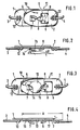
- Fig. 1 einen erfindungsgemäßen Verschluß in Verschließstellung (in perspektivischer Draufsicht);
- Fig. 2 eine Draufsicht auf den in Fig. 1 dargestellten Verschluß (Blickrichtung um 90° gedreht);
- Fig. 3 eine andere Ausführungsform eines erfindungsgemäßen Verschlusses mit Permanentmagneten (in Verschließstellung), und
- Fig. 4 ein Draufsicht auf den in Fig. 3 dargestellten Verschluß (Blickrichtung um 90° gedreht).
- 1 shows a closure according to the invention in the closed position (in a perspective top view);
- FIG. 2 shows a plan view of the closure shown in FIG. 1 (viewing direction rotated by 90 ° );
- Fig. 3 shows another embodiment of a closure according to the invention with permanent magnets (in the closed position), and
- Fig. 4 is a plan view of the closure shown in Fig. 3 (viewing direction rotated by 90 ° ).
Fig. 1 zeigt einen Verschluß in Verschlußstellung mit zwei Endstücken 10, 11, deren jedes über geeignete Befestigungen 12 an den Enden 3 bzw. 4 von Seitenbügeln von (nicht gezeigten) Gleitschutzketten befestigt ist. Für die Befestigung 12 können dabei alle geeigneten Befestigungsmittel und Befestigungsarten, die dem Fachmann bekannt sind und auf die nicht näher einzugehen ist, eingesetzt werden.Fig. 1 shows a closure in the closed position with two
Die beiden Endstücke 10 bzw. 11 weisen jeweils einen plattenförmigen Grundkörper 1 bzw. 2 auf, der an seinem den Befestigungsstellen 12 entgegengesetztem Ende mit einer in Draufsicht abgerundeten, bei den dargestellten Ausführungsbeispielen ovalen Formgebung C versehen ist. In einem gewissen Abstand jeweils von diesem Ende jedes plattenförmigen Grundkörpers 1 bzw. 2 ist eine schräg entgegen der jeweiligen Schließrichtung des betreffenden Endstückes 10 bzw. 11 angestellte Zunge 7 bzw. 8 vorgesehen. Wie die Figuren zeigen, bestehen diese Zungen 7 bzw. 8 aus einem Abschnitt des jeweiligen Grundkörpers 1 bzw. 2, der im Grundkörper vorgestanzt wurde und dann zungenförmig in der dargestellten Art und Weise aus der Ebene des Grundkörpers herausgeklappt bzw. herausgeschwenkt ist. Wie Fig. 2 zeigt, ist dabei die Zunge 7 (gleiches gilt auch für die Zunge 8) zunächst in einem ersten Abschnitt 7a, der unmittelbar von der Stelle der Einmündung in den Grundkörper ausgeht, unter einem Winkel a angestellt. An diesem ersten Abschnitt 7a schließt sich sodann ein zweiter Zungenabschnitt 7b an, der in das freie Ende der Zunge ausläuft und in einem erheblich kleineren Winkel β angestellt ist, so das sich eine "gestufte" Anstellung gemäß der Darstellung in Fig. 2 ergibt, auf die hier audrücklich verwiesen wird. Der Winkel a liegt dabei vorzugsweise in einem Bereich von etwa 45° bis 75°, während der Winkel β nur in einem Bereich von 0° bis 20° gewält wird.The two
Wie alle Figuren deutlich darstellen, sind die Zungen 7 bzw. 8 in der Draufsicht so ausgebildet, daß ihre Breite B (vgl. Fig. 1) kontinuierlich bis zum jeweiligen Zungenende 14 bzw. 15 (Fig. 3) abnimmt, wobei jedes Zungenende 14, 15 seinerseits in der Draufsicht abgerundet, vorzugsweise ellipsenabschnittförmig gestaltet ist, wie dies in Fig. 3 durch Pfeil R dargestellt wird.As clearly shown in the figures, the
Die Figuren lassen ferner erkennen, daß neben den Zungen 7, 8 in jedem plattenförmigen Grundkörper 1 bzw. 2 auch jeweils eine Einhaköffnung 5 bzw. 6 ausgebildet ist. In Verschlußstellung tritt dabei die in den Figuren dargestellte Relativlage der beiden Endstücke 10 bzw. 11 auf, wobei jedoch (in Blickrichtung des Betrachters der Figuren gesehen) gleichermaßen auch das Endstück 11 hinten und das Endstück 10 vorne liegen könnte. In jedem Fall ist gewährleistet, daß das hinten liegende Endstück (in den Figuren: das Endstück 10), das an der (nicht gezeigten) Flanke des Reifens liegt, über den die mit diesem Verschluß versehene Gleitschutzkette übergestülpt ist, mit seiner Zunge (im gezeigten Fall: mit der Zunge 8) durch die entsprechende Einhaköffnung 6 des anderen Endstücks 11 hindurchgreift, wodurch dann unter der Öffnungsspannung des Seitenbügels, eine Anlage der der betreffenden Zunge 8 zugewendeten Abschlußkante 9 der Öffnung 6 gegen die Unterseite der Zunge 8 erfolgt und dadurch der gewünschte Verrastungseingriff eintritt.The figures also show that in addition to the
Bei der in den Fig. 3 und 4 gezeigten Ausführungsform ist zusätzlich zu dem in den Fig. 1 und 2 gezeigten Beispiel auch noch an jedem Endstück 10 bzw. 11 ein Permanentmagnet 13 vorgesehen (in den Flg. 3 und 4 nur bei Endstück 11 dargestellt), und zwar innerhalb des Bereiches A (vgl. Fig. 4), innerhalb dessen sich die beiden Endstücke 10 und 11 in Verschlußstellung überdecken. Die Permanentmagnete 13 sind dabei in einer geeigneten Lage zwischen der jeweiligen Zunge 7 bzw. 8 und der Einhaköffnung 6 des betreffenden Grundkörpers 1 bzw. 2 in eine Aufnahmeöffnung eingelegt und in dieser in geeigneter Weise befestigt (z.B. verklebt). Dabei ist der Permanentmagnet 13 jeweils möglichst nahe an der Stelle, an der die betreffende Zunge 7 bzw. 8 aus der Ebene des Grundkörpers herausläuft, angeordnet, damit in Verschlußstellung gerade im Zungenbereich ein möglichst gutes Anliegen der beiden Endstücke 10 und 11 aneinander bewirkt wird. Dabei sind die Permanentmagneten 13 jeweils so in den betreffenden Grundkörper 1 bzw. 2 eingelassen, daß sie mit ihrer Oberfläche bündig mit der entsprechenden Oberfläche 16 bzw. 17 der beiden plattenförmigen Grundkörper 1 bzw. 2 abschließen und nicht etwa überstehen.In the embodiment shown in FIGS. 3 and 4, in addition to the example shown in FIGS. 1 and 2, a
Ferner läßt sich aus Fig. 4 auch noch erkennen, daß die Grundkörper 1 bzw. 2 an ihren freien Enden auch hinsichtlich ihrer Dicke mit einer Abrundung versehen sind, wie überhaupt die Endstücke 10 und 11 eine Ausgestaltung derart aufweisen, daß grundsätzlich Kanten bzw. Ecken vermieden werden.Furthermore, it can also be seen from FIG. 4 that the
Die Grundkörper können aus jedem geeigneten Stahlblech, bei entsprechender Dimensionierung aber auch aus Leichtmetall oder anderen geeigneten Materialien gefertigt sein; dem Fachmann sind die verwendbaren Materialien einschlägig bekannt und er wird sie entsprechend auswählen.The base body can be made from any suitable steel sheet, but with the appropriate dimensions also from light metal or other suitable materials; The person skilled in the art is aware of the materials which can be used and he will select them accordingly.
Claims (10)
Priority Applications (1)
| Application Number | Priority Date | Filing Date | Title |
|---|---|---|---|
| AT86114216T ATE49542T1 (en) | 1986-04-18 | 1986-10-14 | CLOSURE FOR OPENABLE AND LOCKABLE SIDEBARS OF NON-SLIP CHAINS FOR VEHICLE TIRES. |
Applications Claiming Priority (2)
| Application Number | Priority Date | Filing Date | Title |
|---|---|---|---|
| DE8610680U DE8610680U1 (en) | 1986-04-18 | 1986-04-18 | Closure for openable and lockable side bars of anti-skid chains for vehicle tires |
| DE8610680U | 1986-04-18 |
Publications (3)
| Publication Number | Publication Date |
|---|---|
| EP0242435A2 EP0242435A2 (en) | 1987-10-28 |
| EP0242435A3 EP0242435A3 (en) | 1988-03-23 |
| EP0242435B1 true EP0242435B1 (en) | 1990-01-17 |
Family
ID=6793820
Family Applications (1)
| Application Number | Title | Priority Date | Filing Date |
|---|---|---|---|
| EP86114216A Expired - Lifetime EP0242435B1 (en) | 1986-04-18 | 1986-10-14 | Closure for opening and closing side ring of chains for vehicle tyres |
Country Status (8)
| Country | Link |
|---|---|
| US (1) | US4665589A (en) |
| EP (1) | EP0242435B1 (en) |
| JP (1) | JPS62251208A (en) |
| AT (1) | ATE49542T1 (en) |
| CA (1) | CA1303469C (en) |
| DE (2) | DE8610680U1 (en) |
| ES (1) | ES2013591B3 (en) |
| IT (1) | IT207742Z2 (en) |
Families Citing this family (8)
| Publication number | Priority date | Publication date | Assignee | Title |
|---|---|---|---|---|
| DE3906486A1 (en) * | 1989-03-01 | 1990-09-13 | Weissenfels Contiweiss | SLIP PROTECTION CHAIN |
| US5236025A (en) * | 1989-06-08 | 1993-08-17 | Burns Bros., Inc. | Diagonal tire chains with side cable fasteners |
| US5056574A (en) * | 1989-06-08 | 1991-10-15 | Burns Bros., Inc. | Tire chain with cross members forming a zig-zag pattern |
| JP3209744B2 (en) * | 1990-01-22 | 2001-09-17 | デカルブ・ジェネティクス・コーポレーション | Transgenic corn with fruiting ability |
| AT5975U1 (en) * | 2002-03-04 | 2003-02-25 | Pewag Austria Gmbh | Snow chain |
| US7080674B2 (en) * | 2003-08-08 | 2006-07-25 | Burns Bros., Inc. | Low interference traction device for tires |
| JP4955019B2 (en) * | 2006-02-02 | 2012-06-20 | ピアレス チェーン カンパニー | Tensioning device |
| US7900670B2 (en) * | 2006-02-02 | 2011-03-08 | Peerless Chain Company | Self-tightening traction assembly having tensioning device |
Family Cites Families (10)
| Publication number | Priority date | Publication date | Assignee | Title |
|---|---|---|---|---|
| US207253A (en) * | 1878-08-20 | Improvement in corset-clasps | ||
| US1258373A (en) * | 1917-09-28 | 1918-03-05 | Earl H Staudinger | Chain-lock. |
| US1499667A (en) * | 1924-03-21 | 1924-07-01 | Fred C Kies | Combined tire-chain tightener and fastener |
| US1681526A (en) * | 1927-07-27 | 1928-08-21 | Eckroat Emanuel | Chain fastener |
| US2028288A (en) * | 1935-04-04 | 1936-01-21 | Edward H Lenz | Cross-chain coupling |
| US2137920A (en) * | 1938-04-14 | 1938-11-22 | Manickas Peter | Bracelet clasp |
| US2233071A (en) * | 1940-02-09 | 1941-02-25 | Cohn & Rosenberger Inc | Jewelry clasp |
| US4024607A (en) * | 1975-04-18 | 1977-05-24 | Melvin Rosenberg | Clasp |
| US4588010A (en) * | 1983-02-14 | 1986-05-13 | Acciaierie Weissenfels S.P.A. | Anti-skid device for motor vehicle tires |
| DE3318551A1 (en) * | 1983-02-14 | 1984-08-23 | Acciaierie Weissenfels S.p.A., Fusine Valromana, Tarvisio | ANTI-SLIP DEVICE FOR VEHICLE TIRES |
-
1986
- 1986-04-18 DE DE8610680U patent/DE8610680U1/en not_active Expired
- 1986-05-23 IT IT8621961U patent/IT207742Z2/en active
- 1986-06-30 US US06/879,983 patent/US4665589A/en not_active Expired - Lifetime
- 1986-09-22 JP JP61224059A patent/JPS62251208A/en active Granted
- 1986-10-14 ES ES86114216T patent/ES2013591B3/en not_active Expired - Lifetime
- 1986-10-14 EP EP86114216A patent/EP0242435B1/en not_active Expired - Lifetime
- 1986-10-14 AT AT86114216T patent/ATE49542T1/en not_active IP Right Cessation
- 1986-10-14 DE DE8686114216T patent/DE3668286D1/en not_active Expired - Fee Related
-
1987
- 1987-04-16 CA CA000534935A patent/CA1303469C/en not_active Expired - Lifetime
Also Published As
| Publication number | Publication date |
|---|---|
| IT207742Z2 (en) | 1988-02-08 |
| DE8610680U1 (en) | 1986-06-05 |
| EP0242435A3 (en) | 1988-03-23 |
| US4665589A (en) | 1987-05-19 |
| JPS62251208A (en) | 1987-11-02 |
| IT8621961V0 (en) | 1986-05-23 |
| CA1303469C (en) | 1992-06-16 |
| ES2013591B3 (en) | 1990-05-16 |
| ATE49542T1 (en) | 1990-02-15 |
| EP0242435A2 (en) | 1987-10-28 |
| JPH0335125B2 (en) | 1991-05-27 |
| DE3668286D1 (en) | 1990-02-22 |
Similar Documents
| Publication | Publication Date | Title |
|---|---|---|
| DE2010344C3 (en) | Fastening clamp with a flexible band | |
| DE60120053T2 (en) | buckle | |
| DE2626647A1 (en) | DEVICE FOR FASTENING A FIRST BODY TO A SECOND BODY | |
| DE4021460A1 (en) | HOUSING WITH A LID | |
| DE202007011105U1 (en) | One-piece plastic clip | |
| DE69101340T2 (en) | Articulated connection between a wiper arm and a wiper blade. | |
| EP0242435B1 (en) | Closure for opening and closing side ring of chains for vehicle tyres | |
| DE69312610T2 (en) | Fastening device of a flexible, elastic sheet stretched between two supports to form a ceiling | |
| EP0261265B1 (en) | Guide for a lock drive bar made of a flat band | |
| DE2940717A1 (en) | DEVICE FOR ATTACHING A PLANE OR THE LIKE ON A SURFACE | |
| WO2019020386A1 (en) | DEVICE FOR RECORDING AN OBJECT IN A MOTOR VEHICLE | |
| DE2445834A1 (en) | Locking striker plate for a door frame - is held on door frame with adjusting bolts for horizontal adjustment | |
| DE10146615B4 (en) | fish joint | |
| DE2836530B2 (en) | Frame lock, in particular for two-wheeled vehicles | |
| DE2122250C3 (en) | Clamp for attaching a decorative strip to a supporting wall | |
| DE19510603A1 (en) | Vehicle seatbelt winder housing with interlocking tabs | |
| EP0182390B1 (en) | Locking of lateral rings of antiskid chains | |
| DE1625497B1 (en) | Intermediate piece for attaching a hollow molded or decorative piece to a carrier | |
| DE10131009C2 (en) | Household appliance, especially an oven | |
| DE9402805U1 (en) | Strike plate case | |
| EP1273739B1 (en) | Device for manipulating steel matting made of steel rods | |
| DE3041189C2 (en) | Spacer bracket for a sliding bumper side part attached to an outer side surface of a motor vehicle | |
| DE3401972A1 (en) | ANTI-SLIP CHAIN FOR VEHICLE TIRES | |
| AT390766B (en) | HOLDER FOR NUMBER PLATE | |
| DE9216213U1 (en) | Striker |
Legal Events
| Date | Code | Title | Description |
|---|---|---|---|
| PUAI | Public reference made under article 153(3) epc to a published international application that has entered the european phase |
Free format text: ORIGINAL CODE: 0009012 |
|
| AK | Designated contracting states |
Kind code of ref document: A2 Designated state(s): AT BE CH DE ES FR GB LI NL SE |
|
| PUAL | Search report despatched |
Free format text: ORIGINAL CODE: 0009013 |
|
| AK | Designated contracting states |
Kind code of ref document: A3 Designated state(s): AT BE CH DE ES FR GB LI NL SE |
|
| 17P | Request for examination filed |
Effective date: 19880229 |
|
| 17Q | First examination report despatched |
Effective date: 19881028 |
|
| GRAA | (expected) grant |
Free format text: ORIGINAL CODE: 0009210 |
|
| AK | Designated contracting states |
Kind code of ref document: B1 Designated state(s): AT BE CH DE ES FR GB LI NL SE |
|
| REF | Corresponds to: |
Ref document number: 49542 Country of ref document: AT Date of ref document: 19900215 Kind code of ref document: T |
|
| REF | Corresponds to: |
Ref document number: 3668286 Country of ref document: DE Date of ref document: 19900222 |
|
| GBT | Gb: translation of ep patent filed (gb section 77(6)(a)/1977) | ||
| ET | Fr: translation filed | ||
| PLBE | No opposition filed within time limit |
Free format text: ORIGINAL CODE: 0009261 |
|
| STAA | Information on the status of an ep patent application or granted ep patent |
Free format text: STATUS: NO OPPOSITION FILED WITHIN TIME LIMIT |
|
| 26N | No opposition filed | ||
| PGFP | Annual fee paid to national office [announced via postgrant information from national office to epo] |
Ref country code: ES Payment date: 19930924 Year of fee payment: 8 |
|
| PGFP | Annual fee paid to national office [announced via postgrant information from national office to epo] |
Ref country code: BE Payment date: 19930928 Year of fee payment: 8 |
|
| PGFP | Annual fee paid to national office [announced via postgrant information from national office to epo] |
Ref country code: GB Payment date: 19931006 Year of fee payment: 8 |
|
| PGFP | Annual fee paid to national office [announced via postgrant information from national office to epo] |
Ref country code: SE Payment date: 19931007 Year of fee payment: 8 |
|
| PGFP | Annual fee paid to national office [announced via postgrant information from national office to epo] |
Ref country code: NL Payment date: 19931031 Year of fee payment: 8 |
|
| PGFP | Annual fee paid to national office [announced via postgrant information from national office to epo] |
Ref country code: FR Payment date: 19940928 Year of fee payment: 9 |
|
| PG25 | Lapsed in a contracting state [announced via postgrant information from national office to epo] |
Ref country code: GB Effective date: 19941014 |
|
| PG25 | Lapsed in a contracting state [announced via postgrant information from national office to epo] |
Ref country code: SE Effective date: 19941015 Ref country code: ES Free format text: LAPSE BECAUSE OF THE APPLICANT RENOUNCES Effective date: 19941015 |
|
| PG25 | Lapsed in a contracting state [announced via postgrant information from national office to epo] |
Ref country code: BE Effective date: 19941031 |
|
| EAL | Se: european patent in force in sweden |
Ref document number: 86114216.4 |
|
| BERE | Be: lapsed |
Owner name: ACCIAIERIE WEISSENFELS S.P.A. Effective date: 19941031 |
|
| PG25 | Lapsed in a contracting state [announced via postgrant information from national office to epo] |
Ref country code: NL Effective date: 19950501 |
|
| GBPC | Gb: european patent ceased through non-payment of renewal fee |
Effective date: 19941014 |
|
| NLV4 | Nl: lapsed or anulled due to non-payment of the annual fee | ||
| EUG | Se: european patent has lapsed |
Ref document number: 86114216.4 |
|
| PG25 | Lapsed in a contracting state [announced via postgrant information from national office to epo] |
Ref country code: FR Effective date: 19960628 |
|
| REG | Reference to a national code |
Ref country code: FR Ref legal event code: ST |
|
| PGFP | Annual fee paid to national office [announced via postgrant information from national office to epo] |
Ref country code: CH Payment date: 19980918 Year of fee payment: 13 |
|
| PGFP | Annual fee paid to national office [announced via postgrant information from national office to epo] |
Ref country code: AT Payment date: 19981030 Year of fee payment: 13 |
|
| PGFP | Annual fee paid to national office [announced via postgrant information from national office to epo] |
Ref country code: DE Payment date: 19981218 Year of fee payment: 13 |
|
| PG25 | Lapsed in a contracting state [announced via postgrant information from national office to epo] |
Ref country code: AT Free format text: LAPSE BECAUSE OF NON-PAYMENT OF DUE FEES Effective date: 19991014 |
|
| PG25 | Lapsed in a contracting state [announced via postgrant information from national office to epo] |
Ref country code: LI Free format text: LAPSE BECAUSE OF NON-PAYMENT OF DUE FEES Effective date: 19991031 Ref country code: CH Free format text: LAPSE BECAUSE OF NON-PAYMENT OF DUE FEES Effective date: 19991031 |
|
| REG | Reference to a national code |
Ref country code: ES Ref legal event code: FD2A Effective date: 19991007 |
|
| REG | Reference to a national code |
Ref country code: CH Ref legal event code: PL |
|
| PG25 | Lapsed in a contracting state [announced via postgrant information from national office to epo] |
Ref country code: DE Free format text: LAPSE BECAUSE OF NON-PAYMENT OF DUE FEES Effective date: 20000801 |