EP0242425B1 - Method for evaluating residual fatigue life of mechanical parts - Google Patents
Method for evaluating residual fatigue life of mechanical parts Download PDFInfo
- Publication number
- EP0242425B1 EP0242425B1 EP86107348A EP86107348A EP0242425B1 EP 0242425 B1 EP0242425 B1 EP 0242425B1 EP 86107348 A EP86107348 A EP 86107348A EP 86107348 A EP86107348 A EP 86107348A EP 0242425 B1 EP0242425 B1 EP 0242425B1
- Authority
- EP
- European Patent Office
- Prior art keywords
- width
- depth
- fatigue
- function
- mechanical parts
- Prior art date
- Legal status (The legal status is an assumption and is not a legal conclusion. Google has not performed a legal analysis and makes no representation as to the accuracy of the status listed.)
- Expired
Links
Images


Classifications
-
- G—PHYSICS
- G01—MEASURING; TESTING
- G01N—INVESTIGATING OR ANALYSING MATERIALS BY DETERMINING THEIR CHEMICAL OR PHYSICAL PROPERTIES
- G01N23/00—Investigating or analysing materials by the use of wave or particle radiation, e.g. X-rays or neutrons, not covered by groups G01N3/00 – G01N17/00, G01N21/00 or G01N22/00
- G01N23/20—Investigating or analysing materials by the use of wave or particle radiation, e.g. X-rays or neutrons, not covered by groups G01N3/00 – G01N17/00, G01N21/00 or G01N22/00 by using diffraction of the radiation by the materials, e.g. for investigating crystal structure; by using scattering of the radiation by the materials, e.g. for investigating non-crystalline materials; by using reflection of the radiation by the materials
Definitions
- the present invention relates to improvements in a method for evaluating a residual fatigue life of mechanical parts.
- US-A-4 287 416 discloses a method for evaluating a residual fatigue life of mechanical parts.
- this method the half-width X-ray diffraction intensity data of a sample surface are collected and compared to the half-width data of an unfatigued material.
- the surface of the mechanical part to be inspected is not ground off. Further, the half-width values are detected by different X-ray tubes and compared to each other.
- This method is suitable to mechanical parts which are surface-hardened.
- the different X-ray tubes provide X-rays which are capable to intrude into the material to be inspected to different extents.
- Fig. 7 is a schematic diagram showing a general X-ray diffraction intensity curve, and a half-width indicated in this figure means a width of a peak at a 1/2 height of the peak in a profile of the diffracted X-rays.
- a half-width ratio H/Ho at the surface of a test sample has good correlation to a fatigue defect ratio N/Nf (N: number of repetitions of stress, Nf: number of repetitions of stress at breakdown). Accordingly, a degree of fatigue defect can be estimated from a half-width ratio.
- the third period III involves the process of generation and propagation of cracks, and this period is outside of the object of a life.
- a more specific object of the present invention is to provide a method for evaluating a residual fatigue life of mechanical parts, which has a high precision even in the second period of a fatigue life.
- the initial value Ho of the half-width H is not known in general inspections, and so, a half-width value measured at a location where a loaded stress is small and the material is almost not subjected to fatigue defect, is substituted therefor.
- a location where the material is not subjected to fatigue defect, which location is as close as possible to the location where fatigue is to be detected is sought, and the most probable initial value Hwo obtained by measuring a half-width value H at that location is substituted for the initial value Ho.
- a depth d o of a defective region can be determined.
- the amount of fatigue defect can be determined from the depth d o (See Fig. 5).
- An inspection surface is formed by grinding a surface layer of a mechanical part to be inspected by a minute amount.
- the means disclosed in copending Japanese Patent Application No. 60-53796 could be employed.
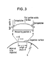
- the respective measuring positions are represented in terms of horizontal coordinate x (See Fig. 3), and representing a radius of a circular member to be inspected by R and a length of the chord formed as an inspection surface by l , the horizontal coordinate x can be transformed into a depth d from a surface by the following formula: Then, the half-width ratio H/Ho can be plotted as a function of the depth d . This is shown in Fig. 4.
- the relation between the depth d o and the amount of fatigue defect D is separately measured by means of a test piece, and the amount of fatigue defect D is determined on a diagram of the depth d o versus the amount of fatigue defect D.
- the diffraction apparatus is composed of an X-ray tube 1, a slit 2 and a detector 3, and these component parts are disposed on a movable base plate 4 that is common to an inspection surface forming apparatus (Fig. 6).
- a detection signal issued from the detector 3 is sent through a data pick-up and control section 5 to a computer 6, and control signals issued from the computer 6 are transmitted via the data pick-up and control section 5 to a drive section for the movable base plate 4 and the detector 3.
- the apparatus operates as follows:
Landscapes
- Chemical & Material Sciences (AREA)
- Biochemistry (AREA)
- Physics & Mathematics (AREA)
- Health & Medical Sciences (AREA)
- Life Sciences & Earth Sciences (AREA)
- Analytical Chemistry (AREA)
- Crystallography & Structural Chemistry (AREA)
- General Health & Medical Sciences (AREA)
- General Physics & Mathematics (AREA)
- Immunology (AREA)
- Pathology (AREA)
- Analysing Materials By The Use Of Radiation (AREA)
- Length-Measuring Devices Using Wave Or Particle Radiation (AREA)
Description
- The present invention relates to improvements in a method for evaluating a residual fatigue life of mechanical parts.
- Heretofore, in a process of maintenance and control for mechanical parts a defect hunting inspection was carried out, but according to this inspection it was only possible to determine whether the parts have reached their life or not. As methods for estimating about when cracks will be generated from a result of an inspection conducted prior to generation of cracks, a method of detecting changes in the nature of material which arise prior to generation of cracks and a method of observing micro cracks can be conceived, but either one of the methods is poor in precision, and there was almost no example of success as a practical method.
- US-A-4 287 416 discloses a method for evaluating a residual fatigue life of mechanical parts. In this method the half-width X-ray diffraction intensity data of a sample surface are collected and compared to the half-width data of an unfatigued material.
- However, according to this known method, the surface of the mechanical part to be inspected is not ground off. Further, the half-width values are detected by different X-ray tubes and compared to each other.
- This method is suitable to mechanical parts which are surface-hardened. The different X-ray tubes provide X-rays which are capable to intrude into the material to be inspected to different extents.
- As a representative one of the method for detecting changes in the nature of material, there is a method of making use of the X-ray diffraction process and paying attention to changes in a profile of the diffracted X-rays. Now description will be made on outline of this method with reference to Fig. 7.
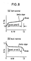
- Fig. 7 is a schematic diagram showing a general X-ray diffraction intensity curve, and a half-width indicated in this figure means a width of a peak at a 1/2 height of the peak in a profile of the diffracted X-rays. Representing the half-width by H and that before use by Ho, then as shown, for example, in Fig. 8, a half-width ratio H/Ho at the surface of a test sample has good correlation to a fatigue defect ratio N/Nf (N: number of repetitions of stress, Nf: number of repetitions of stress at breakdown). Accordingly, a degree of fatigue defect can be estimated from a half-width ratio.
- However, in the case of the first-mentioned method relying upon defect hunting, a precision is poor and the method is not practically available. Second, in the case of estimating a degree of fatigue defect from a profile of diffracted X-rays, since a gradient of change of a half-width ratio H/Ho with respect to a fatigue defect ratio N/Nf in the second period II which occupies most of a fatigue life is small as shown in Fig. 8, a precision in prediction of a life is poor. More particularly, with reference to Fig. 8, although change of nature of material occurs remarkably in the first period I, in the second period II change of nature of material at the surface is relatively stablized, then the energy accumulated by repeated stress is consumed rather by irreversible and microscopic deformation at the surface layer, resulting in nuclei of cracks and the nuclei breeds. The third period III involves the process of generation and propagation of cracks, and this period is outside of the object of a life. Taking into consideration these mechanisms leading to generation of fatigue cracks, with the half-width measuring method of the surface making use of the X-ray diffraction process, improvements in a precision of prediction of a life cannot be achieved.
- It is therefore one object of the present invention to provide an improved method for evaluating a residual fatigue life of mechanical parts making use of the X-ray diffraction process which is free from the shortcomings of a similar method in the prior art.
- A more specific object of the present invention is to provide a method for evaluating a residual fatigue life of mechanical parts, which has a high precision even in the second period of a fatigue life.
- According to one feature of the present invention, there is provided a method for evaluating a residual fatigue life of mechanical parts, consisting of the steps as claimed in the independent claim.
- In the second period II, while changes of nature of material are relatively stabilized on the surface, the changes of nature of material proceed towards the interior of the material during this second period II, and therefore, according to the present invention, since a depth of a surface layer in which changes of nature of material have occurred is measured and used as a parameter for evaluating the residual fatigue life, a precision of evaluation of the residual fatigue life can be enhanced.
- In the above-featured method for evaluating a residual fatigue life of mechanical parts according to the present invention, the initial value Ho of the half-width H is not known in general inspections, and so, a half-width value measured at a location where a loaded stress is small and the material is almost not subjected to fatigue defect, is substituted therefor. However, in a mechanical structure, since the nature of material is already not uniform at the time of manufacture, and so, in practice a location where the material is not subjected to fatigue defect, which location is as close as possible to the location where fatigue is to be detected, is sought, and the most probable initial value Hwo obtained by measuring a half-width value H at that location is substituted for the initial value Ho.
- From a change of profiles of diffracted X-rays at the successive points on an inspection surface that was ground by a minute amount, data as shown in Fig. 3 are obtained. Representing a depth from a surface at the successive measuring positions x by d, geometrically it can be calculated from the following equation:

Therefore, if a half-width ratio H/Ho is plotted as a function of the depth d, then a graph shown in Fig. 4 is obtained. - From a cross-point between two straight lines in Fig. 4, a depth d o of a defective region can be determined. Hence, on the basis of data correlating the depth d o with an amount of fatigue defect D that were separately obtained with respect to a test piece, the amount of fatigue defect can be determined from the depth d o (See Fig. 5).
- In the accompanying drawings:
- Fig. 1 is a schematic illustration of an X-ray diffraction system to be used for practicing the method for evaluating a residual fatigue life of mechanical parts according to the present invention;
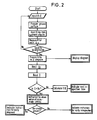
- Fig. 2 is a flow chart of a computer used in the system shown in Fig. 1;
- Fig. 3 is a diagrammatic representation of data picked up;
- Fig. 4 is a diagram prepared by rearranging the data in Fig. 3 into the form of a half-width ratio (H/Ho) versus a depth (d) from a surface;
- Fig. 5 is a diagram of a depth (do) of a defective region versus an amount of fatigue defect (D);
- Fig. 6 is a schematic view of an apparatus for forming an inspection surface;
- Fig. 7 is a diagram to be used for explaining a half-width of an X-ray diffraction curve; and
- Fig. 8 shows determination curves in the prior art used for estimating a degree of defect from changes of a half-width at the location to be detected.
- Now one preferred embodiment of the present invention will be explained with reference to Figs. 1 through 7.
- An inspection surface is formed by grinding a surface layer of a mechanical part to be inspected by a minute amount. For this formation of an inspection surface, for example, the means disclosed in copending Japanese Patent Application No. 60-53796 (see Fig. 6) could be employed.
- From a diagram of an X-ray diffraction intensity curve on the above-referred inspection surface (See Fig. 7), data (a half-width H versus a measuring position x) as shown in Fig. 3 are picked up. In Fig. 3, in the case where a flat portion appears at the position corresponding to the center of a chord formed by grinding a member, the half-width H at the flat portion is employed as a half-width Ho of unused material, half-width lines are extrapolated at the opposite end positions of the chord to obtain a half-width H at a fatigue defect portion. The half-width Ho obtained at the flat portion is the most probable original half-width Hwo. Upon picking up these data, for example, the means disclosed in copending Japanese Patent Application No. 60-53797 could be employed.
- The respective measuring positions are represented in terms of horizontal coordinate x (See Fig. 3), and representing a radius of a circular member to be inspected by R and a length of the chord formed as an inspection surface by ℓ, the horizontal coordinate x can be transformed into a depth d from a surface by the following formula:

Then, the half-width ratio H/Ho can be plotted as a function of the depth d. This is shown in Fig. 4. - These plotted data align on two intersecting straight lines. More particularly, at the positions of deep depth d, the data align on a flat horizontal line, and in a defective region where the depth d is smaller, the data points deviates linearly from the level of the flat straight line. Therefore, the cross-point between these two imaginary straight lines are sought by statistically analyzing the data, and from the horizontal coordinate of the cross-point, a depth d o of the defective region is determined.
- The relation between the depth d o and the amount of fatigue defect D is separately measured by means of a test piece, and the amount of fatigue defect D is determined on a diagram of the depth d o versus the amount of fatigue defect D.
- At a large amount of fatigue defect D, the possibility that microscopic cracks may be generated is large. Therefore, checking of the amount of fatigue defect D estimated by the method relying upon X-ray diffraction can be effected by carrying out observation of the inspection surface at the very surface in the proximity of the opposite ends of the prepared inspection surface. In addition, at the large amount of fatigue defect D, changes of the half-width ratio (H/Ho) [H represents a half-width at the surface obtained by extrapolation.] is large. Therefore, the confirmation can be done also through the method in the prior art illustrated in Fig. 8.
- It is to be noted that microscopic cracks are present within a very shallow surface layer. Therefore, although the observation of a practically operating mechanical part to which scale has adhered as a result of use was impossible, in the method of forming an inspection surface according to the above-referred copending Japanese Patent Application No. 60-53796, the surface layer is cut away obliquely so as to be exposed, and so, the observation becomes easy.
- Now, description will be made on an X-ray diffraction apparatus shown in Fig. 1. The diffraction apparatus is composed of an
X-ray tube 1, aslit 2 and adetector 3, and these component parts are disposed on amovable base plate 4 that is common to an inspection surface forming apparatus (Fig. 6). A detection signal issued from thedetector 3 is sent through a data pick-up andcontrol section 5 to acomputer 6, and control signals issued from thecomputer 6 are transmitted via the data pick-up andcontrol section 5 to a drive section for themovable base plate 4 and thedetector 3. The apparatus operates as follows: - (1) Under control of the
computer 6, each time the X-ray diffraction apparatus has picked up an X-ray diffraction curve for a given position at a distance x, themovable base plate 4 is automatically advanced in a stepwise manner. Each time, the distance x and the corresponding half-width H of the X-ray diffraction curve are calculated and recorded. - (2) A diagram of the half-width ratio H/Ho versus the depth d is produced by the
computer 6, and then it is determined whether or not a highly probable original half-width Ho has been obtained. If the probability is not sufficient, the inspection surface is ground again to obtain a larger cross-section chord length ℓ. - (3) Then, the depth d o of the defective region is read out from the diagram of H/Ho versus d.
- (4) On the basis of this value of the depth d o, the amount of fatigue defect D is determined. If the amount of fatigue defect D is large, an instruction for observation of microscopic cracks is issued.
- (5) As a result of the observation of microscopic cracks, if microscopic cracks are observed, an instruction is issued from the
computer 6 that any disposal should be done early. - (6) If microscopic cracks are not present, an instruction is issued from the
computer 6 that reinspection should be carried out early. - (7) In the event that the amount of fatigue defect D is small, on the basis of the value obtained by subtraction of 1-D, the time when inspection should be carried out next, is determined.
- The operation steps (1) to (7) above are programmed as a software in the
computer 6. That is, the operation of thecomputer 6 is represented in a flow chart as shown in Fig. 2. - Since the present invention is characterized by the above-described features, the following advantages can be obtained.
- (1) Owing to the fact that upon determining an amount of fatigue defect, a depth of a surface layer in which changes of nature of material have occurred is measured and it is used as a parameter for evaluating a residual life, a precision of evaluation of the residual life can be enhanced.
- (2) In addition, a precision of evaluation of the residual life can be enhanced by employing a half-width value measured at a location where the mechanical part to be inspected is not subjected to fatigue defect, which location is as close as possible to the location where fatigue is to be detected, as an initial half-width value Ho.
Claims (1)
- A method for evaluating a residual fatigue life of mechanical parts characterised by the steps of:- grinding off a surface layer of said mechanical part in an area that is to be exposed to X-rays, that has not been exposed to stress and thus can be employed as representing unused material;- measuring an X-ray intensity curve vs. the angle of diffraction for different positions (X) of said surface;- plotting the half-width value (H) of said curve against the corresponding measuring position (X), where in the plotted function has a linearly increasing part followed by a constant horizontal half-width value (Ho) which represents the half-width (Hwo) of the unused material;- transforming the measuring position (X) to a function of depth (d) of penetration according to the following equation:
 - deforming a normalized half-width function (H/Hwo) versus the depth d; and- determining the point do, where the linearly increasing part of the function meets the constant part of the intensity curve, which point (do) represents an indication of the fatigue defect (Δ).
Applications Claiming Priority (2)
| Application Number | Priority Date | Filing Date | Title |
|---|---|---|---|
| JP90025/86 | 1986-04-21 | ||
| JP61090025A JPH0621783B2 (en) | 1986-04-21 | 1986-04-21 | Fatigue / remaining life evaluation method for machine parts |
Publications (3)
| Publication Number | Publication Date |
|---|---|
| EP0242425A2 EP0242425A2 (en) | 1987-10-28 |
| EP0242425A3 EP0242425A3 (en) | 1989-04-19 |
| EP0242425B1 true EP0242425B1 (en) | 1992-08-12 |
Family
ID=13987141
Family Applications (1)
| Application Number | Title | Priority Date | Filing Date |
|---|---|---|---|
| EP86107348A Expired EP0242425B1 (en) | 1986-04-21 | 1986-05-30 | Method for evaluating residual fatigue life of mechanical parts |
Country Status (5)
| Country | Link |
|---|---|
| US (1) | US4709383A (en) |
| EP (1) | EP0242425B1 (en) |
| JP (1) | JPH0621783B2 (en) |
| CA (1) | CA1244151A (en) |
| DE (1) | DE3686414T2 (en) |
Cited By (1)
| Publication number | Priority date | Publication date | Assignee | Title |
|---|---|---|---|---|
| CN103901063A (en) * | 2014-04-23 | 2014-07-02 | 哈尔滨工业大学 | Method for testing C-fiber reinforced resin based composite material by virtue of X-ray diffraction |
Families Citing this family (18)
| Publication number | Priority date | Publication date | Assignee | Title |
|---|---|---|---|---|
| US4952804A (en) * | 1989-01-11 | 1990-08-28 | Electric Power Research Institute, Inc. | Electron diffraction method of determining the degree of fatigue for metallic materials |
| US5272746A (en) * | 1992-02-05 | 1993-12-21 | Genshi Nenryo Kogyo Kabushiki Kaisha | Method of evaluating a degree of fatigue in a structural material |
| US5490195A (en) * | 1994-05-18 | 1996-02-06 | Fatigue Management Associates Llc | Method for measuring and extending the service life of fatigue-limited metal components |
| US5737385A (en) * | 1996-07-02 | 1998-04-07 | Lambda Research, Inc. | Automated system for use in the determination of subsurface material properties by X-ray diffraction |
| GB9820918D0 (en) | 1998-09-26 | 1998-11-18 | Rolls Royce Plc | A method of determining if an alloy article has any remaining working life |
| US6415044B1 (en) | 1998-12-29 | 2002-07-02 | Advanced Material Processing | Non-destructive inspection method for an impact treated surface |
| CA2386135C (en) * | 1999-10-01 | 2010-01-26 | General Electric Railcar Services Corporation | Method and arrangement for inspection and requalification of lined vehicles used for transporting commodities and/or hazardous materials |
| US6634236B2 (en) * | 2000-08-31 | 2003-10-21 | Cooper Technology Services, Llc | Method and article of manufacture for estimating material failure due to crack formation and growth |
| RU2215280C1 (en) * | 2002-05-21 | 2003-10-27 | Котелкин Александр Викторович | Procedure evaluating residual service life of parts |
| EP2570790B1 (en) * | 2004-08-10 | 2015-11-04 | Dage precision Industries Ltd. | Shear test method |
| US7387030B1 (en) * | 2006-03-17 | 2008-06-17 | Florida Turbine Technologies, Inc. | Process for determining a remaining life for a gas turbine airfoil |
| EP2223089A1 (en) * | 2007-12-14 | 2010-09-01 | Ab Skf | Method of determining fatigue life and remaining life |
| US7735350B2 (en) * | 2008-09-29 | 2010-06-15 | General Electric Co. | Measuring intensity of shot peening in areas with difficult accessibility |
| DE102011079382B4 (en) * | 2011-07-19 | 2020-11-12 | Carl Zeiss Smt Gmbh | Method and device for analyzing and eliminating a defect in an EUV mask |
| CN102507400B (en) * | 2011-11-02 | 2014-04-30 | 嘉兴市特种设备检测院 | Quantitative analysis method for residual life of T91 steel pipes |
| JP5958999B2 (en) * | 2012-07-04 | 2016-08-02 | Ntn株式会社 | Bearing part inspection method and bearing part inspection apparatus |
| JP6984116B2 (en) * | 2016-10-27 | 2021-12-17 | 株式会社ジェイテクト | How to obtain the amount of polishing of metal parts |
| CN114018698B (en) * | 2021-10-20 | 2024-03-15 | 北京卫星制造厂有限公司 | Method for measuring and calculating intrinsic strength of composite material by using controllable processing damage |
Family Cites Families (4)
| Publication number | Priority date | Publication date | Assignee | Title |
|---|---|---|---|---|
| JPS5687849A (en) * | 1979-12-19 | 1981-07-16 | Hitachi Ltd | Foreknowing method for remaining life by x-rays |
| US4287416A (en) * | 1980-03-28 | 1981-09-01 | The United States Of America As Represented By The Secretary Of The Navy | Method of determining fatigue and stress corrosion damage |
| JPS56162039A (en) * | 1980-05-16 | 1981-12-12 | Hitachi Ltd | Method for foreseeing fatigue life of metallic material |
| JPS5744841A (en) * | 1980-09-01 | 1982-03-13 | Hitachi Ltd | Method and apparatus for x-ray diffraction |
-
1986
- 1986-04-21 JP JP61090025A patent/JPH0621783B2/en not_active Expired - Lifetime
- 1986-05-30 CA CA000510501A patent/CA1244151A/en not_active Expired
- 1986-05-30 US US06/868,744 patent/US4709383A/en not_active Expired - Fee Related
- 1986-05-30 EP EP86107348A patent/EP0242425B1/en not_active Expired
- 1986-05-30 DE DE8686107348T patent/DE3686414T2/en not_active Expired - Fee Related
Cited By (1)
| Publication number | Priority date | Publication date | Assignee | Title |
|---|---|---|---|---|
| CN103901063A (en) * | 2014-04-23 | 2014-07-02 | 哈尔滨工业大学 | Method for testing C-fiber reinforced resin based composite material by virtue of X-ray diffraction |
Also Published As
| Publication number | Publication date |
|---|---|
| US4709383A (en) | 1987-11-24 |
| JPS62247236A (en) | 1987-10-28 |
| JPH0621783B2 (en) | 1994-03-23 |
| CA1244151A (en) | 1988-11-01 |
| EP0242425A2 (en) | 1987-10-28 |
| DE3686414D1 (en) | 1992-09-17 |
| DE3686414T2 (en) | 1993-04-15 |
| EP0242425A3 (en) | 1989-04-19 |
Similar Documents
| Publication | Publication Date | Title |
|---|---|---|
| EP0242425B1 (en) | Method for evaluating residual fatigue life of mechanical parts | |
| US5748003A (en) | Microwaves used for determining fatigue and surface crack features on metal surfaces | |
| US6789428B2 (en) | Method and apparatus for evaluating damage of metal material | |
| US3981184A (en) | Ultrasonic diagnostic inspection systems | |
| US4870669A (en) | Gamma ray flaw detection system | |
| US4577337A (en) | X-Ray fluorescence testing of laminate structures | |
| CA1236591A (en) | Method and apparatus for crack detection and characterization | |
| CN111896629A (en) | A Rapid Detection Method for Surface Diseases of Tunnel Structures | |
| JP3848641B2 (en) | Concrete inspection method using electromagnetic waves and concrete inspection apparatus using electromagnetic waves | |
| EP0075997A2 (en) | Well logging device | |
| CA1098221A (en) | Gamma ray calibration system | |
| JP3091856B2 (en) | How to evaluate the fatigue of structural materials | |
| Jax et al. | Acoustic emission inspections of nuclear components considering recent research programmes | |
| JPH05180776A (en) | Probing system for excavation surface | |
| EP0407930A1 (en) | Nondestructive inspection method and apparatus | |
| CN121298907B (en) | Bolt monitoring method and device based on electromagnetic ultrasonic and 3D phased array | |
| KR102800017B1 (en) | System for measuring concrete carbonation using raman spectroscopy, and method for the same | |
| JP3531019B2 (en) | Defect identification method by ultrasonic flaw detection | |
| GB2169102A (en) | Non-destructive testing | |
| JP7756592B2 (en) | Ultrasonic inspection method and ultrasonic inspection device | |
| JP7455046B2 (en) | Underwater inspection equipment and underwater inspection method | |
| US4172315A (en) | Method of manufacturing a magnetic field sensitivity indicator apparatus for evaluating magnetic fields in parts during magnetic particle inspection | |
| JPH07117531B2 (en) | Method for evaluating remaining life of heat-resistant steel | |
| Pitkaenen et al. | NDT reliability in risk minimization during manufacturing and welding of spent nuclear fuel disposal components-A realistic tool for reliable inspections | |
| Hull et al. | Other Non-destructive Inspection Techniques |
Legal Events
| Date | Code | Title | Description |
|---|---|---|---|
| PUAI | Public reference made under article 153(3) epc to a published international application that has entered the european phase |
Free format text: ORIGINAL CODE: 0009012 |
|
| 17P | Request for examination filed |
Effective date: 19860627 |
|
| AK | Designated contracting states |
Kind code of ref document: A2 Designated state(s): CH DE GB LI |
|
| PUAL | Search report despatched |
Free format text: ORIGINAL CODE: 0009013 |
|
| AK | Designated contracting states |
Kind code of ref document: A3 Designated state(s): CH DE GB LI |
|
| 17Q | First examination report despatched |
Effective date: 19901001 |
|
| GRAA | (expected) grant |
Free format text: ORIGINAL CODE: 0009210 |
|
| AK | Designated contracting states |
Kind code of ref document: B1 Designated state(s): CH DE GB LI |
|
| REF | Corresponds to: |
Ref document number: 3686414 Country of ref document: DE Date of ref document: 19920917 |
|
| PLBE | No opposition filed within time limit |
Free format text: ORIGINAL CODE: 0009261 |
|
| STAA | Information on the status of an ep patent application or granted ep patent |
Free format text: STATUS: NO OPPOSITION FILED WITHIN TIME LIMIT |
|
| 26N | No opposition filed | ||
| PGFP | Annual fee paid to national office [announced via postgrant information from national office to epo] |
Ref country code: DE Payment date: 19950523 Year of fee payment: 10 |
|
| PGFP | Annual fee paid to national office [announced via postgrant information from national office to epo] |
Ref country code: CH Payment date: 19950524 Year of fee payment: 10 |
|
| PGFP | Annual fee paid to national office [announced via postgrant information from national office to epo] |
Ref country code: GB Payment date: 19960521 Year of fee payment: 11 |
|
| PG25 | Lapsed in a contracting state [announced via postgrant information from national office to epo] |
Ref country code: LI Effective date: 19960531 Ref country code: CH Effective date: 19960531 |
|
| REG | Reference to a national code |
Ref country code: CH Ref legal event code: PL |
|
| PG25 | Lapsed in a contracting state [announced via postgrant information from national office to epo] |
Ref country code: DE Effective date: 19970201 |
|
| PG25 | Lapsed in a contracting state [announced via postgrant information from national office to epo] |
Ref country code: GB Effective date: 19970530 |
|
| GBPC | Gb: european patent ceased through non-payment of renewal fee |
Effective date: 19970530 |