EP0242345B1 - Gleitstützelement für eine Durchbiegungseinstellwalze - Google Patents
Gleitstützelement für eine Durchbiegungseinstellwalze Download PDFInfo
- Publication number
- EP0242345B1 EP0242345B1 EP87850111A EP87850111A EP0242345B1 EP 0242345 B1 EP0242345 B1 EP 0242345B1 EP 87850111 A EP87850111 A EP 87850111A EP 87850111 A EP87850111 A EP 87850111A EP 0242345 B1 EP0242345 B1 EP 0242345B1
- Authority
- EP
- European Patent Office
- Prior art keywords
- glide
- projection part
- shoe
- pistons
- shoes
- Prior art date
- Legal status (The legal status is an assumption and is not a legal conclusion. Google has not performed a legal analysis and makes no representation as to the accuracy of the status listed.)
- Expired - Lifetime
Links
Images

Classifications
-
- F—MECHANICAL ENGINEERING; LIGHTING; HEATING; WEAPONS; BLASTING
- F16—ENGINEERING ELEMENTS AND UNITS; GENERAL MEASURES FOR PRODUCING AND MAINTAINING EFFECTIVE FUNCTIONING OF MACHINES OR INSTALLATIONS; THERMAL INSULATION IN GENERAL
- F16C—SHAFTS; FLEXIBLE SHAFTS; ELEMENTS OR CRANKSHAFT MECHANISMS; ROTARY BODIES OTHER THAN GEARING ELEMENTS; BEARINGS
- F16C13/00—Rolls, drums, discs, or the like; Bearings or mountings therefor
- F16C13/02—Bearings
- F16C13/022—Bearings supporting a hollow roll mantle rotating with respect to a yoke or axle
- F16C13/024—Bearings supporting a hollow roll mantle rotating with respect to a yoke or axle adjustable for positioning, e.g. radial movable bearings for controlling the deflection along the length of the roll mantle
- F16C13/026—Bearings supporting a hollow roll mantle rotating with respect to a yoke or axle adjustable for positioning, e.g. radial movable bearings for controlling the deflection along the length of the roll mantle by fluid pressure
- F16C13/028—Bearings supporting a hollow roll mantle rotating with respect to a yoke or axle adjustable for positioning, e.g. radial movable bearings for controlling the deflection along the length of the roll mantle by fluid pressure with a plurality of supports along the length of the roll mantle, e.g. hydraulic jacks
-
- D—TEXTILES; PAPER
- D21—PAPER-MAKING; PRODUCTION OF CELLULOSE
- D21G—CALENDERS; ACCESSORIES FOR PAPER-MAKING MACHINES
- D21G1/00—Calenders; Smoothing apparatus
- D21G1/02—Rolls; Their bearings
- D21G1/0206—Controlled deflection rolls
- D21G1/0213—Controlled deflection rolls with deflection compensation means acting between the roller shell and its supporting member
- D21G1/022—Controlled deflection rolls with deflection compensation means acting between the roller shell and its supporting member the means using fluid pressure
Definitions
- the present invention concerns a glide-shoe arrangement for a variable-crown roll, comprising a non-revolving massive central axle, on which a cylindrical roll mantle is revolvingly journalled, between which axle and the inside face of said roll mantle piston-glide-shoe combinations loaded by means of hydraulic pressure fluid are fitted, whose glide shoes can be loaded by the intermediary of pistons by means of the pressures of the hydraulic fluid against the inside face of the roll mantle for the purpose of controlling the distribution of the nip pressure in a nip placed facing said loading shoes, said piston-glide-shoe combinations including cylindrical or equivalent bores formed in said axle, into which bores cylindrical or equivalent pistons are fitted, and between which loading pistons and their glide shoes bearings are fitted which are provided with spherical bearing faces, the center of rotation of said bearings being arranged at the glide shoe side of the piston-glide-shoe combinations.
- variable-crown or adjustable-crown rolls for paper machines are known.
- these rolls comprise a massive, stationary roll axle and a roll mantle arranged as revolving around the said axle. Between the said axle and the mantle, a series of glide shoes and/or chambers of pressure fluid, acting upon the inner face of the mantle, are fitted.
- the nips formed by such rolls such as press nips or calendering nips, are loaded by means of loading forces applied to the axle journals of the variable-crown roll and of its counter-roll.
- variable-crown or adjustable-crown rolls as include a series of glide shoes whose glide faces act upon the inner face of the roll mantle and whose glide faces are at least partly hydrostatically lubricated by means of pressure fluid passed onto the glide face.
- the invention is mainly characterized in that a pin-shaped projection part is fitted in said loading pistons, which projection part extends through said bearing, and which pin-shaped projection part is mainly a cylindrical body whose centre axis substantially coincides with the centre axis of the cylindrical bores for the pistons; that between said pin-shaped projection part and the glide shoe or a projection part attached to the glide shoe, there is a sealed articulation arrangement which is placed substantially in the same plane in which the center of rotation of said bearing that has spherical bearing faces is placed; and that - the pressure fluid can be passed from the loading space of the pistons through said pin-shaped projection part into hydrostatic lubrication spaces on the glide shoes.
- the centres of rotation of the glide shoes become placed near the inner face of the roll mantle, i.e. near the glide face of the glide shoes, whereby the friction between the roll mantle and the glide shoes causes a minimum of a moment inclining the shoes.
- the seal ring between the pin of the loading piston and the glide shoe or a component attached to the glide shoe is placed in the plane of the centre of rotation of the glide shoes, the seal moves in operation as little as possible, and thereby it can be sealed reliably and its construction can be made simple.
- roller comprising an articulated joint floating by the aid of an intermediate chamber.
- a simpler, non-floating articulated joint can be used according to the invention owing to the pin-shaped projection part fitted in the loading pistons.
- a spherical bearing having a very small radius.
- the corresponding radius in the arrangement shown in the GB document is larger by at least one order of magnitude. Moreover, the sealing in the area of the pressure reduction chamber shown in whould cause great difficulties.
- US-A 3 782 793 shows a bearing construction with an articulated joint floating by the aid of an intermediate chamber.
- the joint point of the piston is not in the center of rotation of the bearing surface, and consequently the structure does not enable the piston to incline to a sufficiently great degree.
- the structure of the invention enables the piston to incline to a sufficient degree with respect to the deflection of the axle.
- the roll 10 e.g. a press roll or calender roll for a paper machine, comprises a revolving cylinder mantle 11, within which there is a stationary massive axle 12. Between the inner face 11' of the mantle 11 and the axle 12 a sufficiently large free space 13 remains.
- the mantle 11 is journalled on axle journals 12a and 12b, which constitute extensions of the axle 12, by means of bearings 13a and 13b.
- the mantle 11 is closed by end flanges 14a and 14b.
- the roll mantle 11 is driven by the intermediate of a drive mechanism not shown.
- another roll 50 Opposite the roll 10, another roll 50 is provided, which said rolls 10 and 50 together form, e.g., a press nip N.
- a piston-loading-shoe combination 20i...20 N in accordance with the invention is provided, by whose means the linear load in the nip N can be adjusted in zones and compensated to the desired level, e.g. so as to make a uniformly distributed linear load.
- each of the said cylinders 16 a separately adjustable pressure of appropriate magnitude is passed from an external pressure source (not shown) through fluid ducts.
- an external pressure source not shown
- each piston 15 of, e.g., circular section.
- a loading shoe 22 of its own is connected to each piston 15 .
- the loading shoes 22 are identical with each other, and they are spaced axially as densely as possible so that a uniform load is provided on the cylinder mantle 11 even with high compensation forces.
- the shoes 22 include, e.g., two hydrostatic lubrication chambers 23a and 23b, between which and at whose edges there are ridges 24, which form a lubricated glide face against the smooth inner face 11' of the mantle 11.
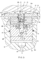
- lubrication oil has been passed out of the pressure space 16p in the piston 15 through the bore 26 in the piston 15 as well as through a support joint arrangement 30 in accordance with the present invention, which will be described in more detail below.
- the support joint arrangement 30 in accordance with the invention placed between the glide shoes 22 and the loading pistons 15, operates as a pressure-tight fitting, by means of which the pressurized fluid is passed from the pressure spaces 16p in the cylinders 16 of the loading pistons 15 into the lubrication chambers 23a and 23b on the glide shoes 22.
- a projection piece 36 is attached, which is placed with a sufficiently wide play inside the cylinder bores 16.
- a bearing piece 32 is fixed.
- a second bearing piece 31 is fixed to a bore 21 in the end face of the piston 15.
- the bearing pieces 31 and 32 have spherical bearing faces 33 facing each other, whose journalling centre is, in Fig. 3, denoted with 0, and the journalling radius with R.
- the pistons 15 have a central bore 26, to whose wider part a pin 25 is fixed, which extends centrally through the bearing 31,32,33 into a central bore 38 in the projection piece 36 of the glide shoe 22.
- a pin 25 In the part of the said pin 25 that is placed inside the projection piece 36, there are two ring flanges 28, an elastic seal ring 39, e.g. of rubber, being fitted in a groove 29 between the said flanges.
- a bore 27 passes through the pin 25, one end of the said bore being connected with the bore 26 in the piston 15, and the other end with the space 40 in the projection piece 36 of the glide shoe 22.
- the bores 22p in the glide shoe 22 open into the said space 40.
- the pressure fluid is passed along the route 26-27-40-22p into the spaces 23a and 23b on the glide shoes 22 so as to lubricate the glide face between the glide shoes 22 and the inner face 11' of the roll mantle 11 hydrostatically.
- the route of the said pressure fluid is sealed at the joint of the combination 30 by the ring seal 39 of the pin 25 against the inner face of the bore 38 in the projection part 36.
- the centre of rotation 0 of the spherical bearing 31,32,33 of the pistons 15 and of the glide shoe 22 is placed at the level of the seal 39 of the piston 15 pin 25 so that, when the glide shoe 22 and its fixed projection part 36 pivot relative the piston 15, the seal 39 moves very little relative the walls of the bores 38 in the projection part 36, and hereby a simple and reliable seal construction is obtained.
- the centres of rotation 0 of the pistons 15 and of the glide shoes 22 are placed as near the glide face between the glide shoe 22 and the mantle 11 as possible, out of the reasons mentioned above.
- the pistons 15 are sealed by seal rings 17.
- the joint arrangement 30 guarantees that, in spite of relative changes in position between the central axle 12 and the mantle 11, the glide contact of the glide shoe remains correct, and, moreover, the pistons 15 are not stuck in their bores 16.
- the glide-shoe arrangement in accordance with the invention is intended for use in connection with such glide shoes in which a partly, preferably mainly, hydrostatic lubrication is used.
- a partly hydrostatic lubrication is used in the glide shoes.
- partly hydrodynamic lubrication which is implied by the chamferings 41 at the edges of the glide faces on the glide shoes 22, which said chamferings, together with the inner face 11' of the mantle 11, define wedge spaces, in which a dam pressure of lubricant is produced, by means of which the glide face may, if necessary, also be lubricated partly hydrodynamically.
- the glide-shoe arrangement is shown with the correct proportions and in the scale 1:1.5.
- the length of the glide shoe in the direction of rotation of the roll mantle 11 is denoted with L, the diameter of the loading piston 15 with D, the radius of the spherical bearing with R, and the perpendicular distance of the journalling centre 0 of the said spherical bearing from the glide face of the mantle 11 with E.
- the construction described above operates mainly as follows.
- the axle 12 is pressed by the intermediate of articulated bearings (not shown) attached to its axle journals 12a and 12b against the counter-roll 50 so as to load the nip N, whereby the axle 12 is, at the same time, deflected.
- a fluid pressure of adjustable magnitude is applied through the ducts 18 so as to load the glide-shoe- piston combinations 20 1 ...20 N , which said pressure presses the pistons 15 and the shoes 22 attached to the pistons within the area of the nip N against the inner face 11' of the roll mantle 11.
- the shoes 22 receive their lubrication oil from the loading oil and pressure of the pistons 15, so that the pressure of the lubrication oil in the spaces 23a and 23b is proportional to the loading pressure of the pistons 15 and the shoes 22 attached to same.
- the shoes 22 are able to be positioned in accordance with the mantle 11 and the pistons 15 in accordance with the central axle, because the pistons 20 and the shoes 22 are interconnected by the support joint arrangement 30.
- the shoes 22 are also capable of being positioned in the cross-sectional plane of the roll 10 around the spherical joints 31,32,33, and this positioning is not interfered with by the sealed passage of the lubrication oil into the chambers 23a and 23b on the shoes 22.
Landscapes
- Physics & Mathematics (AREA)
- Fluid Mechanics (AREA)
- Engineering & Computer Science (AREA)
- General Engineering & Computer Science (AREA)
- Mechanical Engineering (AREA)
- Paper (AREA)
- Rolls And Other Rotary Bodies (AREA)
- Reduction Rolling/Reduction Stand/Operation Of Reduction Machine (AREA)
- Pivots And Pivotal Connections (AREA)
- Heterocyclic Carbon Compounds Containing A Hetero Ring Having Oxygen Or Sulfur (AREA)
- Wire Processing (AREA)
- Registering, Tensioning, Guiding Webs, And Rollers Therefor (AREA)
Claims (6)
Priority Applications (1)
| Application Number | Priority Date | Filing Date | Title |
|---|---|---|---|
| AT87850111T ATE50031T1 (de) | 1986-04-16 | 1987-04-07 | Gleitstuetzelement fuer eine durchbiegungseinstellwalze. |
Applications Claiming Priority (2)
| Application Number | Priority Date | Filing Date | Title |
|---|---|---|---|
| FI861612 | 1986-04-16 | ||
| FI861612A FI74072C (fi) | 1986-04-16 | 1986-04-16 | Glidskoarrangemang foer boejningskompenserad vals. |
Publications (3)
| Publication Number | Publication Date |
|---|---|
| EP0242345A2 EP0242345A2 (de) | 1987-10-21 |
| EP0242345A3 EP0242345A3 (en) | 1988-01-27 |
| EP0242345B1 true EP0242345B1 (de) | 1990-01-31 |
Family
ID=8522472
Family Applications (1)
| Application Number | Title | Priority Date | Filing Date |
|---|---|---|---|
| EP87850111A Expired - Lifetime EP0242345B1 (de) | 1986-04-16 | 1987-04-07 | Gleitstützelement für eine Durchbiegungseinstellwalze |
Country Status (8)
| Country | Link |
|---|---|
| US (1) | US4757586A (de) |
| EP (1) | EP0242345B1 (de) |
| JP (1) | JPH07107238B2 (de) |
| AT (1) | ATE50031T1 (de) |
| CA (1) | CA1306893C (de) |
| DE (1) | DE3761586D1 (de) |
| FI (1) | FI74072C (de) |
| SU (1) | SU1639436A3 (de) |
Cited By (1)
| Publication number | Priority date | Publication date | Assignee | Title |
|---|---|---|---|---|
| DE10239089A1 (de) * | 2002-08-26 | 2004-03-11 | Voith Paper Patent Gmbh | Biegeausgleichswalze |
Families Citing this family (5)
| Publication number | Priority date | Publication date | Assignee | Title |
|---|---|---|---|---|
| US5060357A (en) * | 1990-06-21 | 1991-10-29 | Beloit Corporation | Self-loading controlled deflection roll |
| DE9205796U1 (de) * | 1992-04-30 | 1993-08-26 | Eduard Küsters Maschinenfabrik GmbH & Co KG, 47805 Krefeld | Walze mit Stützleiste |
| DE4426513C2 (de) * | 1994-07-27 | 1997-07-17 | Voith Sulzer Papiermasch Gmbh | Durchbiegungseinstellwalze |
| DE19960872A1 (de) * | 1999-12-17 | 2001-07-05 | Valmet Corp | Walzenpaar zur Bildung eines Pressenlangspalts |
| CN105697558A (zh) * | 2016-04-01 | 2016-06-22 | 江苏鹏飞集团股份有限公司 | 一种自定位滑履轴承 |
Family Cites Families (18)
| Publication number | Priority date | Publication date | Assignee | Title |
|---|---|---|---|---|
| AU449519B2 (en) * | 1970-11-30 | 1974-05-30 | Advanced Products Pty Ltd | Journal support bearings for rotating shafts |
| DE2229421A1 (de) * | 1972-06-16 | 1974-01-03 | Bosch Gmbh Robert | Kolben-gleitschuh-element fuer hydrostatische kolbenmaschinen |
| CH567667A5 (de) | 1972-09-16 | 1975-10-15 | Escher Wyss Ag | |
| US3782793A (en) * | 1973-01-24 | 1974-01-01 | Hoesch Werke Ag | Bearing construction |
| CH576083A5 (de) * | 1974-02-12 | 1976-05-31 | Escher Wyss Ag | |
| GB1507987A (en) * | 1974-07-15 | 1978-04-19 | British Steel Corp | Mill stand roll parameter monitor |
| DE2502161A1 (de) * | 1975-01-21 | 1976-07-29 | Voith Gmbh J M | Presswalze fuer papiermaschinen zur erzeugung eines liniendruckes |
| US4064607A (en) * | 1975-01-21 | 1977-12-27 | J. M. Voith G.M.B.H. | Compression roller for paper producing machinery |
| CH615487A5 (de) | 1977-02-23 | 1980-01-31 | Escher Wyss Ag | |
| AT360831B (de) * | 1977-12-20 | 1981-02-10 | Escher Wyss Ag | Hydraulisches stuetzelement |
| DE2838427A1 (de) * | 1978-09-02 | 1980-03-06 | Voith Gmbh J M | Walze fuer die druckbehandlung von materialbahnen, insbesondere papierbahnen |
| DE2849253C2 (de) * | 1978-11-08 | 1981-01-08 | Escher Wyss Ag, Zuerich (Schweiz) | Durchbiegungseinstellwalze |
| DE2942002C2 (de) * | 1979-10-17 | 1982-06-16 | Kleinewefers Gmbh, 4150 Krefeld | Druckbehandlungswalze |
| DE3007112A1 (de) * | 1980-02-26 | 1981-09-03 | J.M. Voith Gmbh, 7920 Heidenheim | Stuetzvorrichtung fuer eine walze |
| DE3012732C2 (de) * | 1980-03-25 | 1986-05-07 | Sulzer-Escher Wyss AG, Zürich | Hydrostatisches Stützelement zur Abstützung eines gestützten Teiles auf einem stützenden Teil |
| DE3011669C2 (de) * | 1980-03-26 | 1982-11-25 | J.M. Voith Gmbh, 7920 Heidenheim | Preßwalze mit einer Einrichtung zum Korrigieren der Durchbiegung des Walzenmantels |
| DE3042616C2 (de) | 1980-11-12 | 1983-04-07 | Kleinewefers Gmbh, 4150 Krefeld | Druckbehandlungswalze mit hydraulischer Abstützung |
| DE3306838A1 (de) * | 1983-02-26 | 1984-08-30 | J.M. Voith Gmbh, 7920 Heidenheim | Presswalze, deren durchbiegung einstellbar ist |
-
1986
- 1986-04-16 FI FI861612A patent/FI74072C/fi not_active IP Right Cessation
-
1987
- 1987-04-06 JP JP62083135A patent/JPH07107238B2/ja not_active Expired - Lifetime
- 1987-04-07 DE DE8787850111T patent/DE3761586D1/de not_active Expired - Lifetime
- 1987-04-07 AT AT87850111T patent/ATE50031T1/de not_active IP Right Cessation
- 1987-04-07 EP EP87850111A patent/EP0242345B1/de not_active Expired - Lifetime
- 1987-04-14 US US07/038,222 patent/US4757586A/en not_active Expired - Lifetime
- 1987-04-15 SU SU874202306A patent/SU1639436A3/ru active
- 1987-04-15 CA CA000534792A patent/CA1306893C/en not_active Expired - Lifetime
Cited By (1)
| Publication number | Priority date | Publication date | Assignee | Title |
|---|---|---|---|---|
| DE10239089A1 (de) * | 2002-08-26 | 2004-03-11 | Voith Paper Patent Gmbh | Biegeausgleichswalze |
Also Published As
| Publication number | Publication date |
|---|---|
| EP0242345A2 (de) | 1987-10-21 |
| US4757586A (en) | 1988-07-19 |
| SU1639436A3 (ru) | 1991-03-30 |
| FI74072C (fi) | 1987-12-10 |
| FI74072B (fi) | 1987-08-31 |
| JPH07107238B2 (ja) | 1995-11-15 |
| FI861612A0 (fi) | 1986-04-16 |
| JPS62243898A (ja) | 1987-10-24 |
| ATE50031T1 (de) | 1990-02-15 |
| EP0242345A3 (en) | 1988-01-27 |
| DE3761586D1 (de) | 1990-03-08 |
| CA1306893C (en) | 1992-09-01 |
Similar Documents
| Publication | Publication Date | Title |
|---|---|---|
| CA1263551A (en) | Pressure roll for use in calenders or the like | |
| CA1219153A (en) | Hydrostatic support member, particularly for rolling mills | |
| EP0332594B1 (de) | Walze mit anpassbarer Biegelinie | |
| EP0241442A2 (de) | Verfahren zum Steuern der Durchbiegung einer Walze mit anpassbarer Biegelinie und Papiermaschinenwalze mit Anwendung des Verfahrens | |
| EP0373942B1 (de) | Stützvorrichtung für eine veränderliche Zylinderwalze | |
| EP0897484B1 (de) | Hydrostatisches lager für eine rolle oder dergleichen | |
| US4776069A (en) | Piston-glide shoe combination in a variable-crown roll | |
| CA1285806C (en) | Pressure roll for use in calenders and the like | |
| KR960702891A (ko) | 편향롤의 셸에 이용되는 조정 가능한 베어링(adjustable bearing for the shell of a deflection roll) | |
| EP0242345A2 (de) | Gleitstützelement für eine Durchbiegungseinstellwalze | |
| US4747195A (en) | Roll for use in a paper machine | |
| US5702337A (en) | Roll arrangement | |
| CA1307967C (en) | Press rolls | |
| EP0705938B1 (de) | Verfahren und Einrichtung zur seitlichen Abstützung eines Rollmantels | |
| US6346066B1 (en) | Tubular roll provided with hydraulically loaded glide bearings | |
| US4856155A (en) | Method and device in an adjustable-crown roll | |
| CA2271712C (en) | Pressure processing roll | |
| US3418703A (en) | Antideflection roll with non-rotating beam and lever supports | |
| WO1998036195A1 (en) | Axial seal for a revolving member, in particular for an axle, shaft or equivalent | |
| CA2249382C (en) | Hydrostatic glide bearing for a roll or equivalent | |
| FI81184C (fi) | Boejningskompenserad vals. |
Legal Events
| Date | Code | Title | Description |
|---|---|---|---|
| PUAI | Public reference made under article 153(3) epc to a published international application that has entered the european phase |
Free format text: ORIGINAL CODE: 0009012 |
|
| AK | Designated contracting states |
Kind code of ref document: A2 Designated state(s): AT DE FR GB SE |
|
| PUAL | Search report despatched |
Free format text: ORIGINAL CODE: 0009013 |
|
| AK | Designated contracting states |
Kind code of ref document: A3 Designated state(s): AT DE FR GB SE |
|
| 17P | Request for examination filed |
Effective date: 19880303 |
|
| 17Q | First examination report despatched |
Effective date: 19880706 |
|
| GRAA | (expected) grant |
Free format text: ORIGINAL CODE: 0009210 |
|
| AK | Designated contracting states |
Kind code of ref document: B1 Designated state(s): AT DE FR GB SE |
|
| REF | Corresponds to: |
Ref document number: 50031 Country of ref document: AT Date of ref document: 19900215 Kind code of ref document: T |
|
| REF | Corresponds to: |
Ref document number: 3761586 Country of ref document: DE Date of ref document: 19900308 |
|
| ET | Fr: translation filed | ||
| PLBI | Opposition filed |
Free format text: ORIGINAL CODE: 0009260 |
|
| 26 | Opposition filed |
Opponent name: KLEINEWEFERS GMBH Effective date: 19901027 |
|
| RAP2 | Party data changed (patent owner data changed or rights of a patent transferred) |
Owner name: VALMET PAPER MACHINERY INC. |
|
| PLBN | Opposition rejected |
Free format text: ORIGINAL CODE: 0009273 |
|
| STAA | Information on the status of an ep patent application or granted ep patent |
Free format text: STATUS: OPPOSITION REJECTED |
|
| 27O | Opposition rejected |
Effective date: 19930921 |
|
| EAL | Se: european patent in force in sweden |
Ref document number: 87850111.3 |
|
| PGFP | Annual fee paid to national office [announced via postgrant information from national office to epo] |
Ref country code: AT Payment date: 19990324 Year of fee payment: 13 |
|
| PGFP | Annual fee paid to national office [announced via postgrant information from national office to epo] |
Ref country code: FR Payment date: 19990325 Year of fee payment: 13 |
|
| PGFP | Annual fee paid to national office [announced via postgrant information from national office to epo] |
Ref country code: GB Payment date: 19990408 Year of fee payment: 13 |
|
| PGFP | Annual fee paid to national office [announced via postgrant information from national office to epo] |
Ref country code: SE Payment date: 19990414 Year of fee payment: 13 |
|
| PG25 | Lapsed in a contracting state [announced via postgrant information from national office to epo] |
Ref country code: GB Free format text: LAPSE BECAUSE OF NON-PAYMENT OF DUE FEES Effective date: 20000407 Ref country code: AT Free format text: LAPSE BECAUSE OF NON-PAYMENT OF DUE FEES Effective date: 20000407 |
|
| PG25 | Lapsed in a contracting state [announced via postgrant information from national office to epo] |
Ref country code: SE Free format text: LAPSE BECAUSE OF NON-PAYMENT OF DUE FEES Effective date: 20000408 |
|
| GBPC | Gb: european patent ceased through non-payment of renewal fee |
Effective date: 20000407 |
|
| EUG | Se: european patent has lapsed |
Ref document number: 87850111.3 |
|
| PG25 | Lapsed in a contracting state [announced via postgrant information from national office to epo] |
Ref country code: FR Free format text: LAPSE BECAUSE OF NON-PAYMENT OF DUE FEES Effective date: 20001229 |
|
| REG | Reference to a national code |
Ref country code: FR Ref legal event code: ST |
|
| PGFP | Annual fee paid to national office [announced via postgrant information from national office to epo] |
Ref country code: DE Payment date: 20010411 Year of fee payment: 15 |
|
| PG25 | Lapsed in a contracting state [announced via postgrant information from national office to epo] |
Ref country code: DE Free format text: LAPSE BECAUSE OF NON-PAYMENT OF DUE FEES Effective date: 20021101 |
|
| APAH | Appeal reference modified |
Free format text: ORIGINAL CODE: EPIDOSCREFNO |