EP0242218B1 - Coal-water slurry producing system - Google Patents
Coal-water slurry producing system Download PDFInfo
- Publication number
- EP0242218B1 EP0242218B1 EP87303371A EP87303371A EP0242218B1 EP 0242218 B1 EP0242218 B1 EP 0242218B1 EP 87303371 A EP87303371 A EP 87303371A EP 87303371 A EP87303371 A EP 87303371A EP 0242218 B1 EP0242218 B1 EP 0242218B1
- Authority
- EP
- European Patent Office
- Prior art keywords
- coal
- mill
- slurry
- particles
- screen
- Prior art date
- Legal status (The legal status is an assumption and is not a legal conclusion. Google has not performed a legal analysis and makes no representation as to the accuracy of the status listed.)
- Expired
Links
- 239000002002 slurry Substances 0.000 title claims description 85
- XLYOFNOQVPJJNP-UHFFFAOYSA-N water Substances O XLYOFNOQVPJJNP-UHFFFAOYSA-N 0.000 title claims description 48
- 239000002245 particle Substances 0.000 claims description 62
- 239000003245 coal Substances 0.000 claims description 55
- 238000000227 grinding Methods 0.000 claims description 18
- 238000011084 recovery Methods 0.000 claims description 18
- 239000000463 material Substances 0.000 claims description 9
- 239000002184 metal Substances 0.000 claims description 9
- 239000007788 liquid Substances 0.000 claims description 4
- 239000011362 coarse particle Substances 0.000 claims description 3
- 238000001914 filtration Methods 0.000 claims description 3
- 239000000203 mixture Substances 0.000 claims description 2
- 238000007599 discharging Methods 0.000 claims 1
- 238000011049 filling Methods 0.000 description 25
- 239000000654 additive Substances 0.000 description 4
- 238000002474 experimental method Methods 0.000 description 4
- 239000000047 product Substances 0.000 description 4
- 238000005265 energy consumption Methods 0.000 description 3
- 238000012545 processing Methods 0.000 description 3
- 238000003860 storage Methods 0.000 description 3
- 239000004094 surface-active agent Substances 0.000 description 3
- 238000000498 ball milling Methods 0.000 description 2
- 238000002485 combustion reaction Methods 0.000 description 2
- 239000000446 fuel Substances 0.000 description 2
- 238000010327 methods by industry Methods 0.000 description 2
- 238000005549 size reduction Methods 0.000 description 2
- 239000011335 coal coke Substances 0.000 description 1
- 238000013461 design Methods 0.000 description 1
- 238000010586 diagram Methods 0.000 description 1
- 230000000694 effects Effects 0.000 description 1
- 239000012467 final product Substances 0.000 description 1
- 230000005484 gravity Effects 0.000 description 1
- 229910052500 inorganic mineral Inorganic materials 0.000 description 1
- 238000000034 method Methods 0.000 description 1
- 238000003801 milling Methods 0.000 description 1
- 239000011707 mineral Substances 0.000 description 1
- 238000002156 mixing Methods 0.000 description 1
- 239000003002 pH adjusting agent Substances 0.000 description 1
- 238000005192 partition Methods 0.000 description 1
- 239000002006 petroleum coke Substances 0.000 description 1
- 238000005086 pumping Methods 0.000 description 1
- 239000002994 raw material Substances 0.000 description 1
- 238000012958 reprocessing Methods 0.000 description 1
- 238000011160 research Methods 0.000 description 1
- 238000000926 separation method Methods 0.000 description 1
- 239000007787 solid Substances 0.000 description 1
- 239000004449 solid propellant Substances 0.000 description 1
- 238000012360 testing method Methods 0.000 description 1
- 238000011144 upstream manufacturing Methods 0.000 description 1
Images


Classifications
-
- B—PERFORMING OPERATIONS; TRANSPORTING
- B02—CRUSHING, PULVERISING, OR DISINTEGRATING; PREPARATORY TREATMENT OF GRAIN FOR MILLING
- B02C—CRUSHING, PULVERISING, OR DISINTEGRATING IN GENERAL; MILLING GRAIN
- B02C23/00—Auxiliary methods or auxiliary devices or accessories specially adapted for crushing or disintegrating not provided for in preceding groups or not specially adapted to apparatus covered by a single preceding group
- B02C23/18—Adding fluid, other than for crushing or disintegrating by fluid energy
- B02C23/36—Adding fluid, other than for crushing or disintegrating by fluid energy the crushing or disintegrating zone being submerged in liquid
-
- B—PERFORMING OPERATIONS; TRANSPORTING
- B02—CRUSHING, PULVERISING, OR DISINTEGRATING; PREPARATORY TREATMENT OF GRAIN FOR MILLING
- B02C—CRUSHING, PULVERISING, OR DISINTEGRATING IN GENERAL; MILLING GRAIN
- B02C17/00—Disintegrating by tumbling mills, i.e. mills having a container charged with the material to be disintegrated with or without special disintegrating members such as pebbles or balls
- B02C17/18—Details
- B02C17/183—Feeding or discharging devices
- B02C17/1835—Discharging devices combined with sorting or separating of material
- B02C17/184—Discharging devices combined with sorting or separating of material with separator arranged in discharge path of crushing zone
Definitions
- the present invention relates to a coal-water slurry producing system having a mill for mixing a solid fuel such as coal and petroleum coke with water and grinding the same to produce a slurry. More particularly, the present invention relates to a coal-water slurry producing system incorporating an improved filtering apparatus for removing large solid particles in a slurry discharged from a mill and a ball mill used for said system.
- a slurry of coal and water in which ground coal is mixed with water with the addition of additives such as a surface active agent and is made into a slurry is easy to handle in terms of transportation and storage. Therefore, research has been under way with regard to the use of such a coal-water slurry as a fuel for combustion apparatuses such as boilers.
- a coal-water slurry used as a boiler fuel is such that the concentration of coal is about 60 wt.% or above and that the particle size is sufficiently small to allow 6090 wt.% of the particles to pass through a 200-mesh screen.
- one method is adopted which involves grinding coal with water and additives by means of a continuous wet-type ball mill.
- the ball charge one of 35 to 45% is generally used (referto "Mineral Processing Plant Design” chapter 12, SME/AIME, 1979 and “Process Engineering of Size Reduction: Ball Milling L. G. Austin et al., AIME, 1984).
- the ball diameter a mixture of various sizes of balls are employed which are best suited for obtaining a distribution of product particle sizes from a given distribution of raw-material particle sizes.
- the speed used is one that is equivalent to approximately 65 to 80% of the critical speed (i.e., a speed at which centrifugal force and gravity are balanced, and at which balls rotate with the mill along the inner wall of the mill).
- the critical speed i.e., a speed at which centrifugal force and gravity are balanced, and at which balls rotate with the mill along the inner wall of the mill.
- the diameter of the outlet is important.
- the ratio of the mill outlet diameter Dd to the mill inner diameter D i.e., Dd/D, is set at approximately 0.2 to 0.3 on the basis of a ball space filling rate U of particles inside the mill, this rate having been proposed from the viewpoint of grinding efficiency (refer to "Process Engineering of Size Reduction: Ball Milling").
- the ratio of mill dimensions i.e., the ratio of the mill length L to the mill inner diameter D, i.e., L/D, is generally set at 2 to 3.
- a ball mill which is operated under these conditions suffer from a high rate of power consumption.
- the cost of power consumption was 13.3% of the coal cost.
- the power cost becomes Y20,001/ton. If the unit price of coal is assumed to be Xl 5,000/ton, the power cost is equivalent to about 13.3% of the coal cost.
- a primary object of the present invention is to provide an improved coal-water slurry producing system in which a strainer will not become blocked or damaged.
- Another object of the present invention is to provide a continuous wet-type ball mill which is capable of producing a coal-water slurry in which the coal concentration is 60 wt.% or above and the particle size of which is such that the amount of particles which pass through a 200-mesh screen ranges between 60 wt.% and 90 wt.%.
- - GB-A-2 014874 discloses a coal-liquid slurry producing apparatus in accordance with the prior art portion of claim 1.
- This apparatus is similar to the prior art discussed above in that it has a single screen for the separation of oversized material from the final product coal-liquid slurry and as such has the drawbacks discussed above in that the screen can be overloaded and the mill itself will tend not to be used in its most efficient manner due to the requirement to have the coal particles leaving the mill containing as small a proportion as feasible of oversized particles.
- the present invention provides for a primary rotary screen immediately on the outlet side of the mill, this mill being specifically a ball mill, such that any greatly oversized particles are immediately removed and discharged into a recovery tank from which they are subsequently returned to the ball mill as a slurry for further processing.
- the slurry of finer product is passed to a second, fine, strainer which can work efficiently due to the lack of any very much oversized particles and produce an oversized fraction with this oversized fraction being returnable as required selectively to reprocessing in the mill or to the recovery tank from which it can be pumped with the other oversized materials, when an opportunity arises, back to the mill.
- US-A-1 461 977 discloses an ore processing plant in which a tube mill is provided with a rotatable screen apparatus for preliminary sorting of dry materials with the finer material then passing to a further classifier to divide the material into an acceptable fraction and a fraction for return to the tube mill, this reference does not appreciate the advantages which can be achieved in a slurry treating apparatus where both oversized fractions are returned either directly or through a storage recovery tank directly to the inlet to the mill.
- US-A-1 461 977 is dealing with dry product milling where the purpose of the first rotatable screen is to separate out smooth pebbles which will not break up in the tube mill and which are returned via a separate and additional pebble cracker or breaker before being able to join the feed line for subsequent passage to the tube mill.
- a continuous wet-type ball mill for grinding coal with the addition of water and additives thereto so as to produce a coal-water slurry with a coal concentration of 60 wt. % or above and with a particle size such that the amount of coal particles which pass through a 200-mesh screen ranges between 60 wt.% and 90 wt.%, wherein the ball mill is operated under the condition that the ratio of the slurry volume in the mill to the ball space volume in the mill ranges between 0.1 and 1.0.
- Fig. 1 schematically illustrates a continuous wet-type ball mill 3 in accordance with the present invention and a coal-water slurry producing system embodying the present invention and including the ball mill.
- Reference numeral 3 denotes a continuous wet-type ball mill in accordance with the present invention, in which metal balls 10 are accommodated.
- the ball mill 3 is connected to a motor 1 via a gear 2 and is rotated by the motor 1.
- Supplying pipes 12, 15, 13 for respectively supplying coal, water and additives such as a surface active agent and a pH adjusting agent are connected to an entrance 4 of the ball mill 3.
- a screen apparatus which will be described later is connected to an exit 5 of the ball mill 3.
- a sump tank 6 for temporarily storing a coal-water slurry taken out from the ball mill 3 is provided below the screen apparatus 19. Furthermore, a sump pump 7 for feeding the coal-water slurry to a strainer 8 which removes coal particles of a predetermined particle size or above is connected to the sump tank 6. Connected to the strainer 8 are a product line 14 for supplying the coal-water slurry containing coal particles of a predetermined particle size or below to a storage tank or a combustion apparatus as well as a return line 9 for returning the coal-water slurry containing coal particles of a predetermined particle size or above to the entrance 14 of the ball mill 3. A shut-off valve 9a is provided at the return line 9.
- a branch line 11 is connected to an upstream portion of the shut-off valve 9a of the return line 9, is provided with a shut-off valve 9b, and is led to a recovery tank 23.
- the recovery tank 23 is used to temporarily store the coarse coal particles not passing through the screen apparatus 19 and is provided with a conveying apparatus 18 for conveying the coarse coal particles from an outlet port 20 of the screen apparatus 19.
- a line 22 for supplying water
- a line 16 having a pump 24 for returning the coarse coal particles temporarily stored in the recovery tank 23 to the entrance 4 of the ball mill 3.
- the screen apparatus is connected to the exit 5 of the ball mill 3 by means of a flange 29, as shown in Fig. 3.
- the screen apparatus 19 is substantially cylindrically shaped and is provided with a slurry entrance 32, an outlet 20 for coarse coal particles disposed on the side thereof opposite to the entrance 32, and a metal screen 33 disposed between the slurry entrance 32 and the outlet 20 for coarse coal particles to allow the coal-water slurry containing coal particles other than the coarse coal particles to pass therethrough.
- the metal screen 33 is preferably of a mesh size of 10 to 16.
- a collector 17 and the sump tank 6 are disposed below the metal screen 33, and the coal-water slurry containing coal particles other than the coarse coal particles is temporarily stored in the sump tank 6 by means of the collector 17.
- a belt conveyor 18 for a recovery apparatus is disposed below the outlet 20 for coarse coal particles, and the coarse coal particles are conveyed to the recovery tank 23.
- Fig. 1 The embodiment shown in Fig. 1 is arranged such that water is replenished to the coarse coal particles to such an extent that is necessary for pumping, and the coarse coal particles are returned to the mill entrance 4 by a slurry pump 24 and is ground again.
- the coal-water slurry containing coal particles of the predetermined particle size or greater may be recovered in the recovery tank 23 via the valve 9b and the branch line 11. In this case, replenishment of water to the recovery tank 23 may be omitted or the amount of water to be replenished may be reduced.
- the load applied to strainer 8 can be alleviated and it is possible to prevent the blockage or damage of the strainer.
- the coarse coal particles separated by the screen apparatus 19 are recovered again into the entrance 4 of the ball mill 3 and is reground, so that this system is economical.
- the coarse coal particles separated by the screen apparatus 19 can be recovered in a liquefied form by being mixed with the coal-water slurry separated by the strainer 8, thereby facilitating recovery.
- the present invention is also directed to the structure of a ball mill from the viewpoint of reduction of power consumption. Referring next to Figs. 4 to 9, description will be made of a ball mill in accordance with the present invention.
- fractional ball space filling of the coal particles U As described above, consideration has hitherto been paid to the fractional ball space filling of the coal particles U as a factor affecting the grinding efficiency of the ball mill.
- this fractional ball space filling U was originally devised for dry coal as an object. It is therefore considered that this fractional ball space filling is not sufficient in cases where the coal-water slurry is used as the object.
- the present inventors decided to use the ratio of the volume of the slurry to the volume of the ball space, i.e., the fractional ball space filling of the slurry Us.
- the grinding efficiency drops when the fractional ball space filling of the slurry Us exceeds 1, as in the case of the fractional ball space filling of the particles U.
- Fig. 4a when the fractional ball space filling of the slurry Us is equal to 1, namely, when the slurry is filled in the space defined by the balls, grinding by the balls is carried out.
- the fractional ball space filling of the slurry Us becomes greater than 1, the slurry exists in the space other than that defined by the balls, so that resistance becomes large, and the movement of the balls is restricted. Consequently, the grinding efficiency declines.
- Fig. 5 shows the result thereof, in which the grinding efficiency at the time when 70% of the particles contained in the coal-water slurry pass through a 200-mesh screen is plotted with respect to the fractional ball space filling of the slurry Us.
- the grinding capability of the mill is high when the fractional ball space filling of the slurry Us ranges between 0.1 and 1.
- an exit opening ratio i.e., the ratio of the exit diameter to the inside diameter of the ball mill for maintaining the fractional ball space filling of slurry Us in the range of 0.1 to 1
- the present inventors conducted an experiment under the following conditions:
- Fig. 6 is a graph illustrating the relationship between the percentage of the critical speed and the specific energy consumption using the mill exit opening ratio as a parameter.
- Fig. 7 is a graph illustrating the relationship between the exit opening ratio Dd/D and the fractional ball space filling of the slurry Us using the percentage of the critical speed as a parameter.
- Fig. 7 shows that, in order to maintain the fractional ball space filling Us in the range of 0.1 to 1, the mill exit opening ratio Dd/D must be in the range of 0.4-0.95. It can be appreciated that, by setting the mill exit opening ratio Dd/D in that range, the specific energy consumption can be reduced.
- FIG. 8 is a graph illustrating the relationship between the fractional ball space filling of the slurry Us and the power consumption of the mill compared with the power consumption of the mill having a mill exit opening ratio Dd/D of 0.28 (corresponding to the prior art). As is apparent from this graph, by maintaining the fractional ball space filling of the slurry Us in the range of 0.1-1, the level of power consumption can be reduced by 60-70% as compared with a conventional level.
- the optimum range of the mill exit opening ratio Dd/D for maintaining the fractional ball space filling of the slurry Us in the range of 0.1-1 is 0.4-0.95.
- Figs. 9a, 9b description will be made of the structure of ball mill designed in view of the fact that large-diameter balls are suited for grinding large-diameter particles, and small-diameter balls for grinding small-diameter particles.
- the ball mill 3 is divided into two compartments 30,31 by means of a partition plate 26 having slit holes.
- An exit plate 27 shown in Fig. 9b is inserted at the position indicated by the arrow B in Fig. 9a.
- Large-diameter balls are filled in the first compartment 30 on the entrance side, while small-diameter balls are filled on the second compartment 31 on the exit side.
- This arrangement is provided to effect grinding efficiently by filling large-diameter balls in the first compartment 30 on the entrance side into which large-diameter coal particles are supplied and by filling small-diameter balls in the second compartment 31 on the exit side where a large volume of ground coal particles are present.
- the conditions for maintaining the slurry viscosity at about 1,000 cp and the amount of particles passing through the 200-mesh screen at 75% were 60 kg/h in terms of the amount of particles ground and 63 wt.% in terms of the concentration of coal.
- the specific power consumption was approximately 47 kWh/t coal.
- the mill exit opening ratio Dd/D was set at 0.6 to maintain the fractional ball space filling of the slurry Us at 0.6, and that the ball mill was partitioned into two compartments, the first compartment on the entrance side being filled with large-diameter balls and the second compartment on the exit side, with small-diameter balls.
- the level of power consumption can also be reduced by setting the ratio of the mill exit diameter Dd to the mill inside diameter D, Dd/D, in the range of 0.4-0.95.
- the ball mill used in the coal-water slurry producing system shown in Fig. 1 should not be restricted to the one shown in Figs. 4 to 9. It goes without saying that a conventional ball mill can also be used in the coal-water slurry producing system concerned.
- an improved coal-water slurry producing system in which a strainer will not be blocked or damaged by coarse coal particles.
Landscapes
- Engineering & Computer Science (AREA)
- Food Science & Technology (AREA)
- Crushing And Grinding (AREA)
- Liquid Carbonaceous Fuels (AREA)
Description
- The present invention relates to a coal-water slurry producing system having a mill for mixing a solid fuel such as coal and petroleum coke with water and grinding the same to produce a slurry. More particularly, the present invention relates to a coal-water slurry producing system incorporating an improved filtering apparatus for removing large solid particles in a slurry discharged from a mill and a ball mill used for said system.
- A slurry of coal and water in which ground coal is mixed with water with the addition of additives such as a surface active agent and is made into a slurry is easy to handle in terms of transportation and storage. Therefore, research has been under way with regard to the use of such a coal-water slurry as a fuel for combustion apparatuses such as boilers.
- It is required that a coal-water slurry used as a boiler fuel is such that the concentration of coal is about 60 wt.% or above and that the particle size is sufficiently small to allow 6090 wt.% of the particles to pass through a 200-mesh screen. In order to obtain such a coal-water slurry, one method is adopted which involves grinding coal with water and additives by means of a continuous wet-type ball mill.
- In a coal-water slurry producing system having a continuous wet-type ball mill, coarse coal particles which have not been ground well are mixed in the coal-water slurry discharged from the mill. If the slurry with such coarse particles mixed therein is sent to a strainer, the load applied to the metal screen in the strainer becomes excessively large, so that the strainer becomes frequently blocked and may be damaged by the excessive load even if the strainer is designed with substantial leeway in terms of the filtering capacity of the metal screen. Since such a strainer per se is expensive, damage thereof entails a substantial loss. In addition, damage of the strainer involves the problem of leading to a shutdown of the overall coal-water slurry producing system.
- Meanwhile, there are various factors that generally affect the performance of a continuous-type ball mill including the ball charge, the ball diameter, the mill rotating speed, the outlet structure of the mill and the dimensional ratio of the mill. As for the ball charge, one of 35 to 45% is generally used (referto "Mineral Processing Plant Design"
chapter 12, SME/AIME, 1979 and "Process Engineering of Size Reduction: Ball Milling L. G. Austin et al., AIME, 1984). Regarding the ball diameter, a mixture of various sizes of balls are employed which are best suited for obtaining a distribution of product particle sizes from a given distribution of raw-material particle sizes. As for the mill rotational speed, the speed used is one that is equivalent to approximately 65 to 80% of the critical speed (i.e., a speed at which centrifugal force and gravity are balanced, and at which balls rotate with the mill along the inner wall of the mill). With respect to the outlet structure of the mill, the diameter of the outlet is important. In addition, the ratio of the mill outlet diameter Dd to the mill inner diameter D, i.e., Dd/D, is set at approximately 0.2 to 0.3 on the basis of a ball space filling rate U of particles inside the mill, this rate having been proposed from the viewpoint of grinding efficiency (refer to "Process Engineering of Size Reduction: Ball Milling"). The ratio of mill dimensions, i.e., the ratio of the mill length L to the mill inner diameter D, i.e., L/D, is generally set at 2 to 3. However, a ball mill which is operated under these conditions suffer from a high rate of power consumption. For instance, in an experiment conducted by the present inventors under the following conditions, the cost of power consumption was 13.3% of the coal cost.
- If the unit price of electric power is assumed to be Y23/kWh, the power cost becomes Y20,001/ton. If the unit price of coal is assumed to be Xl 5,000/ton, the power cost is equivalent to about 13.3% of the coal cost.
- Accordingly, a primary object of the present invention is to provide an improved coal-water slurry producing system in which a strainer will not become blocked or damaged.
- Another object of the present invention is to provide a continuous wet-type ball mill which is capable of producing a coal-water slurry in which the coal concentration is 60 wt.% or above and the particle size of which is such that the amount of particles which pass through a 200-mesh screen ranges between 60 wt.% and 90 wt.%.
- - GB-A-2 014874 discloses a coal-liquid slurry producing apparatus in accordance with the prior art portion of
claim 1. This apparatus is similar to the prior art discussed above in that it has a single screen for the separation of oversized material from the final product coal-liquid slurry and as such has the drawbacks discussed above in that the screen can be overloaded and the mill itself will tend not to be used in its most efficient manner due to the requirement to have the coal particles leaving the mill containing as small a proportion as feasible of oversized particles. - As compared therewith, the present invention, as characterised in
claim 1, provides for a primary rotary screen immediately on the outlet side of the mill, this mill being specifically a ball mill, such that any greatly oversized particles are immediately removed and discharged into a recovery tank from which they are subsequently returned to the ball mill as a slurry for further processing. The slurry of finer product is passed to a second, fine, strainer which can work efficiently due to the lack of any very much oversized particles and produce an oversized fraction with this oversized fraction being returnable as required selectively to reprocessing in the mill or to the recovery tank from which it can be pumped with the other oversized materials, when an opportunity arises, back to the mill. Whilst US-A-1 461 977 discloses an ore processing plant in which a tube mill is provided with a rotatable screen apparatus for preliminary sorting of dry materials with the finer material then passing to a further classifier to divide the material into an acceptable fraction and a fraction for return to the tube mill, this reference does not appreciate the advantages which can be achieved in a slurry treating apparatus where both oversized fractions are returned either directly or through a storage recovery tank directly to the inlet to the mill. US-A-1 461 977 is dealing with dry product milling where the purpose of the first rotatable screen is to separate out smooth pebbles which will not break up in the tube mill and which are returned via a separate and additional pebble cracker or breaker before being able to join the feed line for subsequent passage to the tube mill. - In accordance with still another aspect of the invention, there is provided a continuous wet-type ball mill for grinding coal with the addition of water and additives thereto so as to produce a coal-water slurry with a coal concentration of 60 wt. % or above and with a particle size such that the amount of coal particles which pass through a 200-mesh screen ranges between 60 wt.% and 90 wt.%, wherein the ball mill is operated under the condition that the ratio of the slurry volume in the mill to the ball space volume in the mill ranges between 0.1 and 1.0.
- Fig. 1 is a diagram schematically illustrating a coal-water slurry producing system in accordance with the present invention;
- Fig. 2 is a side elevational view illustrating an exit portion of a ball mill provided with a screen device;
- Fig. 3 is an enlarged detailed view of a portion A shown in Fig. 2;
- Figs. 4a and 4b are cross sectional views of a mill explaining a fractional ball space filling of the slurry Us in a ball mill;
- Fig. 5 is a graph illustrating the relationship between the fractional ball space filling of the slurry Us and the grinding capacity;
- Fig. 6 is a graph illustrating the relationship among the specific energy consumption, the percentage of critical speed, and the exit opening ratio;
- Fig. 7 is a graph illustrating the fractional ball space filling of the slurry, the percentage of critical speed ratio, and the exit opening ratio;
- Fig. 8 is a graph illustrating the relationship between the fractional ball space filling of the slurry and the relative mill power consumption; and
- Figs. 9a and 9b are a side-elevational view of a ball mill having a two-compartment structure and a front-elevational view of an exit slit plate thereof.
- Fig. 1 schematically illustrates a continuous wet-
type ball mill 3 in accordance with the present invention and a coal-water slurry producing system embodying the present invention and including the ball mill.Reference numeral 3 denotes a continuous wet-type ball mill in accordance with the present invention, in whichmetal balls 10 are accommodated. Theball mill 3 is connected to amotor 1 via agear 2 and is rotated by themotor 1. Supplyingpipes entrance 4 of theball mill 3. A screen apparatus which will be described later is connected to anexit 5 of theball mill 3. Asump tank 6 for temporarily storing a coal-water slurry taken out from theball mill 3 is provided below thescreen apparatus 19. Furthermore, asump pump 7 for feeding the coal-water slurry to astrainer 8 which removes coal particles of a predetermined particle size or above is connected to thesump tank 6. Connected to thestrainer 8 are aproduct line 14 for supplying the coal-water slurry containing coal particles of a predetermined particle size or below to a storage tank or a combustion apparatus as well as areturn line 9 for returning the coal-water slurry containing coal particles of a predetermined particle size or above to theentrance 14 of theball mill 3. A shut-off valve 9a is provided at thereturn line 9. A branch line 11 is connected to an upstream portion of the shut-off valve 9a of thereturn line 9, is provided with a shut-offvalve 9b, and is led to arecovery tank 23. Therecovery tank 23 is used to temporarily store the coarse coal particles not passing through thescreen apparatus 19 and is provided with aconveying apparatus 18 for conveying the coarse coal particles from an outlet port 20 of thescreen apparatus 19. Furthermore, connected to therecovery tank 23 are aline 22 for supplying water and a line 16 having apump 24 for returning the coarse coal particles temporarily stored in therecovery tank 23 to theentrance 4 of theball mill 3. The screen apparatus is connected to theexit 5 of theball mill 3 by means of aflange 29, as shown in Fig. 3. Thescreen apparatus 19 is substantially cylindrically shaped and is provided with aslurry entrance 32, an outlet 20 for coarse coal particles disposed on the side thereof opposite to theentrance 32, and ametal screen 33 disposed between theslurry entrance 32 and the outlet 20 for coarse coal particles to allow the coal-water slurry containing coal particles other than the coarse coal particles to pass therethrough. Themetal screen 33 is preferably of a mesh size of 10 to 16. A collector 17 and thesump tank 6 are disposed below themetal screen 33, and the coal-water slurry containing coal particles other than the coarse coal particles is temporarily stored in thesump tank 6 by means of the collector 17. Abelt conveyor 18 for a recovery apparatus is disposed below the outlet 20 for coarse coal particles, and the coarse coal particles are conveyed to therecovery tank 23. The embodiment shown in Fig. 1 is arranged such that water is replenished to the coarse coal particles to such an extent that is necessary for pumping, and the coarse coal particles are returned to themill entrance 4 by aslurry pump 24 and is ground again. It should be noted that the coal-water slurry containing coal particles of the predetermined particle size or greater may be recovered in therecovery tank 23 via thevalve 9b and the branch line 11. In this case, replenishment of water to therecovery tank 23 may be omitted or the amount of water to be replenished may be reduced. - Thus, since the coal-water slurry which has been discharged from the
ball mill 3 is filtered by thescreen apparatus 19 before being fed to thestrainer 8 which has fine meshes and is expensive as an apparatus, thereby removing the coarse coal particles contained in the coal-water slurry the load applied tostrainer 8 can be alleviated and it is possible to prevent the blockage or damage of the strainer. Furthermore, the coarse coal particles separated by thescreen apparatus 19 are recovered again into theentrance 4 of theball mill 3 and is reground, so that this system is economical. In addition, since the coarse coal particles separated by thescreen apparatus 19 can be recovered in a liquefied form by being mixed with the coal-water slurry separated by thestrainer 8, thereby facilitating recovery. - The present invention is also directed to the structure of a ball mill from the viewpoint of reduction of power consumption. Referring next to Figs. 4 to 9, description will be made of a ball mill in accordance with the present invention.
- As described above, consideration has hitherto been paid to the fractional ball space filling of the coal particles U as a factor affecting the grinding efficiency of the ball mill. However, this fractional ball space filling U was originally devised for dry coal as an object. It is therefore considered that this fractional ball space filling is not sufficient in cases where the coal-water slurry is used as the object. Hence, the present inventors decided to use the ratio of the volume of the slurry to the volume of the ball space, i.e., the fractional ball space filling of the slurry Us.
- Incidentally, if it is assumed that the apparent density of coal is pp, the density of the slurry is ps, and the concentration of coal is C, the following formula holds between U and Us for an identical amount of coal:

- For instance, if pp=0.84, ps=1.22, and C=62.5 wt.%, then U=0.9 Us.
- The grinding efficiency drops when the fractional ball space filling of the slurry Us exceeds 1, as in the case of the fractional ball space filling of the particles U. As shown in Fig. 4a, when the fractional ball space filling of the slurry Us is equal to 1, namely, when the slurry is filled in the space defined by the balls, grinding by the balls is carried out. However, when the fractional ball space filling of the slurry Us becomes greater than 1, the slurry exists in the space other than that defined by the balls, so that resistance becomes large, and the movement of the balls is restricted. Consequently, the grinding efficiency declines.
- In order to determine an optimum range of the fractional ball space filling of the slurry Us concerning the grinding efficiency, the present inventors conducted a grinding experiment by varying the amount of coal charged into the mill by using a compact batch-type ball mill with a mill inner diameter of 250 mm and an inner capacity of 10 liters (the ball charge: 35%; the percentage of the critical speed: 70%). Fig. 5 shows the result thereof, in which the grinding efficiency at the time when 70% of the particles contained in the coal-water slurry pass through a 200-mesh screen is plotted with respect to the fractional ball space filling of the slurry Us. As is apparent from this drawing, the grinding capability of the mill is high when the fractional ball space filling of the slurry Us ranges between 0.1 and 1.
- In order to determine an exit opening ratio, i.e., the ratio of the exit diameter to the inside diameter of the ball mill for maintaining the fractional ball space filling of slurry Us in the range of 0.1 to 1, the present inventors conducted an experiment under the following conditions:

- The results are shown in Figs. 6, 7 and 8. Fig. 6 is a graph illustrating the relationship between the percentage of the critical speed and the specific energy consumption using the mill exit opening ratio as a parameter. Fig. 7 is a graph illustrating the relationship between the exit opening ratio Dd/D and the fractional ball space filling of the slurry Us using the percentage of the critical speed as a parameter. Fig. 7 shows that, in order to maintain the fractional ball space filling Us in the range of 0.1 to 1, the mill exit opening ratio Dd/D must be in the range of 0.4-0.95. It can be appreciated that, by setting the mill exit opening ratio Dd/D in that range, the specific energy consumption can be reduced. Fig. 8 is a graph illustrating the relationship between the fractional ball space filling of the slurry Us and the power consumption of the mill compared with the power consumption of the mill having a mill exit opening ratio Dd/D of 0.28 (corresponding to the prior art). As is apparent from this graph, by maintaining the fractional ball space filling of the slurry Us in the range of 0.1-1, the level of power consumption can be reduced by 60-70% as compared with a conventional level.
- From the foregoing results, the optimum range of the mill exit opening ratio Dd/D for maintaining the fractional ball space filling of the slurry Us in the range of 0.1-1 is 0.4-0.95.
- Referring next to Figs. 9a, 9b, description will be made of the structure of ball mill designed in view of the fact that large-diameter balls are suited for grinding large-diameter particles, and small-diameter balls for grinding small-diameter particles. The
ball mill 3 is divided into twocompartments partition plate 26 having slit holes. An exit plate 27 shown in Fig. 9b is inserted at the position indicated by the arrow B in Fig. 9a. Large-diameter balls are filled in thefirst compartment 30 on the entrance side, while small-diameter balls are filled on thesecond compartment 31 on the exit side. This arrangement is provided to effect grinding efficiently by filling large-diameter balls in thefirst compartment 30 on the entrance side into which large-diameter coal particles are supplied and by filling small-diameter balls in thesecond compartment 31 on the exit side where a large volume of ground coal particles are present. Using a ball mill having the above-described arrangement, an experiment for producing the coal-water slurry was carried out under the following conditions: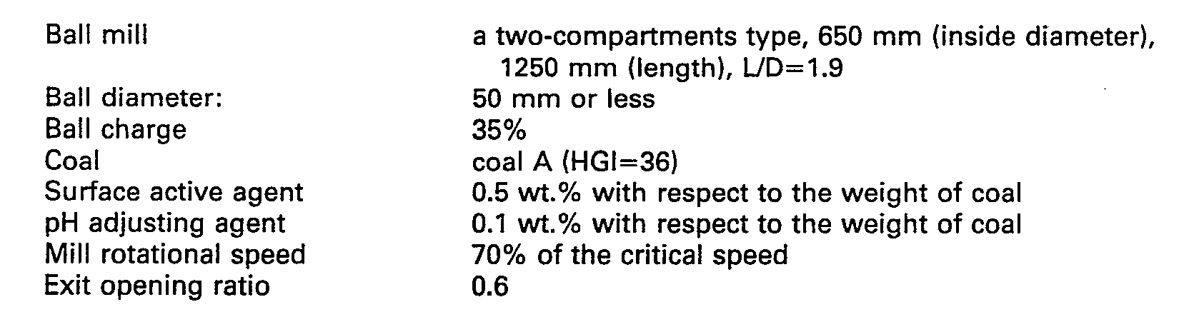
- As a result of tests conducted by charging the feed rate of particles ground and the concentration of coal under the conditions listed above, the conditions for maintaining the slurry viscosity at about 1,000 cp and the amount of particles passing through the 200-mesh screen at 75% were 60 kg/h in terms of the amount of particles ground and 63 wt.% in terms of the concentration of coal. At that time, the specific power consumption was approximately 47 kWh/t coal. Thus, when producing the slurry of the same viscosity and particle size, the level of power consumption for grinding the slurry having a 0.5% higher concentration than the prior art can be reduced from 87 kWh/t to 47 kWh/t, and the amount of the surface active agent used can be reduced from 0.7% to 0.5%. This is attributable to the fact that the mill exit opening ratio Dd/D was set at 0.6 to maintain the fractional ball space filling of the slurry Us at 0.6, and that the ball mill was partitioned into two compartments, the first compartment on the entrance side being filled with large-diameter balls and the second compartment on the exit side, with small-diameter balls.
- Thus, by maintaining the ratio of the volume of the slurry to the volume of the ball space in the range of 0.1 to 1, it is possible to reduce the level of power consumption. In addition, the level of power consumption can also be reduced by setting the ratio of the mill exit diameter Dd to the mill inside diameter D, Dd/D, in the range of 0.4-0.95.
- The ball mill used in the coal-water slurry producing system shown in Fig. 1 should not be restricted to the one shown in Figs. 4 to 9. It goes without saying that a conventional ball mill can also be used in the coal-water slurry producing system concerned.
- In accordance with the present invention, there is provided an improved coal-water slurry producing system in which a strainer will not be blocked or damaged by coarse coal particles.
- In addition, in accordance with the present invention, there is provided a continuous wet-type ball mill with a reduced power consumption.
Claims (5)
Applications Claiming Priority (4)
| Application Number | Priority Date | Filing Date | Title |
|---|---|---|---|
| JP61088936A JPH0662968B2 (en) | 1986-04-17 | 1986-04-17 | Solid fuel slurry production equipment |
| JP88936/86 | 1986-04-17 | ||
| JP88933/86 | 1986-04-17 | ||
| JP61088933A JPH0645792B2 (en) | 1986-04-17 | 1986-04-17 | Method for producing solid fuel-water slurry |
Publications (3)
| Publication Number | Publication Date |
|---|---|
| EP0242218A2 EP0242218A2 (en) | 1987-10-21 |
| EP0242218A3 EP0242218A3 (en) | 1988-07-13 |
| EP0242218B1 true EP0242218B1 (en) | 1990-08-01 |
Family
ID=26430265
Family Applications (1)
| Application Number | Title | Priority Date | Filing Date |
|---|---|---|---|
| EP87303371A Expired EP0242218B1 (en) | 1986-04-17 | 1987-04-15 | Coal-water slurry producing system |
Country Status (4)
| Country | Link |
|---|---|
| US (1) | US4770352A (en) |
| EP (1) | EP0242218B1 (en) |
| CN (1) | CN1010029B (en) |
| CA (1) | CA1298259C (en) |
Families Citing this family (17)
| Publication number | Priority date | Publication date | Assignee | Title |
|---|---|---|---|---|
| US4989794A (en) * | 1986-07-16 | 1991-02-05 | Alcan International Limited | Method of producing fine particles |
| JPH0775675B2 (en) * | 1989-02-23 | 1995-08-16 | ナカヤ実業株式会社 | Crushed sand production equipment for concrete |
| USH1161H (en) | 1989-10-30 | 1993-04-06 | The United States Of America As Represented By The United States Department Of Energy | Aqueous coal slurry |
| GB9204493D0 (en) * | 1992-03-02 | 1992-04-15 | British Telecomm | Optical communications |
| US5269234A (en) * | 1992-10-20 | 1993-12-14 | Continental Cement Company | Method for processing solid, Hazardous waste material for use as a fuel |
| US6662951B1 (en) * | 2000-09-27 | 2003-12-16 | Basic Resources, Inc. | Process for extracting and purifying naturally occurring zeolite |
| CN103965981B (en) | 2013-01-31 | 2016-05-25 | 通用电气公司 | The apparatus and method of preparation water-coal-slurry |
| CN104289278A (en) * | 2013-07-16 | 2015-01-21 | 张志军 | Wet overflow ball mill |
| CN103464266A (en) * | 2013-09-17 | 2013-12-25 | 朱回军 | High-concentration dry-method pulping process of grinding machine |
| CN104002382B (en) * | 2014-05-22 | 2016-06-22 | 贵州开磷集团股份有限公司 | A kind of ardealite filling in mine conveying engineering pulping process |
| CN104069932B (en) * | 2014-06-30 | 2016-01-06 | 玖龙纸业(太仓)有限公司 | Ore lapping device |
| CN104785329A (en) * | 2015-04-14 | 2015-07-22 | 柳州煜华科技有限公司 | Crushing water washing drum sorting machine |
| CN105956334B (en) * | 2016-06-02 | 2019-06-18 | 中国人民解放军61599部队计算所 | Construction method of mill load parameter inference model based on numerical simulation |
| CN110586264A (en) * | 2018-06-12 | 2019-12-20 | 台山市金昊贸易有限公司 | Ball mill capable of reducing temperature |
| DE102019133787A1 (en) * | 2019-12-10 | 2021-06-10 | Fraunhofer-Gesellschaft zur Förderung der angewandten Forschung eingetragener Verein | Rotating grinding media mill for the production of polyisoprene and / or other non-polar materials |
| CN115350748B (en) * | 2022-08-18 | 2023-07-25 | 安徽理工大学 | Coal water slurry concentration device |
| CN118681645B (en) * | 2024-06-05 | 2025-12-05 | 南充三环电子有限公司 | A ball mill jar, ball milling equipment and its application |
Family Cites Families (14)
| Publication number | Priority date | Publication date | Assignee | Title |
|---|---|---|---|---|
| US1461977A (en) * | 1923-07-17 | Sydney edward thacker ewing and joseph leonard willey | ||
| US1670005A (en) * | 1925-07-23 | 1928-05-15 | Pratt James Burton | Quartz mill |
| US1787897A (en) * | 1929-08-13 | 1931-01-06 | Joseph V Durnin | Compartment tube grinding mill |
| US2160169A (en) * | 1936-06-18 | 1939-05-30 | Smidth & Co As F L | Mill |
| NL103261C (en) * | 1954-12-17 | |||
| DE1131974B (en) * | 1959-07-07 | 1962-06-20 | Schenck Gmbh Carl | Process for regulating the degree of filling of container mills |
| US3078050A (en) * | 1960-01-08 | 1963-02-19 | Hardinge Harlowe | Autogenous grinding process and mill systems to perform the same |
| GB1037350A (en) * | 1965-05-04 | 1966-07-27 | Smidth & Co As F L | Method of making a slurry and compartment mill for carrying out the method |
| GB1159259A (en) * | 1966-12-08 | 1969-07-23 | Smidth & Co As F L | Method of and Mills for Grinding Mineral Materials |
| CH505651A (en) * | 1968-03-21 | 1971-04-15 | Escher Wyss Ag | Device for grinding and sifting a granular material, in particular cement |
| US3887142A (en) * | 1973-06-21 | 1975-06-03 | Richard E Mcelvain | Ore grinding circuit |
| JPS5856559B2 (en) * | 1978-02-23 | 1983-12-15 | 電源開発株式会社 | Slurry manufacturing equipment |
| SU1103895A1 (en) * | 1981-10-08 | 1984-07-23 | Государственный Всесоюзный Научно-Исследовательский Институт Цементной Промышленности "Ниицемент" | Method of obtaining fine-milled materials in tubular multiple-compartment mill and tubular mill |
| AU545527B2 (en) * | 1981-12-03 | 1985-07-18 | Electric Power Development Co. Ltd. | Production of high concentration of coal |
-
1987
- 1987-04-15 EP EP87303371A patent/EP0242218B1/en not_active Expired
- 1987-04-16 CA CA000534892A patent/CA1298259C/en not_active Expired - Lifetime
- 1987-04-17 US US07/039,274 patent/US4770352A/en not_active Expired - Lifetime
- 1987-04-17 CN CN87102798.4A patent/CN1010029B/en not_active Expired
Also Published As
| Publication number | Publication date |
|---|---|
| EP0242218A3 (en) | 1988-07-13 |
| CN87102798A (en) | 1987-11-18 |
| US4770352A (en) | 1988-09-13 |
| EP0242218A2 (en) | 1987-10-21 |
| CA1298259C (en) | 1992-03-31 |
| CN1010029B (en) | 1990-10-17 |
Similar Documents
| Publication | Publication Date | Title |
|---|---|---|
| US4770352A (en) | Coal-water slurry producing system | |
| CN103899280B (en) | Well drilling waste reinjection system and method | |
| AU727868B2 (en) | Coal preparation system | |
| US20200238291A1 (en) | Mill | |
| US6214237B1 (en) | Process for treating solid waste slurry | |
| EP0130788B1 (en) | Process for producing a coal-water slurry | |
| CA2235938C (en) | Apparatus for preparing a pumpable oil sand and water slurry | |
| US3485534A (en) | Deep mine ore retrieval system | |
| JP2579984B2 (en) | Method for producing granular material and apparatus for producing the same | |
| RU2601648C1 (en) | Process line for processing ash-slag wastes | |
| EP1770819B1 (en) | System and method for treating lead containing devices | |
| CA2697899C (en) | Grinding circuit with cyclone and density separator classification system and method | |
| CN115301402A (en) | Dry-type fluidization ore dressing device | |
| CN220736436U (en) | Three-stage screening concentration type solid-liquid separator | |
| CN213079126U (en) | Impurity removing device for coal water slurry | |
| CN224127436U (en) | Single base powder reducing mechanism | |
| CN220531874U (en) | Ore dressing system of iron ore | |
| EP0157307B1 (en) | Apparatus for preparing coal slurry of high concentration | |
| JPS6157251A (en) | Wet tube mill | |
| CN214654356U (en) | All-in-one is selected and washd in pulping | |
| JP2534022B2 (en) | Method for producing high-concentration coal-water slurry | |
| JPH0318492Y2 (en) | ||
| SU1060793A1 (en) | Method of averaging loose materials | |
| JPH036960B2 (en) | ||
| RU2598613C1 (en) | Process line for processing ash-slag wastes |
Legal Events
| Date | Code | Title | Description |
|---|---|---|---|
| PUAI | Public reference made under article 153(3) epc to a published international application that has entered the european phase |
Free format text: ORIGINAL CODE: 0009012 |
|
| AK | Designated contracting states |
Kind code of ref document: A2 Designated state(s): FR GB IT |
|
| PUAL | Search report despatched |
Free format text: ORIGINAL CODE: 0009013 |
|
| AK | Designated contracting states |
Kind code of ref document: A3 Designated state(s): FR GB IT |
|
| 17P | Request for examination filed |
Effective date: 19880830 |
|
| 17Q | First examination report despatched |
Effective date: 19881028 |
|
| RAP1 | Party data changed (applicant data changed or rights of an application transferred) |
Owner name: BABCOCK-HITACHI KABUSHIKI KAISHA |
|
| GRAA | (expected) grant |
Free format text: ORIGINAL CODE: 0009210 |
|
| AK | Designated contracting states |
Kind code of ref document: B1 Designated state(s): FR GB IT |
|
| ITF | It: translation for a ep patent filed | ||
| ET | Fr: translation filed | ||
| PLBE | No opposition filed within time limit |
Free format text: ORIGINAL CODE: 0009261 |
|
| STAA | Information on the status of an ep patent application or granted ep patent |
Free format text: STATUS: NO OPPOSITION FILED WITHIN TIME LIMIT |
|
| 26N | No opposition filed | ||
| ITTA | It: last paid annual fee | ||
| REG | Reference to a national code |
Ref country code: GB Ref legal event code: IF02 |
|
| PGFP | Annual fee paid to national office [announced via postgrant information from national office to epo] |
Ref country code: FR Payment date: 20040218 Year of fee payment: 18 |
|
| PGFP | Annual fee paid to national office [announced via postgrant information from national office to epo] |
Ref country code: GB Payment date: 20040414 Year of fee payment: 18 |
|
| PG25 | Lapsed in a contracting state [announced via postgrant information from national office to epo] |
Ref country code: FR Free format text: LAPSE BECAUSE OF NON-PAYMENT OF DUE FEES Effective date: 20041231 |
|
| REG | Reference to a national code |
Ref country code: FR Ref legal event code: ST |
|
| PG25 | Lapsed in a contracting state [announced via postgrant information from national office to epo] |
Ref country code: IT Free format text: LAPSE BECAUSE OF NON-PAYMENT OF DUE FEES;WARNING: LAPSES OF ITALIAN PATENTS WITH EFFECTIVE DATE BEFORE 2007 MAY HAVE OCCURRED AT ANY TIME BEFORE 2007. THE CORRECT EFFECTIVE DATE MAY BE DIFFERENT FROM THE ONE RECORDED. Effective date: 20050415 Ref country code: GB Free format text: LAPSE BECAUSE OF NON-PAYMENT OF DUE FEES Effective date: 20050415 |
|
| GBPC | Gb: european patent ceased through non-payment of renewal fee |
Effective date: 20050415 |