EP0242142A2 - System for adjusting signal transmission timing to prevent signal collisions - Google Patents
System for adjusting signal transmission timing to prevent signal collisions Download PDFInfo
- Publication number
- EP0242142A2 EP0242142A2 EP87303164A EP87303164A EP0242142A2 EP 0242142 A2 EP0242142 A2 EP 0242142A2 EP 87303164 A EP87303164 A EP 87303164A EP 87303164 A EP87303164 A EP 87303164A EP 0242142 A2 EP0242142 A2 EP 0242142A2
- Authority
- EP
- European Patent Office
- Prior art keywords
- signal
- equipment unit
- terminal equipment
- central
- delay
- Prior art date
- Legal status (The legal status is an assumption and is not a legal conclusion. Google has not performed a legal analysis and makes no representation as to the accuracy of the status listed.)
- Granted
Links
Images


Classifications
-
- H—ELECTRICITY
- H04—ELECTRIC COMMUNICATION TECHNIQUE
- H04J—MULTIPLEX COMMUNICATION
- H04J3/00—Time-division multiplex systems
- H04J3/02—Details
- H04J3/06—Synchronising arrangements
- H04J3/0635—Clock or time synchronisation in a network
- H04J3/0682—Clock or time synchronisation in a network by delay compensation, e.g. by compensation of propagation delay or variations thereof, by ranging
-
- H—ELECTRICITY
- H04—ELECTRIC COMMUNICATION TECHNIQUE
- H04L—TRANSMISSION OF DIGITAL INFORMATION, e.g. TELEGRAPHIC COMMUNICATION
- H04L12/00—Data switching networks
- H04L12/28—Data switching networks characterised by path configuration, e.g. LAN [Local Area Networks] or WAN [Wide Area Networks]
Definitions
- the present invention relates to a signal transmission system in a communication network system wherein one central equipment unit and a plurality of terminal equipment units are connected via a signal transmission line and, more particularly, to a system for adjusting a signal transmission timing at each terminal equipment unit, for the purpose of preventing signal collisions on the signal transmission line.
- a communication network is known, which is constructed such that a terminal equipment unit having concentration and distribution functions is installed in a building or at a floor of the building, at least one terminal device such as a telephone set is connected to the terminal equipment unit, and a plurality of such terminal equipment units are coupled to a central equipment unit such as a PBX (private branch exchange) via an up link and a down link.
- PBX private branch exchange
- the terminal equipment units are connected at different positions along the signal transmission line. For this reason, the signal propagation times (transmission delay times) between the respective terminal equipment units and the central equipment unit differ from each other.
- transmission delay times transmission delay times
- simply setting time margins for signal transmissions while taking into consideration the different transmission delay times of the terminal equipment units would considerably reduce the utility efficiency of the transmission line.
- This system operates in a test mode, a transmission-start timing setting mode, and a normal data transmission mode.
- a central equipment unit transmits test signals addressed to the terminal equipment units, and each terminal equipment unit transmits a response signal to the central equipment unit, in response to the reception of the test signal addressed to itself.
- the central equipment unit measures a delay time between the transmission timing of the test signal and the reception timing of the response signal transmitted from the terminal equipment unit.
- the central equipment unit transmits control data based on the measured delay time to each terminal equipment unit.
- each terminal equipment unit transmits a data signal to the central equipment unit at a timing based on the control data transmitted from the central equipment unit.
- the delay time measurement mode and the data transmission mode are provided independently from each other, if an additional terminal equipment unit is connected to the network, it is difficult to measure a transmission delay time between the additional terminal equipment unit and the central equipment unit. In other words, the delay time between the additional terminal equipment unit and the central equipment unit must be measured when the existing terminal equipment units are not busy.
- the central equipment unit requests each terminal equipment unit to transmit a test signal, and the terminal equipment unit requested to do so, transmits the test signal.
- the central equipment unit sends the test signal, transmitted from the terminal equipment unit, back to the terminal equipment unit, without performing any processing.
- the terminal equipment unit measures a transmission delay time between the transmission timing of the test signal and reception timing of the test signal sent back from the central equipment unit, and adjusts the transmission timing of a data signal for the central equipment unit in accordance with the measured transmission delay time.
- One transmission frame of the system includes a data transmission interval having time slots assigned to the respective terminal equipment units, and a window interval for measuring delay times.
- the window interval includes an address field for designating one of the terminal equipment units to transmit the test signal, and a test signal transmission/receiving field in which a terminal equipment unit transmits a test signal to the central equipment unit and receives the test signal sent back therefrom. Only the test signal transmission/reception field is used to transmit/receive the test signal for delay measurement, and the address field cannot be used therefor. For this reason, a time interval of a delay measurement window must be set relatively long, thus reducing the utility efficiency of time slots for data transmission.
- each terminal equipment unit since each terminal equipment unit must receive a data signal transmitted from the central equipment unit and the test signal transmitted by itself, it is difficult to stably receive these signals. In other words, an expensive receiving device is required to ensure stable reception of the signals.
- a communication network system comprises: a central equipment unit; a plurality of terminal equipment units, each of the terminal equipment units having at least one terminal device connected thereto; and a signal transmission line connected between the central equipment unit and the terminal equipment units, and having an up link and a down link.
- the central equipment unit comprises means for providing reference timings, and means for transmitting a frame signal, consisting of a delay measurement window field and a data field wherein subframe information signals are arranged on a time-division multiplexing basis, onto the down link, every time a reference timing arrives, the delay measurement window field of the frame signal having an address field carrying address information designating one of the terminal equipment units for a measurement of a delay time of a signal transmission between said central equipment unit and the terminal equipment unit.
- Each of the terminal equipment units comprises means for transmitting a response signal onto the up link, after a predetermined time interval from the reception timing of a frame signal, transmitted from the central equipment unit and having the address field carrying address information designating itself, such that the response signal arrives at the central equipment unit within the delay measurement window field of the next frame signal, the response signal carrying self address information.
- the central equipment unit further comprises means for measuring a delay time between the reference timing for transmitting the next frame signal and the reception timing of the response signal; and means for transmitting transmission timing adjustment information based on the measured delay time, and address information of the terminal equipment unit, which has transmitted the response signal, in the address field of the next frame signal.
- Each of the terminal equipment units further comprises means for transmitting a subframe signal after a time interval, depending on the transmission timing adjustment information, from the reception timing of a frame signal.
- central equipment unit l including a PBX, and a plurality of terminal equipment units 21, 22, ..., 2 n , each having concentration and distribution functions, are disposed at locations remote from one another.
- a bus-cofigured signal transmission line having up link 3 and down link 4 is extended from central equipment unit l, and each terminal equipment unit is connected at a different position on the signal transmission line. Therefore, a signal transmission time between each terminal equipment unit and central equipment unit l depends on a position where the terminal equipment unit is connected to the signal transmission line.
- To each terminal equipment unit is connected at least one terminal device 5 such as a telephone set or a data processing device. The number of terminal devices 5 connected to a terminal equipment unit need not be constant.
- the terminal equipment units are assigned with numbers (addresses) #l, #2, ..., #i, ..., #n.
- Central equipment unit l transmits subframe data signals addressed to the respective terminal equipment units over down link 4 on a time-division multiplexing basis within one frame interval, and the respective terminal equipment units sequentially transmit subframe data signals to central equipment unit l over up link 3.
- the signal transmission line may be a frequency multiplex transmission line in which the up link and the down link are adapted for different transmission frequency bands, or two separate transmission lines may be used for signal transmission in the same transmission frequency band.
- one of the terminal equipment units is designated every frame interval, and the designated terminal equipment unit transmits a response signal to the central equipment unit.
- the central equipment unit measures a time (transmission delay time) between a reference timing in one frame interval and a receiving timing of the response signal transmitted from the terminal equipment unit, and transmits measured data to the terminal equipment unit, so that the terminal equipment unit adjusts a transmission start timing of a data signal (subframe signal) for the central equipment unit.
- the format includes a field of a frame sync signal (FS) or a frame delimiter, a field of an assignment signal (ASGi) including address information for designating a terminal equipment unit having an address number i or an address field, a dummy data field, and a data field including subframe signals DOl, DO2, ..., DOn addressed to the respective terminal equipment units 21, 22,..., 2 n .
- an assignment signal (ASGi+l) for designating a terminal equipment unit having an address number i+l is transmitted.
- the subframe signal is transmitted in a time slot (TS) assigned to the corresponding terminal equipment unit.
- TS time slot
- the frame signals may be continuously transmitted from the central equipment unit to the respective terminal equipment units via the down link.
- the FS field, the ASG field, and the dummy data field are adapted for a window for measuring the transmission delay times.
- response signal RSPi-l is transmitted from the terminal equipment unit having address number i-l and designated by signal ASGi-l in the previous frame signal, and then subframe data signals DIl, DI2, ..., DIn are transmitted from the respective terminal equipment units. These subframe data signals are transmitted in time slots assigned to the respective terminal equipment units.
- a response signal, following signal RSPi-l, is RSPi transmitted from a terminal equipment unit having address number i and designated by signal ASGi.
- Signal RSPi-l is only required to reach the central equipment unit within a delay measurement window of a frame signal carrying ASGi signal. A timing at which a response signal reaches the central equipment unit within the delay measurement window depends on the position of a terminal equipment unit transmitted the response signal.
- each terminal equipment unit measures a transmission delay time.
- a terminal equipment unit designated by signal ASGi transmitted from the central equipment unit transmits signal RSPi to the central equipment unit via the up link, and receives signal RSPi sent back from the central equipment unit via the down link.
- the delay measurement window adapted for transmitting and receiving signal RSPi is limited within an interval between the ASGi field and the data field, as shown in Fig. 3. Therefore, since a time interval which cannot be used for the delay measurement increases as compared with the system according to the present invention, it is difficult to increase time slots used for data signal tranmissions. As a result, the utility efficiency of the time slots is reduced.
- a transmission initiation timing of a frame signal is set to a reference timing of the central equipment unit.
- the frame signal reaches terminal equipment unit 2i, having address i , via the down link with a certain delay time.
- the terminal equipment unit generates a first TRANSMIT ENABLE signal TRENl to transmit to RSP signal after a predetermined period TXTo of time, which substantially corresponds to a frame interval, from a reception start timing (reference timing of the terminal equipment unit) of the frame signal.
- the RSP signal is transmitted to the central equipment unit over the up link, and the central equipment unit measures a time difference ⁇ T ( ⁇ 0) between the next frame reference timing and a reception timing of the RSP signal.
- the terminal equipment unit generates a TRANSMIT ENABLE signal TREN2 after a delay of time TXT from the reference timing.
- TREN2 Transmission Timing ENABLE signal
- the RSP signal is transmitted at the timing when signal TREN2 is generated, the RSP signal arrives at the central equipment unit at the reference timing of the next frame.
- the RSP signal need not be transmitted in response to signal TREN2, and a generation timing of signal TREN2 is utilized as a reference timing for the corresponding terminal equipment unit to transmit the subframe signal to the central equipment unit.
- Figs. 5A and 5B respectively show examples of formats of signal ASGi for requesting the terminal equipment unit 2i to transmit the response signal, and response signal RSPi transmitted from the terminal equipment unit 2i.
- signal ASGi includes an ASG delimiter (32 bits), address information I (i-l, l6 bits) of the terminal equipment unit 2i-l which has already transmitted response signal RSPi-l, corrected transmission timing control information (TXT, l6 bits) for the terminal equipment unit 2i-l, address information II (i, l6 bits) of the terminal equipment unit 2i which is requested to transmit the response signal, and error detection signal CRC (l6 bits).
- Signal RSPi includes a sync signal (24 bits), address information (i, l6 bits) representing a source of signal RSPi, transmission timing information (TXTo, l6 bits), and error detection signal CRC (l6 bits).
- Diplexer 6l is provided, which applies a received signal, transmitted from the terminal equipment units over up link 3, to demodulator 62.
- Demodulator 62 demodulates the received signal and forms a carrier sense signal CS.
- the demodulated signal is applied to frame disassembler 63, delay measurement module 64, and ASG/RSP processing module 65.
- Carrier sense signal CS is applied to frame disassembler 63 and delay measurement module 64.
- Frame disassembler 63 disassembles the subframe signal transmitted from a terminal equipment unit and included in the demodulated signal, and supplies audio PCM data and control data to PBX 66, respectively, through a PCM highway (HW) and a data highway (HW).
- PBX 66 performs exchange processing of data signals transmitted from the terminal equipment units, and supplies audio PCM data and control data to frame assembler 67, respectively, through PCM HW and data HW.
- PBX 66 supplies 2.048-MHz PCM clock signal PCM CLK and a PCM HW frame sync signal to clock generator 68 which generates master clock ⁇ l (4.096 MHz), delay measurement clock ⁇ 2 (65.536 MHz), and a sequencer master count outputs (0 to 7FFF H) synchronous with clock ⁇ 2.
- master clock ⁇ l 4.096 MHz
- delay measurement clock ⁇ 2 (65.536 MHz)
- sequencer master count outputs (0 to 7FFF H) synchronous with clock ⁇ 2.
- Frame assembler 67 assembles PCM data (3 bits) and control data (l bit), supplied from PBX 66 and addressed to one terminal equipment unit, into a subframe data signal for a time slot assigned to the terminal equipment unit, and sends the subframe data signal to selector/CRC generator 69.
- Selector 69 selects subframe signals generated by assembler 67 and ASG signal (including the frame sync signal and dummy data) generated by module 65 in accordance with the format of the frame signal shown in Fig. 2 for application to modulator 70.
- an output of selector 69 has 2 bits. This is because an output signal of selector 69 is subjected to quadrature phase shift keying in modulator 70.
- delay measurement module 64 In response to the demodulated data signal and carrier sense signal CS supplied from demodulator 62, delay measurement module 64 generates information ⁇ T which represents a time difference between the transmission start timing of the frame signal and the reception timing of the RSP signal, clock signal RSP CLK (4.096 MHz) recovered from the demodulated RSP signal, and an RSP nondetection signal which represents that the RSP signal could not be detected within a predetermined interval, these signals being applied to AGS/RSP processing module 65. Module 65 generates signal ASGi in the format consisting of fields from the ASG delimiter to terminal address II, as shown in Fig. 5A.
- the CRC signal is generated in generator 69 and added subsequent to the field of terminal address II of signal ASGi. As shown in Fig. 2, the CRC signal is generated based on signals existing from the dummy data field of one frame signal to the field of terminal address II in the ASG signal of the next frame signal.
- delay measurement module 64 includes timing generator 7l, RSP sync pattern detector 72, down counter 73, and register 74 into which an initial value of delay measurement information is preset.
- timing generator 7l supplies a delay measurement start signal (load instruction) to down counter 73 so that the initial value of register 74 is loaded into down counter 73.
- Timing generator 7l generates an RSP detection window signal at a timing when the RSP signal is likely to be received and supplies it to RSP sync pattern detector 72.
- Detector 72 is set ready for detecting RSP signal by the window signal, and responsive to carrier sense signal CS and the demodulated data signal supplied from demodulator 62 to detect the RSP signal.
- detector 72 supplies a count stop signal to counter 73.
- detector 72 recovers clock signal RSP CLK from the RSP signal, and generates the RSP nondetection signal when the RSP signal is not detected.
- down counter 73 In response to the start signal obtained from timing generator 7l which coincides with a transmission start timing of one frame signal in central equipment unit l, down counter 73 starts a down count. In response to the stop signal obtained from RSP sync pattern detector 72 which coincides with the RSP signal detection timing, counter 73 stops the down count. The count of counter 73, obtained when the down count is stopped, represents a time difference ⁇ T between the transmission start timing (reference timing) of the frame signal and the RSP signal reception (detection) timing (Fig. 4).
- the reference timing of central equipment l i.e., the down count start timing of down counter 73 is set to the timing when the master count, indicating a count from 0 to 7FFF H , indicates 0, and the start signal for down counter 73 is generated at this timing.
- a frame signal transmission is started from the frame sync signal FS.
- RSP sync pattern detector 72 detects whether an output signal of demodulator 62 remains low during a period of eight clocks of delay measurement clock ⁇ 2 (4.098 MHz ⁇ l6) after carrier sense signal CS is applied. If this is detected, an RSP detection pulse is generated after a delay of l/2 bit time from a transition of the sync pattern from a high level to a low level.
- ASG/RSP processing module 65 will be described below with reference to Fig. l0.
- Module 65 includes serial to parallel conversion shift register 8l, central processing unit (CPU) 82, RAM/ROM 83 for storing data and CPU programs, parallel to serial conversion shift register 84, decoder 85, clock counter 86, interrupt controller (counter/timer controller) 87, and ASG output controller 88.
- Shift register 8l receives a demodulated signal from demodulator 62 in response to clock RSP CLK. More specifically, register 8l is adapted to receive the RSP signal sync field, the terminal address field, and the timing data field shown in Fig. 5B. Decoder 85 decodes "0" of the master count to reset counter 86. Counter 86 counts clock RSP CLK. When the desired data fields are loaded into register 8l, counter 86 instructs controller 87 to cause CPU 82 to receive the data from register 8l.
- CPU 82 assembles the ASG delimiter field, the terminal address field (#i-l), the timing data field (TXT), and the terminal address field (#i) as shown in Fig. 5A, following frame sync field FS.
- the terminal address field (#i) is adapted to poll the terminal equipment unit having address i for the purpose of measuring a transmission delay time.
- CPU 82 loads such assembled data into register 84.
- Controller 88 supplies the data loaded in register 84, in response to the master count "0", to selector/CRC generator 69 for transmission to the terminal equipment units.
- Diplexer 9l is connected to the signal transmission line and applies a frame signal transmitted from central equipment unit l to demodulator 92.
- a demodulated data signal is applied to receive clock recovery circuit 93 where 4.096-MHz receive clock ⁇ l ⁇ is recovered from the demodulated data signal and frequency-multiplied by a factor of l6 to generate 65.536-MHz transmission timing adjustment clock ⁇ 2 ⁇ .
- the demodulated data signal is also applied to ASG/RSP processing module 94 and CRC checking circuit 95.
- Module 94 detects polling address information II, addressed to itself and included in the ASG signal, so as to generate the RSP signal, and extracts timing adjustment information TXT addressed to itself from the ASG signal after the delay time measurement.
- CRC checking circuit 95 checks the CRC signal included in the ASG signal. If an error is detected, circuit 95 generates an error indication signal to disable ASG/RSP processing module 94.
- Transmission timing module 96 receives the demodulated data signal, transmission timing adjusting clock ⁇ 2 ⁇ , and transmission timing information TXT extracted by module 94 and generates transmission enable signals TRENl and TREN2 shown in Fig. 4, and 4.096-MHz transmission clock TX CLK.
- module 94 outputs the RSP signal for the delay time measurement after a delay of time TXTo from the detection timing of the frame signal.
- the RSP signal is supplied to modulator 98 through OR gate 97 and a modulated signal is applied to diplexer 9l for transmission to central equipment unit l over up link 3.
- the demodulated output signal of demodulator 92 is applied to subframe disassembler 99.
- disassembler 99 disassembles the subframe data addressed to itself from central equipment unit l, and supplies audio PCM data and control data such as a ringing control signal for terminal device 5 to subscriber line interface l00.
- Interface l00 supplies audio PCM data and control data such as a hook/dial pulse generated by device 5 to self-time slot assembler l0l.
- Assembler l0l is responsive to the time-slot data supplied from module 94, signal TREN2 supplied from module 96, and clock TX CLK to apply a subframe data signal, in a time slot assigned to itself, to modulator 98 through OR gate 97.
- the subframe data signal is modulated and applied to diplexer 9l for transmission over up link 3.
- Assembler l0l counts clocks TX CLK for a predetermined number corresponding to t ⁇ in response to signal TREN2, and outputs the subframe signal when counting the predetermined number of clocks TX CLK.
- Fig. l2 shows ASG/RSP processing module 94.
- Delimiter detector ll0 detects an ASG delimiter signal from demodulated data signal supplied from demodulator 92. When the ASG delimiter signal is detected, detector ll0 enables shift register lll to receive address information I, timing information TXT, and address information II contained in the ASG signal. When the above information is loaded into register lll, detector ll0 causes CPU ll2 to receive the contents of register lll. To CPU ll2 is applied the address information of the self terminal equipment unit provided by address dip switches ll3.
- CPU ll2 is programmed by ROM ll4 and detects whether or not the address information supplied from register lll is the self address.
- Fig. l3 shows an arrangement of transmission timing module 96.
- a low level period of one bit time is present at a predetermined position of frame sync signal FS of the frame signal transmitted from central equipment unit l.
- ASG pattern detector l2l detects the predetermined pattern of the frame sync signal in response to the demodulated data signal, clock RX CLK, and clock ⁇ 2 ⁇ .
- the detection timing of the predetermined pattern provides the reference timing of the terminal equipment unit.
- initial value TXTo preset in register l23 is loaded into down counter l22, and timing adjustment information TXT provided from module 94 is loaded into down counter l24.
- Counters l22 and l24 are counted down by transmission timing adjusting clock ⁇ 2 ⁇ . When counted down to 0, counter l22 generates RSP signal transmission enable signal TRENl. When counted down to 0, counter l24 generates subframe (time slot) data transmission enable signal TREN2. Counter l24 may be arranged to generate transmission clock TX CLK.
- the central equipment unit transmits the ASG signal to the terminal equipment units, and each terminal equipment unit transmits the RSP signal to the central equipment unit in response to the ASG signal addressed thereto. That is, unlike the prior invention described above, each terminal equipment unit is not required to receive a signal which has been transmitted by itself and then sent back from the central equipment unit as it is, but is only required to receive signals generated by the central equipment unit. Thus each terminal equipment unit can stably receive signals. Therefore, a demodulator may be simple in construction.
- the present invention is not limited to the above embodiment.
- the description has been made of the case wherein a predetermined time slot is fixedly assigned to a terminal equipment unit.
- the system of the present invention may be applied to a demand assign system in which each terminal equipment unit demands a time slot, and the central equipment unit assigns time slots to the terminal equipment units on demand.
- the demand assign system it is required that the RSP signal be transmitted in response to transmission enable signal TREN2 after the measurement of a delay time. By doing so, the RSP signal arrives at the central equipment unit at a predetermined timing of one frame interval. This increases the flexibility of a frame arrangement.
- the formats of the ASG and RSP signals are not limited to those shown in Figs. 5A and 5B.
- the ASG and RSP signals may include control information as needed.
- the control information may carry information of a time slot assigned to a terminal equipment unit on demand.
- the timing t ⁇ at which each terminal equipment unit transmits a subframe signal varies in accordance with the time slot information.
Landscapes
- Engineering & Computer Science (AREA)
- Computer Networks & Wireless Communication (AREA)
- Signal Processing (AREA)
- Time-Division Multiplex Systems (AREA)
- Small-Scale Networks (AREA)
Abstract
Description
- The present invention relates to a signal transmission system in a communication network system wherein one central equipment unit and a plurality of terminal equipment units are connected via a signal transmission line and, more particularly, to a system for adjusting a signal transmission timing at each terminal equipment unit, for the purpose of preventing signal collisions on the signal transmission line.
- A communication network is known, which is constructed such that a terminal equipment unit having concentration and distribution functions is installed in a building or at a floor of the building, at least one terminal device such as a telephone set is connected to the terminal equipment unit, and a plurality of such terminal equipment units are coupled to a central equipment unit such as a PBX (private branch exchange) via an up link and a down link.
- In such a network, the terminal equipment units are connected at different positions along the signal transmission line. For this reason, the signal propagation times (transmission delay times) between the respective terminal equipment units and the central equipment unit differ from each other. In order to transmit signals on a time-division multiplexing basis from a plurality of terminal equipment units to the central unit via the common transmission line, it is very important to prevent collisions, on the signal transmission line, of signals transmitted from the terminal equipment units. In order to prevent the signal collisions, it is necessary to adjust the signal transmission timings of the terminal equipment units, taking the different transmission delay times thereof into consideration. However, simply setting time margins for signal transmissions while taking into consideration the different transmission delay times of the terminal equipment units would considerably reduce the utility efficiency of the transmission line.
- European Patent Application No. 84302l2l.3 filed March 28, l984; entitled "BUS-CONFIGURED LOCAL AREA NETWORK WITH DATA EXCHANGE CAPABILITY"; by the same applicant as this application, discloses a system for adjusting a signal transmission timing of a terminal equipment unit. This system operates in a test mode, a transmission-start timing setting mode, and a normal data transmission mode. In the test mode, a central equipment unit transmits test signals addressed to the terminal equipment units, and each terminal equipment unit transmits a response signal to the central equipment unit, in response to the reception of the test signal addressed to itself. The central equipment unit measures a delay time between the transmission timing of the test signal and the reception timing of the response signal transmitted from the terminal equipment unit. In the transmission-start timing setting mode, the central equipment unit transmits control data based on the measured delay time to each terminal equipment unit. In the transmission mode, each terminal equipment unit transmits a data signal to the central equipment unit at a timing based on the control data transmitted from the central equipment unit.
- According to the system, since the delay time measurement mode and the data transmission mode are provided independently from each other, if an additional terminal equipment unit is connected to the network, it is difficult to measure a transmission delay time between the additional terminal equipment unit and the central equipment unit. In other words, the delay time between the additional terminal equipment unit and the central equipment unit must be measured when the existing terminal equipment units are not busy.
- European Patent Application No. 85309265.8 filed December l9, l985, entitled "SYSTEM FOR ADJUSTING SIGNAL TRANSMISSION TIMING IN TIME-DIVISION MULTIPLEXING SIGNAL TRANSMISSION", by the same applicant as this application, discloses a time-division multiplexing communication network in which each terminal equipment unit measures a transmission delay time between the central equipment unit and itself, so as to adjust the timing for a signal transmission to the central equipment unit.
- According to the transmission system disclosed in the copending application, the central equipment unit requests each terminal equipment unit to transmit a test signal, and the terminal equipment unit requested to do so, transmits the test signal. The central equipment unit sends the test signal, transmitted from the terminal equipment unit, back to the terminal equipment unit, without performing any processing. The terminal equipment unit measures a transmission delay time between the transmission timing of the test signal and reception timing of the test signal sent back from the central equipment unit, and adjusts the transmission timing of a data signal for the central equipment unit in accordance with the measured transmission delay time.
- One transmission frame of the system includes a data transmission interval having time slots assigned to the respective terminal equipment units, and a window interval for measuring delay times. The window interval includes an address field for designating one of the terminal equipment units to transmit the test signal, and a test signal transmission/receiving field in which a terminal equipment unit transmits a test signal to the central equipment unit and receives the test signal sent back therefrom. Only the test signal transmission/reception field is used to transmit/receive the test signal for delay measurement, and the address field cannot be used therefor. For this reason, a time interval of a delay measurement window must be set relatively long, thus reducing the utility efficiency of time slots for data transmission. In addition, since each terminal equipment unit must receive a data signal transmitted from the central equipment unit and the test signal transmitted by itself, it is difficult to stably receive these signals. In other words, an expensive receiving device is required to ensure stable reception of the signals.
- It is, therefore, an object of the present invention to provide a communication network system capable of improving the utility efficiency of time slots adapted for data transmission to terminal equipment units.
- It is another object of the present invention to provide a communication network system which enables each terminal equipment unit to stably receive signals transmitted from a central equipment unit.
- A communication network system according to the present invention comprises: a central equipment unit; a plurality of terminal equipment units, each of the terminal equipment units having at least one terminal device connected thereto; and a signal transmission line connected between the central equipment unit and the terminal equipment units, and having an up link and a down link. The central equipment unit comprises means for providing reference timings, and means for transmitting a frame signal, consisting of a delay measurement window field and a data field wherein subframe information signals are arranged on a time-division multiplexing basis, onto the down link, every time a reference timing arrives, the delay measurement window field of the frame signal having an address field carrying address information designating one of the terminal equipment units for a measurement of a delay time of a signal transmission between said central equipment unit and the terminal equipment unit. Each of the terminal equipment units comprises means for transmitting a response signal onto the up link, after a predetermined time interval from the reception timing of a frame signal, transmitted from the central equipment unit and having the address field carrying address information designating itself, such that the response signal arrives at the central equipment unit within the delay measurement window field of the next frame signal, the response signal carrying self address information. The central equipment unit further comprises means for measuring a delay time between the reference timing for transmitting the next frame signal and the reception timing of the response signal; and means for transmitting transmission timing adjustment information based on the measured delay time, and address information of the terminal equipment unit, which has transmitted the response signal, in the address field of the next frame signal. Each of the terminal equipment units further comprises means for transmitting a subframe signal after a time interval, depending on the transmission timing adjustment information, from the reception timing of a frame signal.
- This invention can be more fully understood from the following detailed description when taken in conjunction with the accompanying drawings, in which:
- Fig. l shows a communication network to which a signal transmission system of this invention is applied;
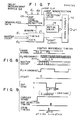
- Fig. 2 is a diagram for explaining the signal transmission of the present invention;
- Fig. 3 is a diagram for explaining a signal transmission according to the prior invention described above, for better understanding of the present invention;
- Fig. 4 is a diagram for explaining signal transmission timing adjustment of a terminal equipment unit according to the present invention;
- Fig. 5A and 5B show, by way of examples, formats of an ASG signal transmitted from a central equipment unit to terminal equipment units and an RSP signal transmitted from a terminal equipment unit to the central equipment unit, respectively;
- Fig. 6 is a block diagram of the central equipment unit according to an embodiment of the present invention;
- Fig. 7 is a block diagram of a delay measurement module of Fig. 6;
- Fig. 8 is a diagram for explaining a reference timing used in the central equipment unit;
- Fig. 9 is a diagram for explaining a transmission (detection) timing of the RSP signal transmitted from a terminal equipment unit;
- Fig. l0 is a block diagram of an ASG/RSP processing module of Fig. 6;
- Fig. ll is a block diagram of the terminal equipment unit;
- Fig. l2 is a block diagram of the ASG/RSP processing module of Fig. l0; and
- Fig. l3 is a block diagram of a transmission timing module of Fig. l0.
- A system for adjusting a signal transmission timing according to the present invention will now be described in detail with reference to a PBX network. As shown in Fig. l, central equipment unit l including a PBX, and a plurality of
terminal equipment units link 3 and downlink 4 is extended from central equipment unit l, and each terminal equipment unit is connected at a different position on the signal transmission line. Therefore, a signal transmission time between each terminal equipment unit and central equipment unit l depends on a position where the terminal equipment unit is connected to the signal transmission line. To each terminal equipment unit is connected at least one terminal device 5 such as a telephone set or a data processing device. The number of terminal devices 5 connected to a terminal equipment unit need not be constant. - The terminal equipment units are assigned with numbers (addresses) #l, #2, ..., #i, ..., #n. Central equipment unit l transmits subframe data signals addressed to the respective terminal equipment units over
down link 4 on a time-division multiplexing basis within one frame interval, and the respective terminal equipment units sequentially transmit subframe data signals to central equipment unit l over uplink 3. The signal transmission line may be a frequency multiplex transmission line in which the up link and the down link are adapted for different transmission frequency bands, or two separate transmission lines may be used for signal transmission in the same transmission frequency band. - An example of a signal transmission system according to the present invention will be described below with reference to Fig. 2. With a communication network system of the present invention, one of the terminal equipment units is designated every frame interval, and the designated terminal equipment unit transmits a response signal to the central equipment unit. The central equipment unit measures a time (transmission delay time) between a reference timing in one frame interval and a receiving timing of the response signal transmitted from the terminal equipment unit, and transmits measured data to the terminal equipment unit, so that the terminal equipment unit adjusts a transmission start timing of a data signal (subframe signal) for the central equipment unit.
- An example of a format of a frame signal transmitted from the central equipment unit to each terminal equipment unit over the down link is shown in Fig. 2. The format includes a field of a frame sync signal (FS) or a frame delimiter, a field of an assignment signal (ASGi) including address information for designating a terminal equipment unit having an address number i or an address field, a dummy data field, and a data field including subframe signals DOl, DO2, ..., DOn addressed to the respective
terminal equipment units - Over the up link, response signal RSPi-l is transmitted from the terminal equipment unit having address number i-l and designated by signal ASGi-l in the previous frame signal, and then subframe data signals DIl, DI2, ..., DIn are transmitted from the respective terminal equipment units. These subframe data signals are transmitted in time slots assigned to the respective terminal equipment units. A response signal, following signal RSPi-l, is RSPi transmitted from a terminal equipment unit having address number i and designated by signal ASGi. Signal RSPi-l is only required to reach the central equipment unit within a delay measurement window of a frame signal carrying ASGi signal. A timing at which a response signal reaches the central equipment unit within the delay measurement window depends on the position of a terminal equipment unit transmitted the response signal.
- For better understanding of advantages of the transmission system according to the present invention, the transmission system according to the above-mentioned prior invention will be described below with reference to Fig. 3. According to this system, each terminal equipment unit measures a transmission delay time. A terminal equipment unit designated by signal ASGi transmitted from the central equipment unit transmits signal RSPi to the central equipment unit via the up link, and receives signal RSPi sent back from the central equipment unit via the down link. In order for the terminal equipment unit to transmit and receive signal RSPi without a collision with a data signal transmitted from another terminal equipment unit, the delay measurement window adapted for transmitting and receiving signal RSPi is limited within an interval between the ASGi field and the data field, as shown in Fig. 3. Therefore, since a time interval which cannot be used for the delay measurement increases as compared with the system according to the present invention, it is difficult to increase time slots used for data signal tranmissions. As a result, the utility efficiency of the time slots is reduced.
- A transmission system according to the present invention will be described below with reference to Fig. 4.
- In Fig. 4, a transmission initiation timing of a frame signal, e.g., the frame sync signal, is set to a reference timing of the central equipment unit. The frame signal reaches terminal equipment unit 2i, having address i, via the down link with a certain delay time. The terminal equipment unit generates a first TRANSMIT ENABLE signal TRENl to transmit to RSP signal after a predetermined period TXTo of time, which substantially corresponds to a frame interval, from a reception start timing (reference timing of the terminal equipment unit) of the frame signal. The RSP signal is transmitted to the central equipment unit over the up link, and the central equipment unit measures a time difference ΔT (< 0) between the next frame reference timing and a reception timing of the RSP signal. The central equipment unit corrects transmission timing information for the terminal equipment unit as TXT = TXTo + ΔT in accordance with the measured time information, and transmits the corrected transmission timing information to the terminal equipment unit. The terminal equipment unit generates a TRANSMIT ENABLE signal TREN2 after a delay of time TXT from the reference timing. When the RSP signal is transmitted at the timing when signal TREN2 is generated, the RSP signal arrives at the central equipment unit at the reference timing of the next frame. The RSP signal need not be transmitted in response to signal TREN2, and a generation timing of signal TREN2 is utilized as a reference timing for the corresponding terminal equipment unit to transmit the subframe signal to the central equipment unit. That is, when a subframe data signal DI is transmitted after a delay of time tα from the generation timing of signal TREN2, signal DI arrives at the central equipment unit in the time slot assigned to the corresponding terminal equipment unit within one frame interval. Time tα is represented by tα = Ts × i + α, where Ts is a time slot length; i is an assigned time slot number (address number); and α is a time interval from the reference timing of the central equipment unit to the first time slot.
- Figs. 5A and 5B respectively show examples of formats of signal ASGi for requesting the terminal equipment unit 2i to transmit the response signal, and response signal RSPi transmitted from the terminal equipment unit 2i. As shown in Fig. 5A, signal ASGi includes an ASG delimiter (32 bits), address information I (i-l, l6 bits) of the terminal equipment unit 2i-l which has already transmitted response signal RSPi-l, corrected transmission timing control information (TXT, l6 bits) for the terminal equipment unit 2i-l, address information II (i, l6 bits) of the terminal equipment unit 2i which is requested to transmit the response signal, and error detection signal CRC (l6 bits). Signal RSPi includes a sync signal (24 bits), address information (i, l6 bits) representing a source of signal RSPi, transmission timing information (TXTo, l6 bits), and error detection signal CRC (l6 bits).
- An arrangement of central equipment unit l will be described below with reference to Fig. 6.
- Diplexer 6l is provided, which applies a received signal, transmitted from the terminal equipment units over up
link 3, todemodulator 62.Demodulator 62 demodulates the received signal and forms a carrier sense signal CS. The demodulated signal is applied to framedisassembler 63,delay measurement module 64, and ASG/RSP processing module 65. Carrier sense signal CS is applied to framedisassembler 63 and delaymeasurement module 64. -
Frame disassembler 63 disassembles the subframe signal transmitted from a terminal equipment unit and included in the demodulated signal, and supplies audio PCM data and control data to PBX 66, respectively, through a PCM highway (HW) and a data highway (HW).PBX 66 performs exchange processing of data signals transmitted from the terminal equipment units, and supplies audio PCM data and control data to frameassembler 67, respectively, through PCM HW and data HW.PBX 66 supplies 2.048-MHz PCM clock signal PCM CLK and a PCM HW frame sync signal toclock generator 68 which generates master clock øl (4.096 MHz), delay measurement clock ø2 (65.536 MHz), and a sequencer master count outputs (0 to 7FFF H) synchronous with clock ø2. These clock signals and timing signals are applied to various circuits of central equipment unit l, as shown in Fig. 6. -
Frame assembler 67 assembles PCM data (3 bits) and control data (l bit), supplied fromPBX 66 and addressed to one terminal equipment unit, into a subframe data signal for a time slot assigned to the terminal equipment unit, and sends the subframe data signal to selector/CRC generator 69.Selector 69 selects subframe signals generated byassembler 67 and ASG signal (including the frame sync signal and dummy data) generated bymodule 65 in accordance with the format of the frame signal shown in Fig. 2 for application tomodulator 70. Like outputs ofassembler 67 andmodule 65, an output ofselector 69 has 2 bits. This is because an output signal ofselector 69 is subjected to quadrature phase shift keying inmodulator 70. - In response to the demodulated data signal and carrier sense signal CS supplied from
demodulator 62,delay measurement module 64 generates information ΔT which represents a time difference between the transmission start timing of the frame signal and the reception timing of the RSP signal, clock signal RSP CLK (4.096 MHz) recovered from the demodulated RSP signal, and an RSP nondetection signal which represents that the RSP signal could not be detected within a predetermined interval, these signals being applied to AGS/RSP processing module 65.Module 65 generates signal ASGi in the format consisting of fields from the ASG delimiter to terminal address II, as shown in Fig. 5A. The CRC signal is generated ingenerator 69 and added subsequent to the field of terminal address II of signal ASGi. As shown in Fig. 2, the CRC signal is generated based on signals existing from the dummy data field of one frame signal to the field of terminal address II in the ASG signal of the next frame signal. - As shown in Fig. 7, delay
measurement module 64 includes timing generator 7l, RSPsync pattern detector 72, down counter 73, and register 74 into which an initial value of delay measurement information is preset. - In response to master clock øl, delay measurement clock ø2, and the master count output, timing generator 7l supplies a delay measurement start signal (load instruction) to down counter 73 so that the initial value of
register 74 is loaded intodown counter 73. Timing generator 7l generates an RSP detection window signal at a timing when the RSP signal is likely to be received and supplies it to RSPsync pattern detector 72.Detector 72 is set ready for detecting RSP signal by the window signal, and responsive to carrier sense signal CS and the demodulated data signal supplied fromdemodulator 62 to detect the RSP signal. Upon detection of the RSP signal,detector 72 supplies a count stop signal to counter 73. In addition to the detection of the RSP signal,detector 72 recovers clock signal RSP CLK from the RSP signal, and generates the RSP nondetection signal when the RSP signal is not detected. - In response to the start signal obtained from timing generator 7l which coincides with a transmission start timing of one frame signal in central equipment unit l, down counter 73 starts a down count. In response to the stop signal obtained from RSP
sync pattern detector 72 which coincides with the RSP signal detection timing, counter 73 stops the down count. The count ofcounter 73, obtained when the down count is stopped, represents a time difference ΔT between the transmission start timing (reference timing) of the frame signal and the RSP signal reception (detection) timing (Fig. 4). - As shown in Fig. 8, the reference timing of central equipment l, i.e., the down count start timing of
down counter 73 is set to the timing when the master count, indicating a count from 0 to 7FFFH, indicates 0, and the start signal fordown counter 73 is generated at this timing. At the same time, a frame signal transmission is started from the frame sync signal FS. - The RSP signal detection will be described below with reference to Fig. 9.
- The RSP signal sync field shown in Fig. 5A has a pattern which remains low during one bit time (= l/4.098 MHz = 244 nsec). RSP
sync pattern detector 72 detects whether an output signal ofdemodulator 62 remains low during a period of eight clocks of delay measurement clock ø2 (4.098 MHz × l6) after carrier sense signal CS is applied. If this is detected, an RSP detection pulse is generated after a delay of l/2 bit time from a transition of the sync pattern from a high level to a low level. The initial value set in theregister 74 shown in Fig. 7 is determined such that the RSP signal is detected at an ideal timing, which may be arbitrarily set, e.g., a timing around the front portion of the ASG field of a frame signal which is being transmitted from central equipment unit l. Therefore, when the RSP signal is detected at the ideal timing, ΔT = 0. When the RSP signal is detected after the ideal timing, ΔT < 0, and when the RSP signal is detected before the ideal timing, ΔT > 0. - ASG/
RSP processing module 65 will be described below with reference to Fig. l0. -
Module 65 includes serial to parallel conversion shift register 8l, central processing unit (CPU) 82, RAM/ROM 83 for storing data and CPU programs, parallel to serialconversion shift register 84,decoder 85,clock counter 86, interrupt controller (counter/timer controller) 87, andASG output controller 88. - Shift register 8l receives a demodulated signal from
demodulator 62 in response to clock RSP CLK. More specifically, register 8l is adapted to receive the RSP signal sync field, the terminal address field, and the timing data field shown in Fig. 5B.Decoder 85 decodes "0" of the master count to resetcounter 86.Counter 86 counts clock RSP CLK. When the desired data fields are loaded into register 8l, counter 86 instructscontroller 87 to causeCPU 82 to receive the data from register 8l.CPU 82 receives timing information TXTo transmitted from a terminal equipment unit, and information ΔT provided frommodule 64 to calculate TXT = TXTo + ΔT. In addition,CPU 82 assembles the ASG delimiter field, the terminal address field (#i-l), the timing data field (TXT), and the terminal address field (#i) as shown in Fig. 5A, following frame sync field FS. The terminal address field (#i-l) and the timing data field (TXT) are adapted to inform the terminal equipment unit having address number i-l of the corrected transmission timing information TXT = TXTo + ΔT. The terminal address field (#i) is adapted to poll the terminal equipment unit having address i for the purpose of measuring a transmission delay time.CPU 82 loads such assembled data intoregister 84.Controller 88 supplies the data loaded inregister 84, in response to the master count "0", to selector/CRC generator 69 for transmission to the terminal equipment units. - An arrangement of a terminal equipment unit will be described with reference to Fig. ll.
- Diplexer 9l is connected to the signal transmission line and applies a frame signal transmitted from central equipment unit l to
demodulator 92. A demodulated data signal is applied to receiveclock recovery circuit 93 where 4.096-MHz receive clock ølʹ is recovered from the demodulated data signal and frequency-multiplied by a factor of l6 to generate 65.536-MHz transmission timing adjustment clock ø2ʹ. - The demodulated data signal is also applied to ASG/
RSP processing module 94 andCRC checking circuit 95.Module 94 detects polling address information II, addressed to itself and included in the ASG signal, so as to generate the RSP signal, and extracts timing adjustment information TXT addressed to itself from the ASG signal after the delay time measurement.CRC checking circuit 95 checks the CRC signal included in the ASG signal. If an error is detected,circuit 95 generates an error indication signal to disable ASG/RSP processing module 94. -
Transmission timing module 96 receives the demodulated data signal, transmission timing adjusting clock ø2ʹ, and transmission timing information TXT extracted bymodule 94 and generates transmission enable signals TRENl and TREN2 shown in Fig. 4, and 4.096-MHz transmission clock TX CLK. In response to signal TRENl and clock TX CLK,module 94 outputs the RSP signal for the delay time measurement after a delay of time TXTo from the detection timing of the frame signal. The RSP signal is supplied tomodulator 98 through ORgate 97 and a modulated signal is applied to diplexer 9l for transmission to central equipment unit l over uplink 3. - The demodulated output signal of
demodulator 92 is applied tosubframe disassembler 99. In response to the time slot data corresponding to the self address provided bymodule 94,disassembler 99 disassembles the subframe data addressed to itself from central equipment unit l, and supplies audio PCM data and control data such as a ringing control signal for terminal device 5 to subscriber line interface l00. Interface l00 supplies audio PCM data and control data such as a hook/dial pulse generated by device 5 to self-time slot assembler l0l. Assembler l0l is responsive to the time-slot data supplied frommodule 94, signal TREN2 supplied frommodule 96, and clock TX CLK to apply a subframe data signal, in a time slot assigned to itself, to modulator 98 through ORgate 97. The subframe data signal is modulated and applied to diplexer 9l for transmission over uplink 3. The timing at which the subframe data signal is output from assembler l0l follows the timing at which signal TREN2 is generated bymodule 96 for tα = Ts × i + α. Assembler l0l counts clocks TX CLK for a predetermined number corresponding to tα in response to signal TREN2, and outputs the subframe signal when counting the predetermined number of clocks TX CLK. - Fig. l2 shows ASG/
RSP processing module 94. Delimiter detector ll0 detects an ASG delimiter signal from demodulated data signal supplied fromdemodulator 92. When the ASG delimiter signal is detected, detector ll0 enables shift register lll to receive address information I, timing information TXT, and address information II contained in the ASG signal. When the above information is loaded into register lll, detector ll0 causes CPU ll2 to receive the contents of register lll. To CPU ll2 is applied the address information of the self terminal equipment unit provided by address dip switches ll3. CPU ll2 is programmed by ROM ll4 and detects whether or not the address information supplied from register lll is the self address. When address information I (#i-l) is the self address, CPU ll2 supplies timing information TXT tomodule 96. On the other hand, when address information II (#i) is the self address, CPU ll2 generates the RSP signal and loads it into shift register ll5. In response to clock TX CLK and signal TRENl, RSP transmission controller ll6 starts the transmission of the RSP signal stored in register ll5 at the the generation timing of signal TRENl. - Fig. l3 shows an arrangement of
transmission timing module 96. A low level period of one bit time is present at a predetermined position of frame sync signal FS of the frame signal transmitted from central equipment unit l. ASG pattern detector l2l detects the predetermined pattern of the frame sync signal in response to the demodulated data signal, clock RX CLK, and clock ø2ʹ. The detection timing of the predetermined pattern provides the reference timing of the terminal equipment unit. Upon detecting the predetermined pattern, initial value TXTo preset in register l23 is loaded into down counter l22, and timing adjustment information TXT provided frommodule 94 is loaded into down counter l24. Counters l22 and l24 are counted down by transmission timing adjusting clock ø2ʹ. When counted down to 0, counter l22 generates RSP signal transmission enable signal TRENl. When counted down to 0, counter l24 generates subframe (time slot) data transmission enable signal TREN2. Counter l24 may be arranged to generate transmission clock TX CLK. - As described above, according to the present invention, the central equipment unit transmits the ASG signal to the terminal equipment units, and each terminal equipment unit transmits the RSP signal to the central equipment unit in response to the ASG signal addressed thereto. That is, unlike the prior invention described above, each terminal equipment unit is not required to receive a signal which has been transmitted by itself and then sent back from the central equipment unit as it is, but is only required to receive signals generated by the central equipment unit. Thus each terminal equipment unit can stably receive signals. Therefore, a demodulator may be simple in construction.
- The present invention is not limited to the above embodiment. The description has been made of the case wherein a predetermined time slot is fixedly assigned to a terminal equipment unit. The system of the present invention may be applied to a demand assign system in which each terminal equipment unit demands a time slot, and the central equipment unit assigns time slots to the terminal equipment units on demand. In the case of the demand assign system, it is required that the RSP signal be transmitted in response to transmission enable signal TREN2 after the measurement of a delay time. By doing so, the RSP signal arrives at the central equipment unit at a predetermined timing of one frame interval. This increases the flexibility of a frame arrangement. In addition, the formats of the ASG and RSP signals are not limited to those shown in Figs. 5A and 5B. The ASG and RSP signals may include control information as needed. In the case of the demand assign system, the control information may carry information of a time slot assigned to a terminal equipment unit on demand. In this case, the timing tα at which each terminal equipment unit transmits a subframe signal varies in accordance with the time slot information.
- In the above embodiment, the central equipment unit calculates transmission timing data TXT = TXTo + ΔT in accordance with delay measured data ΔT and transmits it to the corresponding terminal equipment unit. Alternatively, the central equipment unit may transmit delay measured data ΔT to the corresponding terminal equipment unit, and this terminal equipment unit may calculate TXT = TXTo + ΔT for adjusting the transmission timing thereof.
Claims (10)
a central equipment unit (l);
a plurality of terminal equipment units (2₁, 2₂,..., 2n), each having at least one terminal device (5) connected thereto; and
a signal transmission line connected between said central equipment unit and said terminal equipment units, and having an up link (3) and a down link (4),
characterized in that said central equipment unit comprises means (68) for providing reference timings; and means (65, 66, 67, 68, 69, 70) for transmitting a frame signal, consisting of a delay measurement window field and a data field wherein subframe information signals (DIl, DI2, ...) are arranged on a time-division multiplexing basis, onto said down link each time the reference timing arrives, the delay measurement window field of the frame signal having an address field carrying address information designating one of said terminal equipment units for a measurement of a delay time of a signal transmission between said central equipment unit and the terminal equipment unit;
that each of said terminal equipment units comprises means (94, 96, 97, 98) for transmitting a response signal (RSP) onto said up link, after a delay of a predetermined time interval (TXTo) from the reception timing of the frame signal, transmitted from said central equipment unit and having the address field carrying address information designating itself, such that the response signal arrives at said central equipment unit within the delay measurement window field of the next frame signal, the response signal carrying self address information;
that said central equipment unit further comprises means (64) for measuring a delay time (ΔT) between the reference timing for transmitting the next frame signal and the reception timing of the response signal; and means (64) for transmitting transmission timing adjustment information (TXT) based on the measured delay time, and address information of said terminal equipment unit, which has transmitted the response signal, in the address field of the next frame signal; and
that each of said terminal equipment units further comprises means (l0l) for transmitting a subframe signal (DI) after a time interval (TXT + tα), depending on the transmission timing adjustment information, from the reception timing of a frame signal.
a method of adjusting signal transmission timings of said terminal equipment units, for preventing a collision of subframe signals transmitted from said terminal equipment units on said up link, said method characterized by comprising the steps of:
periodically generating reference timings in said central equipment unit (l);
transmitting a frame signal from said central equipment unit (l) to said terminal equipment units (2₁ to 2n), over said down link (3), in response to each of the reference timings, the frame signal consisting of a delay measurement window field and a data field wherein the subframe signals (DOl to DOn) addressed to said terminal equipment units are arranged on a time-division multiplexing basis, and the delay measurement window field having an address field carrying address information designating one of said terminal equipment units for delay time measurement;
transmitting, from each of said terminal equipment units (2₁ to 2n), a response signal (RSPi) onto said up link (4), after a delay of a predetermined time interval from the reception timing of the frame signal transmitted from said central equipment unit and having an address field carrying address information designating the self terminal equipment unit, such that the response signal arrives at said central equipment unit with a delay measurement window field of the next frame signal, the response signal carrying the self address information;
measuring, in the central equipment unit (4), a delay time between the reference timing for transmitting the next frame signal and the reception timing of the response signal transmitted from said terminal equipment unit;
transmitting, from said central equipment unit (l) to a terminal equipment unit which has transmitted the response signal, transmission timing adjustment information based on the measured delay time (ΔT), and address information of said terminal equipment unit which has transmitted the response signal, in the address field of the next frame signal; and
transmitting, from each of said terminal equipment units, a subframe signal (DIl) onto said up link (3), after a delay of a time interval (TXT), depending on the transmission timing adjustment information (TXT + tα) transmitted from said central equipment unit, from the reception timing of the frame signal.
Applications Claiming Priority (2)
| Application Number | Priority Date | Filing Date | Title |
|---|---|---|---|
| JP85524/86 | 1986-04-14 | ||
| JP61085524A JPH06101737B2 (en) | 1986-04-14 | 1986-04-14 | Concentration distribution method |
Publications (3)
| Publication Number | Publication Date |
|---|---|
| EP0242142A2 true EP0242142A2 (en) | 1987-10-21 |
| EP0242142A3 EP0242142A3 (en) | 1989-08-23 |
| EP0242142B1 EP0242142B1 (en) | 1993-12-29 |
Family
ID=13861289
Family Applications (1)
| Application Number | Title | Priority Date | Filing Date |
|---|---|---|---|
| EP87303164A Expired - Lifetime EP0242142B1 (en) | 1986-04-14 | 1987-04-10 | System for adjusting signal transmission timing to prevent signal collisions |
Country Status (5)
| Country | Link |
|---|---|
| US (1) | US4811338A (en) |
| EP (1) | EP0242142B1 (en) |
| JP (1) | JPH06101737B2 (en) |
| CA (1) | CA1268869A (en) |
| DE (1) | DE3788587T2 (en) |
Cited By (6)
| Publication number | Priority date | Publication date | Assignee | Title |
|---|---|---|---|---|
| FR2636482A1 (en) * | 1988-09-13 | 1990-03-16 | Abiven Jacques | Method of synchronisation for the multiplexing of words in a fibre optics star communication network |
| EP0348095A3 (en) * | 1988-06-14 | 1991-05-02 | General Datacomm Industries, Inc. | Non-interfering method for measuring propagation delay of telecommunications network and apparatus for accomplishing same |
| EP0484793A1 (en) * | 1990-11-05 | 1992-05-13 | Koninklijke Philips Electronics N.V. | Digital audio communication system including a central processing unit and a communication station |
| US5339661A (en) * | 1990-01-17 | 1994-08-23 | Schulte-Schlagbaum Aktiengesellschaft | Magnetic card lock with key card |
| WO1997015129A1 (en) * | 1995-10-19 | 1997-04-24 | Cabletron Systems, Inc. | Method and apparatus for network access control with implicit ranging and dynamically assigned time slots |
| EP0683578A3 (en) * | 1994-05-20 | 1998-07-15 | Siemens Aktiengesellschaft | Optical TDM/TDMA-system with enlarged range |
Families Citing this family (25)
| Publication number | Priority date | Publication date | Assignee | Title |
|---|---|---|---|---|
| US5487066A (en) * | 1988-03-21 | 1996-01-23 | First Pacific Networks, Inc. | Distributed intelligence network using time and frequency multiplexing |
| FI894021A7 (en) * | 1988-08-31 | 1990-03-01 | Fujitsu Ltd | NEURON STRUCTURE. |
| US5034944A (en) * | 1988-10-31 | 1991-07-23 | At&T Bell Laboratories | Optical fiber bus controller |
| WO1990013956A1 (en) * | 1989-04-28 | 1990-11-15 | First Pacific Networks, Inc. | Distributed intelligence network using time and frequency multiplexing |
| AU639665B2 (en) * | 1989-04-28 | 1993-08-05 | Technologies Futures, Inc. d/b/a Orion Group, Inc. | Distributed intelligence network |
| US5130983A (en) * | 1990-03-27 | 1992-07-14 | Heffner Iii Horace W | Method of polling to determine service needs and the like |
| JPH0779347B2 (en) * | 1990-09-13 | 1995-08-23 | 株式会社シーエーティブイ基盤技術研究所 | Time division multiplex communication system |
| US6847611B1 (en) * | 1990-12-10 | 2005-01-25 | At&T Corp. | Traffic management for frame relay switched data service |
| DE69218913T2 (en) * | 1992-01-31 | 1997-07-17 | Cit Alcatel | Method for determining the transit time between a remote end station and a central end station, in a bidirectional point-to-multipoint transmission system |
| ZA931077B (en) | 1992-03-05 | 1994-01-04 | Qualcomm Inc | Apparatus and method for reducing message collision between mobile stations simultaneously accessing a base station in a cdma cellular communications system |
| US5335226A (en) * | 1992-06-18 | 1994-08-02 | Digital Equipment Corporation | Communications system with reliable collision detection method and apparatus |
| US6771617B1 (en) * | 1993-06-17 | 2004-08-03 | Gilat Satellite Networks, Ltd. | Frame relay protocol-based multiplex switching scheme for satellite mesh network |
| US5434850A (en) | 1993-06-17 | 1995-07-18 | Skydata Corporation | Frame relay protocol-based multiplex switching scheme for satellite |
| US5710755A (en) * | 1993-11-15 | 1998-01-20 | Pitney Bowes | Communication system for control applications |
| DE19504488C1 (en) * | 1995-02-10 | 1996-06-20 | Siemens Ag | Peripheral device initialisation method |
| US5793772A (en) * | 1995-11-29 | 1998-08-11 | Motorola, Inc. | Method and apparatus for synchronizing timing of components of a telecommunication system |
| JP3442228B2 (en) * | 1996-08-29 | 2003-09-02 | 松下電器産業株式会社 | Synchronous holding device |
| US6081524A (en) * | 1997-07-03 | 2000-06-27 | At&T Corp. | Frame relay switched data service |
| US6567420B1 (en) | 1999-04-15 | 2003-05-20 | Qualcomm, Incorporated | Method and apparatus for high rate channel access control |
| TW527796B (en) * | 2001-08-30 | 2003-04-11 | Tailyn Comm Co Ltd | ATM communication system for improving UTOPIA communication interface and method therefor |
| TWI307228B (en) * | 2002-03-25 | 2009-03-01 | Asulab Sa | A method of transmitting information between two units each provided with means for sending and/or receiving signals |
| US7668092B2 (en) * | 2002-11-21 | 2010-02-23 | Honeywell International Inc. | Data transmission system and method |
| CN102075820B (en) * | 2009-11-23 | 2015-05-20 | 中兴通讯股份有限公司 | Method and device for measuring distance in passive optical network |
| EP3761570B1 (en) * | 2019-07-02 | 2024-05-08 | Nxp B.V. | Collision detection on a can bus |
| US11392520B1 (en) * | 2021-02-03 | 2022-07-19 | Cirrus Logic, Inc. | Timing adjustment to unused unit-interval on shared data bus |
Family Cites Families (8)
| Publication number | Priority date | Publication date | Assignee | Title |
|---|---|---|---|---|
| CA1158739A (en) * | 1980-04-30 | 1983-12-13 | William Rodman | Distributed network synchronization system |
| JPS58154947A (en) * | 1982-03-10 | 1983-09-14 | Nec Corp | Time axis adjusting system of radio line by time division multiple address |
| JPS59178894A (en) * | 1983-03-30 | 1984-10-11 | Toshiba Corp | Line concentration and distribution system |
| JPS59181797A (en) * | 1983-03-31 | 1984-10-16 | Toshiba Corp | Line concentrating and distributing system |
| EP0121410B1 (en) * | 1983-03-31 | 1987-06-10 | Kabushiki Kaisha Toshiba | Bus-configured local area network with data exchange capability |
| JPS6124338A (en) * | 1984-07-12 | 1986-02-03 | Nec Corp | Multi-direction multiplex communication system |
| JPS61145995A (en) * | 1984-12-20 | 1986-07-03 | Toshiba Corp | Line concentration and line distribution system |
| JPH0761183B2 (en) * | 1986-01-09 | 1995-06-28 | 株式会社東芝 | Concentrator distribution device |
-
1986
- 1986-04-14 JP JP61085524A patent/JPH06101737B2/en not_active Expired - Fee Related
-
1987
- 1987-04-10 DE DE87303164T patent/DE3788587T2/en not_active Expired - Lifetime
- 1987-04-10 EP EP87303164A patent/EP0242142B1/en not_active Expired - Lifetime
- 1987-04-10 CA CA000534454A patent/CA1268869A/en not_active Expired
-
1988
- 1988-06-02 US US07/205,033 patent/US4811338A/en not_active Expired - Lifetime
Cited By (7)
| Publication number | Priority date | Publication date | Assignee | Title |
|---|---|---|---|---|
| EP0348095A3 (en) * | 1988-06-14 | 1991-05-02 | General Datacomm Industries, Inc. | Non-interfering method for measuring propagation delay of telecommunications network and apparatus for accomplishing same |
| FR2636482A1 (en) * | 1988-09-13 | 1990-03-16 | Abiven Jacques | Method of synchronisation for the multiplexing of words in a fibre optics star communication network |
| US5339661A (en) * | 1990-01-17 | 1994-08-23 | Schulte-Schlagbaum Aktiengesellschaft | Magnetic card lock with key card |
| EP0484793A1 (en) * | 1990-11-05 | 1992-05-13 | Koninklijke Philips Electronics N.V. | Digital audio communication system including a central processing unit and a communication station |
| EP0683578A3 (en) * | 1994-05-20 | 1998-07-15 | Siemens Aktiengesellschaft | Optical TDM/TDMA-system with enlarged range |
| WO1997015129A1 (en) * | 1995-10-19 | 1997-04-24 | Cabletron Systems, Inc. | Method and apparatus for network access control with implicit ranging and dynamically assigned time slots |
| US5802061A (en) * | 1995-10-19 | 1998-09-01 | Cabletron Systems, Inc. | Method and apparatus for network access control with implicit ranging and dynamically assigned time slots |
Also Published As
| Publication number | Publication date |
|---|---|
| EP0242142A3 (en) | 1989-08-23 |
| US4811338A (en) | 1989-03-07 |
| JPH06101737B2 (en) | 1994-12-12 |
| EP0242142B1 (en) | 1993-12-29 |
| CA1268869A (en) | 1990-05-08 |
| DE3788587T2 (en) | 1994-04-28 |
| DE3788587D1 (en) | 1994-02-10 |
| JPS62241451A (en) | 1987-10-22 |
Similar Documents
| Publication | Publication Date | Title |
|---|---|---|
| EP0242142A2 (en) | System for adjusting signal transmission timing to prevent signal collisions | |
| US4694453A (en) | System for adjusting signal transmission timing in time-division multiplexing signal transmission | |
| EP0160443B1 (en) | Packet and circuit switched communications network | |
| US4586175A (en) | Method for operating a packet bus for transmission of asynchronous and pseudo-synchronous signals | |
| JPH0761183B2 (en) | Concentrator distribution device | |
| US4502137A (en) | Digital signal transmitting method | |
| US4646291A (en) | Synchronization apparatus in transmitting information on a simplex bus | |
| US5341370A (en) | Data transfer between high bit rate buses via unshielded low bit rate bus | |
| CA2188076C (en) | Synchronization of wireless base stations by a service circuit in a telecommunication switching system | |
| JPS61144935A (en) | Method and circuit apparatus for reducing protection time between time channels of degital type wireless communicationsystem | |
| JP3029343B2 (en) | TDMA frame synchronization between base stations in mobile communication | |
| US6370158B1 (en) | Wireless T/E Transceiver frame signaling subcontroller | |
| JPH0230217B2 (en) | ||
| JPH05336143A (en) | Burst signal multiplexing phase control system | |
| CA2019002C (en) | Data transfer between high bit rate buses via unshielded low bit rate bus | |
| JPH05236576A (en) | Clock synchronization method for transmission terminal equipment | |
| KR100221842B1 (en) | Control Data Extraction Device from Telephony Data Card of Satellite Communication System | |
| JP2732157B2 (en) | ISDN user / network interface method | |
| JP2643832B2 (en) | Propagation delay measurement method | |
| JPH05347624A (en) | Inter-line equipment channel generating system | |
| Kohashi et al. | Integrated-circuit and packet-switching applications to a loop system for local area networks | |
| JPH0555974A (en) | Transmission timing control circuit | |
| JPS6243237A (en) | circular transmission system | |
| JPH07298322A (en) | Transmission line delay correction system of key telephone system | |
| JPH03181247A (en) | Time division multiplex communication method on highways and equipment used in this communication method |
Legal Events
| Date | Code | Title | Description |
|---|---|---|---|
| PUAI | Public reference made under article 153(3) epc to a published international application that has entered the european phase |
Free format text: ORIGINAL CODE: 0009012 |
|
| AK | Designated contracting states |
Kind code of ref document: A2 Designated state(s): DE FR GB |
|
| 17P | Request for examination filed |
Effective date: 19880211 |
|
| PUAL | Search report despatched |
Free format text: ORIGINAL CODE: 0009013 |
|
| AK | Designated contracting states |
Kind code of ref document: A3 Designated state(s): DE FR GB |
|
| 17Q | First examination report despatched |
Effective date: 19910819 |
|
| GRAA | (expected) grant |
Free format text: ORIGINAL CODE: 0009210 |
|
| AK | Designated contracting states |
Kind code of ref document: B1 Designated state(s): DE FR GB |
|
| REF | Corresponds to: |
Ref document number: 3788587 Country of ref document: DE Date of ref document: 19940210 |
|
| ET | Fr: translation filed | ||
| PLBE | No opposition filed within time limit |
Free format text: ORIGINAL CODE: 0009261 |
|
| STAA | Information on the status of an ep patent application or granted ep patent |
Free format text: STATUS: NO OPPOSITION FILED WITHIN TIME LIMIT |
|
| 26N | No opposition filed | ||
| REG | Reference to a national code |
Ref country code: GB Ref legal event code: 746 Effective date: 19981010 |
|
| REG | Reference to a national code |
Ref country code: FR Ref legal event code: D6 |
|
| REG | Reference to a national code |
Ref country code: GB Ref legal event code: IF02 |
|
| PGFP | Annual fee paid to national office [announced via postgrant information from national office to epo] |
Ref country code: GB Payment date: 20060405 Year of fee payment: 20 |
|
| PGFP | Annual fee paid to national office [announced via postgrant information from national office to epo] |
Ref country code: DE Payment date: 20060406 Year of fee payment: 20 |
|
| PGFP | Annual fee paid to national office [announced via postgrant information from national office to epo] |
Ref country code: FR Payment date: 20060410 Year of fee payment: 20 |
|
| REG | Reference to a national code |
Ref country code: GB Ref legal event code: PE20 |
|
| PG25 | Lapsed in a contracting state [announced via postgrant information from national office to epo] |
Ref country code: GB Free format text: LAPSE BECAUSE OF EXPIRATION OF PROTECTION Effective date: 20070409 |