EP0242091A2 - Dispositif de positionnement de tête magnétique - Google Patents
Dispositif de positionnement de tête magnétique Download PDFInfo
- Publication number
- EP0242091A2 EP0242091A2 EP87302920A EP87302920A EP0242091A2 EP 0242091 A2 EP0242091 A2 EP 0242091A2 EP 87302920 A EP87302920 A EP 87302920A EP 87302920 A EP87302920 A EP 87302920A EP 0242091 A2 EP0242091 A2 EP 0242091A2
- Authority
- EP
- European Patent Office
- Prior art keywords
- lead screw
- partial nut
- carriage
- nut
- cap
- Prior art date
- Legal status (The legal status is an assumption and is not a legal conclusion. Google has not performed a legal analysis and makes no representation as to the accuracy of the status listed.)
- Ceased
Links
- 238000013500 data storage Methods 0.000 claims description 4
- 230000013011 mating Effects 0.000 claims 2
- 238000000034 method Methods 0.000 abstract description 2
- 229920000642 polymer Polymers 0.000 description 3
- 238000005452 bending Methods 0.000 description 1
- 230000006835 compression Effects 0.000 description 1
- 238000007906 compression Methods 0.000 description 1
- 238000006073 displacement reaction Methods 0.000 description 1
- 230000005489 elastic deformation Effects 0.000 description 1
- 230000007257 malfunction Effects 0.000 description 1
- 239000002184 metal Substances 0.000 description 1
Images

Classifications
-
- G—PHYSICS
- G11—INFORMATION STORAGE
- G11B—INFORMATION STORAGE BASED ON RELATIVE MOVEMENT BETWEEN RECORD CARRIER AND TRANSDUCER
- G11B5/00—Recording by magnetisation or demagnetisation of a record carrier; Reproducing by magnetic means; Record carriers therefor
- G11B5/48—Disposition or mounting of heads or head supports relative to record carriers ; arrangements of heads, e.g. for scanning the record carrier to increase the relative speed
- G11B5/54—Disposition or mounting of heads or head supports relative to record carriers ; arrangements of heads, e.g. for scanning the record carrier to increase the relative speed with provision for moving the head into or out of its operative position or across tracks
- G11B5/55—Track change, selection or acquisition by displacement of the head
-
- G—PHYSICS
- G11—INFORMATION STORAGE
- G11B—INFORMATION STORAGE BASED ON RELATIVE MOVEMENT BETWEEN RECORD CARRIER AND TRANSDUCER
- G11B5/00—Recording by magnetisation or demagnetisation of a record carrier; Reproducing by magnetic means; Record carriers therefor
- G11B5/48—Disposition or mounting of heads or head supports relative to record carriers ; arrangements of heads, e.g. for scanning the record carrier to increase the relative speed
- G11B5/56—Disposition or mounting of heads or head supports relative to record carriers ; arrangements of heads, e.g. for scanning the record carrier to increase the relative speed with provision for moving the head support for the purpose of adjusting the position of the head relative to the record carrier, e.g. manual adjustment for azimuth correction or track centering
Definitions
- the present invention relates generally to tape drives, and more particularly to an apparatus which positions a magnetic read/write head relative to a length of magnetic tape.
- the disclosure of commonly assigned U.S. Patent Application Serial No. filed April 7, 1986 and entitled “Cartridge Loading Apparatus", is hereby incorporated by reference.
- floppy disk drive units have been used to store data in such an event.
- streaming tape drives have been developed as a means for storing data on a length of 1/4" wide magnetic tape which is wound within a tape cartridge.
- tape drives are preferable to floppy disk drives because tape drives have a much greater storage capacity, and can load data onto a computer much more quickly.
- the data is recorded on a number of parallel, longitudinally oriented tracks on the tape.
- the magnetic head In order to read and write the data onto the tape in separate tracks, the magnetic head must be able to move transversely across the tape in increments as small as the width of a track, and be maintained in the proper orientation at each track.
- a lead screw driven by a stepper motor is provided for this purpose.
- the head is mounted on a positioning apparatus which threads onto the lead screw so that for a given amount of rotation of the lead screw, the head is displaced a predetermined distance across the tape.
- the tape is divided into more tracks which are smaller in width.
- the head must be positioned with even greater precision.
- the clearance between the head positioning apparatus and the lead screw must be minimized to prevent motion of the head other than when the lead screw is rotating.
- the head positioning apparatus prefferably occupy as little space as possible. This enables the external dimensions of the tape drive to be minimized, so that the tape drive can fit within a standard size enclosure within a computer.
- the present invention is an apparatus for mounting a magnetic head on an externally threaded lead screw so that rotation of the lead screw moves the magnetic head relative to a magnetic data storage medium, such as magnetic tape.
- the apparatus comprises a carriage on which the magnetic head is mounted.
- the carriage includes a recess through which the lead screw is guided so that the carriage is movable relative to the lead screw.
- the apparatus further comprises a partial nut, the front of which has an arcuate surface that engages the lead screw.
- a male thread segment protrudes outwardly from the arcuate surface, and mates with the threading on the lead screw.
- a cap is secured to the carriage and is spaced from the rear of the partial nut.
- a spring extends between the partial nut and a surface on the cap which is positioned directly behind the partial nut.
- a feature of the present invention is that the spring applies a force to the partial nut which remains substantially constant. This force clamps the lead screw between the recess and the partial nut, preventing motion of the carriage relative to the lead screw other than during rotation of the lead screw. As a result, the magnetic head can be precisely positioned by rotation of the lead screw, enabling multiple tracks of data to be stored on the tape. Additionally, the force can be maintained at a level low enough to prevent damage to the partial nut, even if formed from a molded polymer.
- the partial nut is attached to the carriage by a securing means which allows the partial nut to move in a direction toward the lead screw.
- the spring is oriented so that the longitudinal axis of the spring is substantially parallel to the direction of motion of the partial nut.
- the biasing force is generated by compressing the spring between the cap and the partial nut.
- the overall dimensions of the present head positioning apparatus may be relatively small, which advantageously enables the apparatus to be used in smaller tape drives.
- the present invention thus provides an improved apparatus and a method for positioning a magnetic head with a cartridge positioning apparatus.
- the head is positioned by guiding the lead screw relative to the carriage so that the carriage is movable along the lead screw.
- the lead screw is engaged with the partial nut so that the threading on the lead screw mates with the thread segment on the partial nut.
- the partial nut is biased into engagement with the lead screw by the spring to prevent motion of the carriage relative to the lead screw other than during rotation of the lead screw. By rotating the lead screw, the carriage is caused to move along the lead screw.
- Figure 1 shows a tape drive 10 which is used to store data on a tape cartridge 12.
- a magnetic head 14 engages a length of magnetic tape 16 wound within the cartridge 12.
- the head 14 is mounted on a cartridge positioning apparatus 18 which enables the head 14 to move transversely across the tape 16, so that multiple tracks of data may be recorded on the tape 16.
- the head 14 is moved by rotation of a lead screw 20 which has external threading 22, as is best shown in Figure 5.
- the lead screw 20 is rotated by a stepper motor 24, which in turn is mounted on the housing 26 of the tape drive 10.
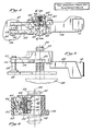
- the cartridge loading apparatus 18 is shown in detail in Figures 2 through 6.
- the head 14 is mounted at one end of a carriage 28.
- the other end of the carriage 28 terminates in a pair of parallel, elongated tines 30, 32.
- An elongated flexure bar 34 is pinned to the end of the carriage 28 and extends outwardly, parallel to the tines 30, 32.
- the bar 34 terminates in a hammer 36.
- the edge of the hammer 36 is slightly offset toward tine 32 compared to the edge of the tine 30.
- a stationary, cylindrical post 38 extends upwardly from the tape drive housing 26, and passes between the tines 30, 32.
- the tine 32 and hammer 36 are spaced a distance approximately equal to the diameter of the post 38 so that the hammer 36 and tine 32 engage the surface of the post 38.
- the tine 30 prevents the flexure 34 from being overstressed.
- a recess 40 is provided at a location proximate the midpoint of the carriage 28.
- the recess 40 extends from the bottom of the carriage 28 to the top of the carriage 28, and has a smooth, curved surface 42 which preferably is semi-circular in shape.
- the diameter of the semi-circular surface 42 is approximately equal to the outside diameter or major diameter of the threads 22 on the lead screw 20.
- the lead screw 20 extends through the recess 40 with sufficient clearance to allow the carriage 28 to slide relative to the lead screw 20.
- the partial nut 44 Positioned directly opposite the recess 40 is a partial nut 44.
- the partial nut 44 has a front 46 and a rear 48, with the front 46 facing towards the recess 40.
- the front 46 includes an arcuately curved surface 50.
- Two male thread segments 52 protrude outwardly from the curved surface 50.
- the thread segments 52 mate with the external threading 22 on the lead screw 20.
- the number of thread segments 52 may be greater than two, or as few as one.
- the partial nut 44 is secured to the carriage 28 by means of a support member 54.
- the support member 54 is attached to the partial nut at a location behind the arcuate surface 50, and is also attached to the carriage 28.
- the support member 54 is a thin, flexible, substantially planar metal plate. Referring to Figure 6, flexing the support member 54 allows the partial nut 44 to move in either direction along an axis 56, which is substantially normal to a longitudinal axis 58 of the lead screw 20.
- the width of the partial nut 44 is slightly less than the width of the recess 40, so that the partial nut 44 can advance forwardly into the recess 40.
- a cap 60 is attached to the carriage 28 opposite the recess 40.
- the cap 60 includes a surface 62 which is spaced directly behind the rear 48 of the partial nut 44.
- a coil spring 64 extends between the surface 62 on the cap 60 and the rear 48 of the partial nut 44.
- the spring 64 is oriented so that a longitudinal axis 56 of the spring 64 is coincident with the axis 56 along which the partial nut 44 is movable.
- the longitudinal axis 56 of the spring 64 is substantially normal to the surface 62 of the cap 60 and substantially normal to the longitudinal axis 58 of the lead screw 20.
- the spring 64 is held in position by a pin 66 which extends from the cap surface 62 and a pin 68 which extends from the rear 48 of the partial nut 44.
- the ends of the spring 64 surround the pins 66, 68.
- the cap 60, carriage 28, and a partial nut 44 are all fabricated from a molded polymer.
- the recess 40 guides the lead screw 20 relative to the carriage 28 so that the carriage 28 is movable in a direction which is substantially parallel to the longitudinal axis 58 of the lead screw 20.
- the spring 64 is compressed between the cap 60 and partial nut 44, so that a biasing force F is applied to the partial nut 44, forcing the partial nut 44 into engagement with the lead screw 20.
- the front 46 of the partial nut 44 engages the lead screw 20 so that the threading 22 on the lead screw 20 mates with the thread segments 52 on the partial nut 44. Motion of the partial nut 44 along the axis 56 in a direction toward the lead screw 20 is permitted by the flexibility of the support member 54.
- the support member 54 is designed so that any biasing force due to elastic deformation of the support member 54 upon flexing will be insignificant relative to the spring force F.
- the direction of the force F and the direction of motion of the partial nut 44 are both substantially parallel to the longitudinal axis 56 of the coil spring 64.
- the head 14 is moved to a desired position relative to the tape 16, by rotating stepping motor 24 a predetermined amount.
- the carriage 28 is prevented from rotating along with the lead screw 20 by the post 38, causing the thread segments 52 to advance along the lead screw threads 22.
- the carriage 28 slides along the lead screw 20 in a direction which is substantially parallel to the longitudinal axis 58 of the lead screw 20.
- the tine 30 prevents excessive displacement of the hammer 36.
- the flexure bar 34 causes the hammer 36 to provide a constant force against the post 38.
- any nominal clearance between the lead screw threading 22 and the thread segments 52 which may allow undesired motion of the carriage 28 is compensated for by applying a sufficient biasing force F to clamp the lead screw 20 between the recess 40 and the partial nut 44.
- a sufficient biasing force F to clamp the lead screw 20 between the recess 40 and the partial nut 44.
- the smooth surface 42 of the recess 40 allows the carriage 28 to slide relative to the lead screw 20.
- This arrangement enables a substantially more precise fit between the lead screw 20 and the carriage 28 than say, a full, annular nut (not shown) which must have a significant clearance with the lead screw 20 to prevent binding.
- the spring 64 It is critical that a consistent, predetermined force F is applied by the spring 64. If the force F is too low, too much clearance will be allowed between the lead screw 20 and the partial nut 44, resulting in an undesired change in orientation of the carriage 28 and the head 14. If the force F is too high, damage will occur to the thread segments 52, particularly if the partial nut 44 is formed from a molded polymer. In a preferred embodiment, the spring force F is approximately one pound or less.
- the spring 64 applies a consistent force F on the partial nut 44 in part due to the orientation of the spring 64, which causes the force F to be directed substantially parallel to the longitudinal axis 56 of the spring 64.
- the longitudinal axis 64 of the spring 56 is also parallel to the direction of motion of the partial nut 44. Additionally, the axis 56 passes through the cap surface 62, which is positioned directly behind the partial nut 44.
- the spring force F arises solely from compression of the spring 64, and thus is more predictable than if a torque or bending moment were applied to the spring 64.
- the precision capable with present head positioning apparatus 18 is evidenced by the fact that the apparatus 18 has been used successfully to record up to as many as 24 tracks of data on 1/4" wide tape 16. Further, since the space between the cap 60 and the partial nut 44 is relatively small, the head positioning apparatus 18 is compact, and can be less than 3 inches long by 1 inch wide. As will be apparent to those skilled in the art, the head positioning apparatus 18 may also be used in combination with other magnetic storage media, such as floppy disks (not shown).
Landscapes
- Moving Of Heads (AREA)
- Supporting Of Heads In Record-Carrier Devices (AREA)
Applications Claiming Priority (2)
| Application Number | Priority Date | Filing Date | Title |
|---|---|---|---|
| US06/849,146 US4747004A (en) | 1986-04-07 | 1986-04-07 | Magnetic head positioning apparatus |
| US849146 | 1986-04-07 |
Publications (2)
| Publication Number | Publication Date |
|---|---|
| EP0242091A2 true EP0242091A2 (fr) | 1987-10-21 |
| EP0242091A3 EP0242091A3 (fr) | 1989-05-31 |
Family
ID=25305173
Family Applications (1)
| Application Number | Title | Priority Date | Filing Date |
|---|---|---|---|
| EP87302920A Ceased EP0242091A3 (fr) | 1986-04-07 | 1987-04-03 | Dispositif de positionnement de tête magnétique |
Country Status (3)
| Country | Link |
|---|---|
| US (1) | US4747004A (fr) |
| EP (1) | EP0242091A3 (fr) |
| JP (1) | JPS6318509A (fr) |
Cited By (2)
| Publication number | Priority date | Publication date | Assignee | Title |
|---|---|---|---|---|
| EP0325166A3 (fr) * | 1988-01-21 | 1991-04-10 | Deutsche Thomson-Brandt GmbH | Disposition de roue porte-tête pour un enregistreur |
| EP0489088A4 (en) * | 1989-08-28 | 1993-03-03 | Wangtek, Inc. | Magnetic head positioner |
Families Citing this family (14)
| Publication number | Priority date | Publication date | Assignee | Title |
|---|---|---|---|---|
| US4833558A (en) * | 1986-04-25 | 1989-05-23 | Archive Corporation | Head positioning assembly |
| USRE33661E (en) * | 1986-04-25 | 1991-08-13 | Archive Corporation | Head positioning assembly |
| EP0317686A1 (fr) * | 1987-11-24 | 1989-05-31 | MANNESMANN Aktiengesellschaft | Dispositif de traitement de données utilisant des supports d'information magnétique |
| US4943877A (en) * | 1988-12-06 | 1990-07-24 | Colorado Memory Systems, Inc. | Fine head positioning system for a tape backup device |
| US4858047A (en) * | 1988-12-06 | 1989-08-15 | Colorado Memory Systems, Inc. | Fine head positioning system for a tape backup drive |
| US5105322A (en) * | 1990-06-29 | 1992-04-14 | Digital Equipment Corporation | Transverse positioner for read/write head |
| US5331490A (en) * | 1990-10-31 | 1994-07-19 | Hewlett-Packard Company | Tape head fine positioning system for a tape backup drive |
| US5251086A (en) * | 1991-10-11 | 1993-10-05 | Mpc Nakamichi Peripheral Corporation | Tape drive subassembly |
| US5812347A (en) * | 1991-12-10 | 1998-09-22 | Exabyte Acquisition Subsidiary Corp. | Positive drive head positioning apparatus |
| US5706149A (en) * | 1996-06-03 | 1998-01-06 | Tandberg Data Asa | Magnetic head positioning arrangement |
| US5973717A (en) * | 1998-04-15 | 1999-10-26 | Eastman Kodak Company | Adjustable lead screw for changing resolution and for station-to-station, machine-to-machine, or swath-to-swath corrections |
| US6061209A (en) * | 1998-04-29 | 2000-05-09 | Hewlett-Packard Company | Positioning system for a magnetic head for a tape drive |
| JP3686539B2 (ja) * | 1998-10-28 | 2005-08-24 | パイオニア株式会社 | ピックアップ送り機構 |
| US6697230B1 (en) | 2000-09-05 | 2004-02-24 | Seagate Removable Storage Solutions Llc | Three-point floating nut for a head positioner |
Family Cites Families (18)
| Publication number | Priority date | Publication date | Assignee | Title |
|---|---|---|---|---|
| DE2160363A1 (de) * | 1970-12-07 | 1972-07-27 | Pioneer Electronic Corp | Magnetbandaufzeichnungs- und Wiedergabegerät mit einer gestapelten Reihe unabhängiger Kassetten |
| US3833922A (en) * | 1973-03-12 | 1974-09-03 | Economy Co | Drive means for effecting pivotal vertical movement of a transducer head into operative position |
| US3858452A (en) * | 1973-07-09 | 1975-01-07 | Vemco Products Inc | Emergency release for screw drive operator traveler assembly |
| US4071866A (en) * | 1977-03-16 | 1978-01-31 | Sycor, Inc. | Disc recorder drive follower assembly |
| US4155269A (en) * | 1977-09-16 | 1979-05-22 | Clopay Corporation | Traveler and guide rail apparatus for screw drive closure operator |
| US4212043A (en) * | 1978-11-01 | 1980-07-08 | Ampex Corporation | Magnetic transducing |
| DE2918020A1 (de) * | 1979-05-04 | 1980-11-13 | Basf Ag | Positioniereinrichtung fuer einen magnetkopf eines magnetbandgeraetes |
| US4313143A (en) * | 1979-09-04 | 1982-01-26 | Minnesota Mining And Manufacturing Co. | Head positioning mechanism for data cartridge recorder |
| US4376961A (en) * | 1980-06-03 | 1983-03-15 | Fuji Electrochemical Co., Ltd. | Magnetic drum/head system for selectively generating recorded voice information |
| JPS576433A (en) * | 1980-06-13 | 1982-01-13 | Toshiba Corp | Magnetic recorder and reproducer |
| DE8023158U1 (de) * | 1980-08-30 | 1981-02-26 | Basf Ag, 6700 Ludwigshafen | Positioniervorrichtung fuer aufzeichnungs- und/oder abtastorgane in signal- aufzeichnungs-/wiedergabesystemen |
| US4514775A (en) * | 1982-05-03 | 1985-04-30 | Mfe Corporation | Streaming cassette tape transport |
| US4573091A (en) * | 1982-11-15 | 1986-02-25 | Cipher Data Products, Inc. | Cartridge tape drive |
| US4559571A (en) * | 1982-11-26 | 1985-12-17 | Data Electronics, Inc. | Tape cartridge drive with movable read/write head |
| DE3380538D1 (en) * | 1982-11-29 | 1989-10-12 | Tandberg Data | Arrangement for positioning a magnetic head on several tape tracks |
| DE3317720A1 (de) * | 1982-11-29 | 1984-11-22 | Tandberg Data A/S, Oslo | Magnetbandgeraet |
| US4608615A (en) * | 1984-04-30 | 1986-08-26 | Mark Zeavin | Half height data cartridge tape drive |
| US4609958A (en) * | 1984-05-29 | 1986-09-02 | Cipher Data Products, Inc. | Precision bearing for reciprocating a magnetic head |
-
1986
- 1986-04-07 US US06/849,146 patent/US4747004A/en not_active Expired - Lifetime
-
1987
- 1987-04-03 EP EP87302920A patent/EP0242091A3/fr not_active Ceased
- 1987-04-06 JP JP62084489A patent/JPS6318509A/ja active Pending
Cited By (2)
| Publication number | Priority date | Publication date | Assignee | Title |
|---|---|---|---|---|
| EP0325166A3 (fr) * | 1988-01-21 | 1991-04-10 | Deutsche Thomson-Brandt GmbH | Disposition de roue porte-tête pour un enregistreur |
| EP0489088A4 (en) * | 1989-08-28 | 1993-03-03 | Wangtek, Inc. | Magnetic head positioner |
Also Published As
| Publication number | Publication date |
|---|---|
| EP0242091A3 (fr) | 1989-05-31 |
| JPS6318509A (ja) | 1988-01-26 |
| US4747004A (en) | 1988-05-24 |
Similar Documents
| Publication | Publication Date | Title |
|---|---|---|
| US4747004A (en) | Magnetic head positioning apparatus | |
| CA2287897C (fr) | Systeme de bibliotheque a chargeur de donnees | |
| EP0710391B1 (fr) | Element de guidage rotatif de bord de bande magnetique | |
| EP0109154B1 (fr) | Entraînement de bande en cassette | |
| US3766327A (en) | Tape cassette holding and positioning unit | |
| EP1497830B1 (fr) | Receptacle pour support de stockage d'informations et procede d'utilisation associe | |
| US4556923A (en) | Tape cartridge drive with cartridge door opening mechanism | |
| JPS61221568A (ja) | ロ−タリ−アクチユエ−タおよび衝撃停止体アセンブリ | |
| US4559571A (en) | Tape cartridge drive with movable read/write head | |
| US4586095A (en) | Fail-safe locking mechanism for tape cartridge drive with movable read/write head | |
| US6259579B1 (en) | Picker indexing and multimedia cartridge referencing spring | |
| EP0084123A1 (fr) | Chariot à suspension en porte à faux pour transducteur | |
| EP0893797B1 (fr) | Système de positionnement de tête d'un entraînement de bande compact | |
| EP0062454B1 (fr) | Assemblage de têtes magnétiques pour disques magnétiques | |
| JP3658446B2 (ja) | カートリッジ | |
| US4766510A (en) | Carriage shift assembly for disc driving device | |
| CA2220304A1 (fr) | Mecanisme de chargement de tete pour unite de disques | |
| US7466511B2 (en) | Hand mechanism in a cartridge library apparatus being associated with a buffer mechanism to allow the hand mechanism to hold a cartridge even when the hand mechanism is not positioned at an optimal, normal position | |
| JP3745026B2 (ja) | カートリッジ操作装置のためのドアアセンブリ | |
| EP1094459B1 (fr) | Stockage et recherche de disque | |
| US5410794A (en) | Caddy and carrier tool for assembling a head arm stack | |
| WO1997026649A1 (fr) | Ensemble de positionnement de pistes dans un appareil d'enregistrement sur bandes magnetiques | |
| US5196975A (en) | Magnetic disk apparatus having head arm elastically supported on head carriage | |
| US5237474A (en) | Head cartridge apparatus having head supporting arm partially inserted into disk case through window formed therein | |
| JP3704042B2 (ja) | 可撓支持緩衝装置 |
Legal Events
| Date | Code | Title | Description |
|---|---|---|---|
| PUAI | Public reference made under article 153(3) epc to a published international application that has entered the european phase |
Free format text: ORIGINAL CODE: 0009012 |
|
| AK | Designated contracting states |
Kind code of ref document: A2 Designated state(s): DE FR GB IT SE |
|
| PUAL | Search report despatched |
Free format text: ORIGINAL CODE: 0009013 |
|
| AK | Designated contracting states |
Kind code of ref document: A3 Designated state(s): DE FR GB IT SE |
|
| 17P | Request for examination filed |
Effective date: 19891120 |
|
| 17Q | First examination report despatched |
Effective date: 19910325 |
|
| STAA | Information on the status of an ep patent application or granted ep patent |
Free format text: STATUS: THE APPLICATION HAS BEEN REFUSED |
|
| 18R | Application refused |
Effective date: 19940425 |
|
| RIN1 | Information on inventor provided before grant (corrected) |
Inventor name: VAN VALKENBURGH, JOHN C. Inventor name: KUKREJA, JAGMOHAN S. Inventor name: BUCKLAND, KURT A. |