EP0242058A1 - Lageerfassung - Google Patents
Lageerfassung Download PDFInfo
- Publication number
- EP0242058A1 EP0242058A1 EP87302250A EP87302250A EP0242058A1 EP 0242058 A1 EP0242058 A1 EP 0242058A1 EP 87302250 A EP87302250 A EP 87302250A EP 87302250 A EP87302250 A EP 87302250A EP 0242058 A1 EP0242058 A1 EP 0242058A1
- Authority
- EP
- European Patent Office
- Prior art keywords
- coil
- signal
- pick
- exciting
- coils
- Prior art date
- Legal status (The legal status is an assumption and is not a legal conclusion. Google has not performed a legal analysis and makes no representation as to the accuracy of the status listed.)
- Withdrawn
Links
- 238000006073 displacement reaction Methods 0.000 claims abstract description 5
- 239000006096 absorbing agent Substances 0.000 claims description 19
- 230000035939 shock Effects 0.000 claims description 19
- 239000000696 magnetic material Substances 0.000 claims description 2
- 239000012530 fluid Substances 0.000 description 5
- 230000005284 excitation Effects 0.000 description 4
- 238000001914 filtration Methods 0.000 description 3
- 230000003750 conditioning effect Effects 0.000 description 2
- 239000000428 dust Substances 0.000 description 2
- 239000004033 plastic Substances 0.000 description 2
- 229920003023 plastic Polymers 0.000 description 2
- 239000000725 suspension Substances 0.000 description 2
- 230000001360 synchronised effect Effects 0.000 description 2
- RYGMFSIKBFXOCR-UHFFFAOYSA-N Copper Chemical compound [Cu] RYGMFSIKBFXOCR-UHFFFAOYSA-N 0.000 description 1
- 238000006243 chemical reaction Methods 0.000 description 1
- 238000004140 cleaning Methods 0.000 description 1
- 229910052802 copper Inorganic materials 0.000 description 1
- 239000010949 copper Substances 0.000 description 1
- 238000000034 method Methods 0.000 description 1
- 238000005070 sampling Methods 0.000 description 1
Images

Classifications
-
- B—PERFORMING OPERATIONS; TRANSPORTING
- B60—VEHICLES IN GENERAL
- B60G—VEHICLE SUSPENSION ARRANGEMENTS
- B60G17/00—Resilient suspensions having means for adjusting the spring or vibration-damper characteristics, for regulating the distance between a supporting surface and a sprung part of vehicle or for locking suspension during use to meet varying vehicular or surface conditions, e.g. due to speed or load
- B60G17/015—Resilient suspensions having means for adjusting the spring or vibration-damper characteristics, for regulating the distance between a supporting surface and a sprung part of vehicle or for locking suspension during use to meet varying vehicular or surface conditions, e.g. due to speed or load the regulating means comprising electric or electronic elements
- B60G17/019—Resilient suspensions having means for adjusting the spring or vibration-damper characteristics, for regulating the distance between a supporting surface and a sprung part of vehicle or for locking suspension during use to meet varying vehicular or surface conditions, e.g. due to speed or load the regulating means comprising electric or electronic elements characterised by the type of sensor or the arrangement thereof
- B60G17/01933—Velocity, e.g. relative velocity-displacement sensors
-
- G—PHYSICS
- G01—MEASURING; TESTING
- G01D—MEASURING NOT SPECIALLY ADAPTED FOR A SPECIFIC VARIABLE; ARRANGEMENTS FOR MEASURING TWO OR MORE VARIABLES NOT COVERED IN A SINGLE OTHER SUBCLASS; TARIFF METERING APPARATUS; MEASURING OR TESTING NOT OTHERWISE PROVIDED FOR
- G01D5/00—Mechanical means for transferring the output of a sensing member; Means for converting the output of a sensing member to another variable where the form or nature of the sensing member does not constrain the means for converting; Transducers not specially adapted for a specific variable
- G01D5/12—Mechanical means for transferring the output of a sensing member; Means for converting the output of a sensing member to another variable where the form or nature of the sensing member does not constrain the means for converting; Transducers not specially adapted for a specific variable using electric or magnetic means
- G01D5/14—Mechanical means for transferring the output of a sensing member; Means for converting the output of a sensing member to another variable where the form or nature of the sensing member does not constrain the means for converting; Transducers not specially adapted for a specific variable using electric or magnetic means influencing the magnitude of a current or voltage
- G01D5/20—Mechanical means for transferring the output of a sensing member; Means for converting the output of a sensing member to another variable where the form or nature of the sensing member does not constrain the means for converting; Transducers not specially adapted for a specific variable using electric or magnetic means influencing the magnitude of a current or voltage by varying inductance, e.g. by a movable armature
- G01D5/204—Mechanical means for transferring the output of a sensing member; Means for converting the output of a sensing member to another variable where the form or nature of the sensing member does not constrain the means for converting; Transducers not specially adapted for a specific variable using electric or magnetic means influencing the magnitude of a current or voltage by varying inductance, e.g. by a movable armature by influencing the mutual induction between two or more coils
- G01D5/2046—Mechanical means for transferring the output of a sensing member; Means for converting the output of a sensing member to another variable where the form or nature of the sensing member does not constrain the means for converting; Transducers not specially adapted for a specific variable using electric or magnetic means influencing the magnitude of a current or voltage by varying inductance, e.g. by a movable armature by influencing the mutual induction between two or more coils by a movable ferromagnetic element, e.g. a core
-
- B—PERFORMING OPERATIONS; TRANSPORTING
- B60—VEHICLES IN GENERAL
- B60G—VEHICLE SUSPENSION ARRANGEMENTS
- B60G2204/00—Indexing codes related to suspensions per se or to auxiliary parts
- B60G2204/10—Mounting of suspension elements
- B60G2204/11—Mounting of sensors thereon
- B60G2204/112—Mounting of sensors thereon on dampers, e.g. fluid dampers
-
- B—PERFORMING OPERATIONS; TRANSPORTING
- B60—VEHICLES IN GENERAL
- B60G—VEHICLE SUSPENSION ARRANGEMENTS
- B60G2400/00—Indexing codes relating to detected, measured or calculated conditions or factors
- B60G2400/25—Stroke; Height; Displacement
- B60G2400/252—Stroke; Height; Displacement vertical
-
- B—PERFORMING OPERATIONS; TRANSPORTING
- B60—VEHICLES IN GENERAL
- B60G—VEHICLE SUSPENSION ARRANGEMENTS
- B60G2401/00—Indexing codes relating to the type of sensors based on the principle of their operation
- B60G2401/17—Magnetic/Electromagnetic
Definitions
- the present invention is concerned with a means of sensing the position of one member relative to another and in particular, but not exclusively, with a means of sensing the height of the spring mass of a vehicle relative to its unsprung mass in a vehicle suspension system.
- Such disadvantages in vehicle/microcomputer controls include, inter alia, the fact that (a) the resulting system is expensive and over-engineered, (b) filtering introduces time/phase lags which vary with frequency/rate of change, thereby making compensation difficult, (c) it is difficult to synchronise the A/D converter or microcomputer to the sinewave without overheads in hardware and software, and (d) response times are poor.
- a flat-topped pulse enables (a) the signal to be synchronised to a computer, allowing A/D readings to be taken at an exact and repeatable point, preferably in each half-cycle; and (b) only one A/D reading to be necessary each half cycle. Furthermore, since the signal is flat-topped, spike filtering does not cause either phase or amplitude errors at the time of A/D reading.
- the excitation coil is current driven to obviate temperature drift problems.
- the ramp signal may be provided using an integrated square wave input pulse provided, for example, by a microcomputer or digital I/O chip.
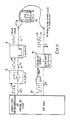
- the magnetic field generated by the exciting coil 2 is modified and causes an amplitude variation on the pick-up signal of Fig. 3.
- the output signal of Fig. 3 is rectified to provide a signal representative, for example, of a direct measure of vehicle load or an indication of overload or it may be used to trigger operation of solenoid controlled fluid valves to achieve automatic vehicle levelling.
- the excitation coil 2a is provided with a signal of ramp (sawtooth) waveform via a terminal 7.
- the signal V2 obtained from the pick-up coil 3a is essentially flat-topped. This means that it can be filtered without phase/time lag penalties and can be fed directly to an analogue to digital input or microcomputer (such as the unit 20) without the need for phase sensitive detectors etc.
- Temperature drift problems incurred in the traditional systems can be eliminated by current driving the excitation coil as described above and by ensuring that the copper resistance of all coils is small compared with resistance in the controller.
- the microcomputer Since the microcomputer controls the primary square wave (V o ), it needs to read the A/D input only once (just prior to toggling the square wave), each half cycle to obtain peak readings, i.e. it knows the optimum time to take an A/D reading. As mentioned above, it takes exactly one reading each half cycle, thereby saving sampling rates and processing time.
- the output signal (V3) which is almost a square wave, has settled for some time prior to the A/D reading.
Landscapes
- Physics & Mathematics (AREA)
- General Physics & Mathematics (AREA)
- Engineering & Computer Science (AREA)
- Mechanical Engineering (AREA)
- Measurement Of Length, Angles, Or The Like Using Electric Or Magnetic Means (AREA)
- Vehicle Body Suspensions (AREA)
Applications Claiming Priority (2)
| Application Number | Priority Date | Filing Date | Title |
|---|---|---|---|
| GB868609144A GB8609144D0 (en) | 1986-04-15 | 1986-04-15 | Position sensing |
| GB8609144 | 1986-04-15 |
Publications (1)
| Publication Number | Publication Date |
|---|---|
| EP0242058A1 true EP0242058A1 (de) | 1987-10-21 |
Family
ID=10596201
Family Applications (1)
| Application Number | Title | Priority Date | Filing Date |
|---|---|---|---|
| EP87302250A Withdrawn EP0242058A1 (de) | 1986-04-15 | 1987-03-17 | Lageerfassung |
Country Status (3)
| Country | Link |
|---|---|
| EP (1) | EP0242058A1 (de) |
| JP (1) | JPS62250301A (de) |
| GB (2) | GB8609144D0 (de) |
Cited By (1)
| Publication number | Priority date | Publication date | Assignee | Title |
|---|---|---|---|---|
| EP0697598A1 (de) | 1994-08-18 | 1996-02-21 | Mercedes-Benz Ag | Prüfeinrichtung für Fahrzeuge mit magnetfeldsensitivem Raddrehzahlsensor |
Families Citing this family (1)
| Publication number | Priority date | Publication date | Assignee | Title |
|---|---|---|---|---|
| GB2258308B (en) * | 1991-07-27 | 1994-09-14 | Univ Nottingham | Inductive coil movement gauge |
Citations (6)
| Publication number | Priority date | Publication date | Assignee | Title |
|---|---|---|---|---|
| GB2027207A (en) * | 1978-05-31 | 1980-02-13 | Armstrong Patents Co Ltd | Improvements in or relating to vehicle suspension systems |
| EP0039181A1 (de) * | 1980-04-26 | 1981-11-04 | LUCAS INDUSTRIES public limited company | Verschiebungsmesswandler und ihre Verwendung zum Abfühlen von Verschiebungen bei Fahrzeugaufhängungen |
| DE3241018A1 (de) * | 1981-11-10 | 1983-05-19 | Vacuumschmelze Gmbh, 6450 Hanau | Magnetisch arbeitender sensor |
| EP0128824A1 (de) * | 1983-06-08 | 1984-12-19 | Petercem S.A. | Verfahren und Vorrichtung zur Stellungsüberwachung eines im Innern eines dickwandigen Gehäuses angeordneten Schiebers |
| DE3329515A1 (de) * | 1983-08-16 | 1985-03-07 | Krohne Meßtechnik GmbH & Co KG, 4100 Duisburg | Elektrische schaltanordnung fuer einen magnetisch-induktiven messwertgeber |
| US4540188A (en) * | 1984-04-19 | 1985-09-10 | General Motors Corporation | Automatic vehicle level control |
Family Cites Families (1)
| Publication number | Priority date | Publication date | Assignee | Title |
|---|---|---|---|---|
| CH644698A5 (fr) * | 1981-09-04 | 1984-08-15 | Sentec Sa | Procede pour la mesure de la vitesse instantanee d'un mobile et application de ce procede pour la mesure de la variation instantanee de la vitesse de ce mobile. |
-
1986
- 1986-04-15 GB GB868609144A patent/GB8609144D0/en active Pending
-
1987
- 1987-03-17 EP EP87302250A patent/EP0242058A1/de not_active Withdrawn
- 1987-03-19 GB GB08706579A patent/GB2189325A/en not_active Withdrawn
- 1987-04-10 JP JP8965287A patent/JPS62250301A/ja active Pending
Patent Citations (6)
| Publication number | Priority date | Publication date | Assignee | Title |
|---|---|---|---|---|
| GB2027207A (en) * | 1978-05-31 | 1980-02-13 | Armstrong Patents Co Ltd | Improvements in or relating to vehicle suspension systems |
| EP0039181A1 (de) * | 1980-04-26 | 1981-11-04 | LUCAS INDUSTRIES public limited company | Verschiebungsmesswandler und ihre Verwendung zum Abfühlen von Verschiebungen bei Fahrzeugaufhängungen |
| DE3241018A1 (de) * | 1981-11-10 | 1983-05-19 | Vacuumschmelze Gmbh, 6450 Hanau | Magnetisch arbeitender sensor |
| EP0128824A1 (de) * | 1983-06-08 | 1984-12-19 | Petercem S.A. | Verfahren und Vorrichtung zur Stellungsüberwachung eines im Innern eines dickwandigen Gehäuses angeordneten Schiebers |
| DE3329515A1 (de) * | 1983-08-16 | 1985-03-07 | Krohne Meßtechnik GmbH & Co KG, 4100 Duisburg | Elektrische schaltanordnung fuer einen magnetisch-induktiven messwertgeber |
| US4540188A (en) * | 1984-04-19 | 1985-09-10 | General Motors Corporation | Automatic vehicle level control |
Cited By (4)
| Publication number | Priority date | Publication date | Assignee | Title |
|---|---|---|---|---|
| EP0697598A1 (de) | 1994-08-18 | 1996-02-21 | Mercedes-Benz Ag | Prüfeinrichtung für Fahrzeuge mit magnetfeldsensitivem Raddrehzahlsensor |
| DE4429311A1 (de) * | 1994-08-18 | 1996-02-22 | Daimler Benz Ag | Prüfeinrichtung für Fahrzeuge mit magnetfeldsensitivem Raddrehzahlsensor |
| US5594173A (en) * | 1994-08-18 | 1997-01-14 | Mercedes-Benz Ag | Test device for vehicles having a wheel rotation speed sensor which is sensitive to magnetic fields |
| DE4429311C2 (de) * | 1994-08-18 | 1998-05-20 | Daimler Benz Ag | Prüfeinrichtung für Fahrzeuge mit magnetfeldsensitivem Raddrehzahlsensor |
Also Published As
| Publication number | Publication date |
|---|---|
| JPS62250301A (ja) | 1987-10-31 |
| GB2189325A (en) | 1987-10-21 |
| GB8706579D0 (en) | 1987-04-23 |
| GB8609144D0 (en) | 1986-05-21 |
Similar Documents
| Publication | Publication Date | Title |
|---|---|---|
| US5095750A (en) | Accelerometer with pulse width modulation | |
| US5218308A (en) | Sensor for and method of detecting the position of a piston inside the cylinder of a dashpot | |
| GB2163260A (en) | Determining the travel of a piston relative to a cylinder | |
| EP0323094B1 (de) | Hochsensibler digitaler Geber für die Stellung der Radaufhängung eines Kraftfahrzeugs | |
| US6847874B2 (en) | Method for controlling the damping force of an adjustable damper in a motor vehicle | |
| EP0707195B1 (de) | Magnetischer Detektor der Bewegung eines Gegenstands | |
| EP0559265A1 (de) | Positionssensorsystem | |
| US6434451B1 (en) | Motion sensor for a motor vehicle | |
| GB2265010A (en) | Motion transducer | |
| CN1957230B (zh) | 位移传感器信号的误差校正方法 | |
| US5418468A (en) | Apparatus for determining the position and velocity of a moving object | |
| DE68926970D1 (de) | Linearer Weggeber, besonders verwendbar bei hydraulischen und pneumatischen Zylindern | |
| GB2189325A (en) | Improvements relating to position sensing | |
| EP0296808B1 (de) | Einrichtung zum Erfassen der Position und zugehörige hin- und hergehende Kolbenstange | |
| US20030115968A1 (en) | Capacitive microsystem for recording mechanical deformations, use and operating method | |
| US5668480A (en) | Variable-phase resistive transducer, and method of operating same | |
| US6501263B1 (en) | Rotary position sensor | |
| CN103162611A (zh) | 用于确定至交变磁场源的距离的测量系统和方法 | |
| US4856098A (en) | Inductance sensor and circuit arrangement for the detection of vehicle attitude | |
| GB2027207A (en) | Improvements in or relating to vehicle suspension systems | |
| CA2079394C (en) | Inertial sensor | |
| EP0936439A3 (de) | Induktiver Weg-Sensor | |
| US5635622A (en) | Method of compensating for gauge hysteresis | |
| EP1512937B1 (de) | Vorrichtung zur Erfassung der Position eines ersten Fahrzeugteils in Bezug auf ein zweites Fahrzeugteil, insbesondere zur Bestimmung der Nickposition eines Fahrzeuges und Fahrzeug mit einer derartigen Vorrichtung | |
| US5251728A (en) | Hydraulic vibration damper or shock absorber with electrical control connections and connector therefor |
Legal Events
| Date | Code | Title | Description |
|---|---|---|---|
| PUAI | Public reference made under article 153(3) epc to a published international application that has entered the european phase |
Free format text: ORIGINAL CODE: 0009012 |
|
| AK | Designated contracting states |
Kind code of ref document: A1 Designated state(s): DE ES FR IT NL |
|
| 17P | Request for examination filed |
Effective date: 19880420 |
|
| 17Q | First examination report despatched |
Effective date: 19891013 |
|
| STAA | Information on the status of an ep patent application or granted ep patent |
Free format text: STATUS: THE APPLICATION IS DEEMED TO BE WITHDRAWN |
|
| 18D | Application deemed to be withdrawn |
Effective date: 19900226 |
|
| RIN1 | Information on inventor provided before grant (corrected) |
Inventor name: WARDLE, MICHAEL JOHN |