EP0242034A2 - Filtre acousto-optique accordable - Google Patents
Filtre acousto-optique accordable Download PDFInfo
- Publication number
- EP0242034A2 EP0242034A2 EP87301817A EP87301817A EP0242034A2 EP 0242034 A2 EP0242034 A2 EP 0242034A2 EP 87301817 A EP87301817 A EP 87301817A EP 87301817 A EP87301817 A EP 87301817A EP 0242034 A2 EP0242034 A2 EP 0242034A2
- Authority
- EP
- European Patent Office
- Prior art keywords
- face
- crystal
- acousto
- optic
- acoustic
- Prior art date
- Legal status (The legal status is an assumption and is not a legal conclusion. Google has not performed a legal analysis and makes no representation as to the accuracy of the status listed.)
- Withdrawn
Links
Images

Classifications
-
- G—PHYSICS
- G02—OPTICS
- G02F—OPTICAL DEVICES OR ARRANGEMENTS FOR THE CONTROL OF LIGHT BY MODIFICATION OF THE OPTICAL PROPERTIES OF THE MEDIA OF THE ELEMENTS INVOLVED THEREIN; NON-LINEAR OPTICS; FREQUENCY-CHANGING OF LIGHT; OPTICAL LOGIC ELEMENTS; OPTICAL ANALOGUE/DIGITAL CONVERTERS
- G02F1/00—Devices or arrangements for the control of the intensity, colour, phase, polarisation or direction of light arriving from an independent light source, e.g. switching, gating or modulating; Non-linear optics
- G02F1/01—Devices or arrangements for the control of the intensity, colour, phase, polarisation or direction of light arriving from an independent light source, e.g. switching, gating or modulating; Non-linear optics for the control of the intensity, phase, polarisation or colour
- G02F1/11—Devices or arrangements for the control of the intensity, colour, phase, polarisation or direction of light arriving from an independent light source, e.g. switching, gating or modulating; Non-linear optics for the control of the intensity, phase, polarisation or colour based on acousto-optical elements, e.g. using variable diffraction by sound or like mechanical waves
- G02F1/116—Devices or arrangements for the control of the intensity, colour, phase, polarisation or direction of light arriving from an independent light source, e.g. switching, gating or modulating; Non-linear optics for the control of the intensity, phase, polarisation or colour based on acousto-optical elements, e.g. using variable diffraction by sound or like mechanical waves using an optically anisotropic medium, wherein the incident and the diffracted light waves have different polarizations, e.g. acousto-optic tunable filter [AOTF]
Definitions
- This invention relates to acousto-optic tunable filters.
- the improved acousto-optic tunable filter of this invention has a modified configuration which provides minimum resolution degradation when the acousto-optic tunable filter is operated in a wavelength scan mode.
- acousto-optic filter refers to the fact that in certain birefringent optic materials, a light beam propagating as an e-ray or an o-ray, can under certain conditions, be converted into an o-ray or an e-ray, respectively, by interaction with, and diffraction from an acoustic wave propagating in the same medium. Both conversions occur simultaneously.
- This phenomenon has been utilized in producing narrow band optical filters in which the peak transmission wavelength can be selected by properly choosing the frequency of the acoustic wave.
- Such filters have typically operated in the visible spectral region using collinearly propagating acoustic and light beams in selected oxide materials. It is also known that the acoustic wave can be launched into the acoustic medium non-collinearly with the light beam in order to achieve the same acousto-optic narrow band filtering.
- Acousto-optic tunable filters have been utilized in analytical devices which can be used to analyze reaction products of a wide variety of industrial processes. Acoustic-optic tunable filters can also be used in on-line multi-function analyzers which are needed in the chemical and petroleum industries to function as process analyzers to facilitate process control systems.
- An example of a system incorporating an acousto-optic device is taught in the specification of U. S. Patent NO. 4,490,845.
- the aforementioned analysis system is set forth in greater detail in, "Automated Acousto-Optic Tunable Filter (AOTF) Infrared Analyzer", Proceedings of SPIE, International Society of Optical Engineering, Vol. 268, Pages 160-166, which is incorporated herein by reference.
- An acousto-optic tunable filter is a device which may serve the function of a spectrometer or monochromator.
- the AOTF is a device in which sound waves interact with light inside of a crystal of a particular type and orientation. The interaction is specific in that the sound waves of a given wavelength, produced by exciting an attached transducer with RF energy of a given frequency, interact with light of a given wavelength. If broadband light is incident upon an AOTF, a narrow wavelength interval of light may be selectively interacted with or diffracted by exciting the transducer with the appropriate frequency.
- acoustic waves are launched from a transducer mounted on one face of the crystal.
- Acoustic waves travel through the crystal and strike the face opposite the transducer.
- fixed RF drive frequency i.e., a fixed sound wavelength
- reflection of sound from the side of the crystal opposite the transducer present no problem in the functioning of the AOTF.
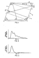
- the reflected wave is equally able to produce diffraction of the incident light. Since the reflected wave is at the same wavelength as the sound waves generated at the transducer, the diffracted light from the reflections is at the identical wavelength, so that no loss of resolution or wavelength spread occurs.
- acousto-absorber be attached to the crystal face opposite the transducer face to attenuate sound reflection.
- acousto-absorbers are difficult to fabricate, they are not perfect and some sound is invariably reflected, leading to a degradation in crystal performance.
- An object is to provide a configuration for an acousto-optic tunable filter which provides a minimum of resolution degradation when operated in a wavelength scan mode.
- Another object is to provide an acousto-optic tunable filter which is ideally suited for use in a frequency sweep RF drive mode of operation.
- Yet another object is to provide an AOTF with a modified configuration that facilitates an increased duty cycle when used in an acousto-optic tunable filter system.
- the present invention includes an acousto-optical tunable filter of the type in which an optically aligned acousto-optic crystal (13) has an optical input face (15) and an optical output face (19) through which a light is passed at a predetermined angle relative to the crystal optic axis, an acoustic transducer means (21) adapted to be coupled to an RF energy source is mounted onto a first face of the acousto-optic crystal in order to launch acoustic waves into the crystal, a selected bandwidth portion of the light being passed through the crystal is distinguished through diffraction from the remaining light as a function of the launched acoustic wave frequency, characterized in that a second face (23) of the acoustic-optic crystal opposite said first face on which the acoustic transducer means is mounted, which second face is non-parallel relative to said first face, so that acoustic waves launched into the acoustic crystal are reflected by said non-paralle
- a selected narrow bandwidth portion of the light being passed to the crystal is distinguished through diffraction from the remaining light as a function of the launched acoustic wave frequency.
- the improvement to this AOTF comprises a second face of the acousto-optic crystal opposite the first face on which the acoustic transducer is mounted, which second face is non-parallel relative to the first face.
- the RF energy source coupled to the acoustic transducer includes means for applying a frequency sweep RF drive to the acoustic transducer whereby a wavelength sweep of diffracted light is the output of the light passing through the acousto-optic crystal.
- the non-parallel second face of the acousto-optic crystal opposite the face on which the transducer is mounted has between about an 8° to 30° deviation relative to the first face. The selected angle should be large enough to destroy the phase-match relationship between light and sound waves, but not so large as to interfere with the optical aperture of the crystal.
- the invention provides an improved acousto-optic tunable filter (AOTF) which suffers a minimum of resolution degradation when operated in a wavelength scan mode.
- AOTF acousto-optic tunable filter
- the crystal face opposite the transducer is parallel to the transducer face.
- reflections of found traveling through the crystal strike the face opposite the transducer and tend to broaden the wavelength response. Accordingly, the elimination of this phenomenon is desirable.
- the present invention accomplishes this by changing the direction of reflection of the acoustic waves introduced into the optic crystal.
- Figure 1 shows an acousto-optic tunable filter 11 including a crystal 13 having an optical input face 15, an optical output face 17, a first face 19 on which a transducer 21 is bonded and a second opposed face 23.
- the reference character 25 the second face of an acousto-optical tunable filter configured according to conventional techniques known in the art.
- the face 25 is parallel with the first face 19 onto which the transducer 21 is bonded.
- the acoustic transducer 21 is mated to one of the opposed side surfaces of the crystal 13 and consists typically of an X-cut lithium niobate crystal plate which is attached to the acousto-optic crystal with an indium metal bond.
- a conductive electrode pattern is disposed on both sides of the lithium niobate transducer.
- the optical input face 15 of the crystal 13 is cut so as to be normal to the incident light 27.
- the output face 17 is then cut so as to be normal to the diffracted light output of the crystal 13.
- acoustic waves launched by the transducer 21 into the crystal 13 interact with light passing through the crystal. These sound waves are reflected from the second face 23 of the crystal 13. These reflections can be made to lose their interaction properties with the light passing through the crystal through the redirecting of the reflected light by means of a non-parallel face 23 opposite the transducer 21.
- the non-parallel face 23 directs the reflected sound wave to prevent diffraction from occurring.
- the degree of deviation from parallel of the non-parallel face 23 is based at least in part on the design of the AOTF, i.e., the angle with which the incident light enters the crystal relative to the C axis of the AOTF crystal.
- the angle of the incident light relative to the C axis is 35°.
- an angle between a minimum of about 7° to a maximum of about 30°, preferably about 10° is sufficient to destroy the interaction.
- 10° deviation from parallel relative to the transducer face 19 is sufficient to destroy the interaction.
- the angle should be no less than about 7° and no larger than about 30°. These limits will vary for other design acousto-optic devices with the minimum angle required getting larger for designs over 35° and the maximum angle required getting smaller for designs over 35°. For designs of less than 35°, the minimum angle becomes smaller and the maximum angle become larger. In other words, the angle should be selected so as to be large enough to destroy the phase-match relationship between the light and sound waves, but small enough so as not to adversely effect the optical aperture. In the example described and illustrated herein, these angles are between about 7° to 30°, respectively. As a result of the new configuration taught herein, the AOTF as shown in Figure 1 can be utilized in a frequency scan operation with no loss in resolution.
- FIG 4 there is illustrated a schematic representation of an acousto-optic tunable filter infrared analyzer system incorporating the features of this invention.
- the system is generally indicated by the reference character 31 and is configured from several subsystems and components including an acousto-optic tunable filter 11.
- the analyzer system 31 can be viewed as having two major subsystems, an optic subsystem 33 and an electronic subsystem 35.
- the optical system 33 of the analyzer system 31 is essentially an infrared solid state spectrometer which has been designed to permit operation over a relatively wide spectral range.
- An infrared radiation source 37 such as a Nernst glower, is used as the primary source of broadband infrared radiation for the system.
- a portion of the output infrared radiation from the source 37 is collected and collimated by a mirror 39.
- the collimated beam from the mirror 39 is passed through the AOTF 13 in which a narrow bandwidth portion of the radiation is selected and distinguished form the remaining infrared radiation as shown in the dashed lines of Figure 4.
- a detector means 41 is aligned so as to collect the spatially separated narrow band interaction radiation output from the AOTF 13 after it passes through an environment of interest generally indicated by the reference character 43 such as, for example, an industrial process stack.
- the detector means 41 provides an output via line 45 for processing in a manner to be described below.
- the environment of interest in the particular application illustrated herein is a stack gas of, for example, an industrial processing plant or a utility, and is generally indicated by the reference character 43.
- the stack 43 includes opposed sidewalls 47 and 49.
- the detector means 41 and the source means containing the AOTF 11 are placed on opposite sides of the stack 43.
- the angular displacement of the narrow band interacted radiation is adequate to separate it spatially from the broadband non-interacted radiation at the detector.
- the analog output signal from the infrared detector means 41 is provided via line 45 to an amplifier 51 and then to an analog-to-digital converter 53 with the resultant digital signal applied to a microcomputer 55.
- the electrical system 17 interfaces with the optical system 15 at the acousto-optic tunable filter 11 via the transducer 21 which is connected to the RF amplifier 57.
- a selected frequency RF drive power or a scanning RF frequency drive power is applied via the transducer in order to launch acoustic waves into the crystal 13. In this way, optically filtered infrared radiation can be detected and utilized by the microcomputer to determine the absorption resulting from the presence of selected gases in the gas stack 25.
- the microcomputer 55 typically has a video output means 59 associated therewith for visual display of detected signals, as well as memory means such as a disc drive 61 and a printer 63.
- the memory means 61 stores the control and operation signal for the system.
- the microcomputer 55 through an appropriate interface means 65, when supplied with control signals from the memory means 61, controls the output frequency and amplitude from a frequency synthesizer 67 which is connected by a gate means 69 to the RF amplifier 57 for controlled operation.
- the gate 69 can be utilized in conjunction with a pulse inhibit circuit means 71 in order to provide assurance that the RF power duty cycle is limited to a load level which does not overheat the crystal 13.
- the system described above is thus capable of operating in several modes including a rapidly tunable narrow band infrared filter mode, a solid state optical chopper mode and an infrared filter operated in a sweep mode with an increase in resolution of the optical bandwidth.
Landscapes
- Physics & Mathematics (AREA)
- Nonlinear Science (AREA)
- General Physics & Mathematics (AREA)
- Optics & Photonics (AREA)
- Optical Modulation, Optical Deflection, Nonlinear Optics, Optical Demodulation, Optical Logic Elements (AREA)
- Spectrometry And Color Measurement (AREA)
Applications Claiming Priority (2)
| Application Number | Priority Date | Filing Date | Title |
|---|---|---|---|
| US83711986A | 1986-03-07 | 1986-03-07 | |
| US837119 | 1986-03-07 |
Publications (2)
| Publication Number | Publication Date |
|---|---|
| EP0242034A2 true EP0242034A2 (fr) | 1987-10-21 |
| EP0242034A3 EP0242034A3 (fr) | 1989-07-12 |
Family
ID=25273568
Family Applications (1)
| Application Number | Title | Priority Date | Filing Date |
|---|---|---|---|
| EP87301817A Withdrawn EP0242034A3 (fr) | 1986-03-07 | 1987-03-02 | Filtre acousto-optique accordable |
Country Status (4)
| Country | Link |
|---|---|
| EP (1) | EP0242034A3 (fr) |
| JP (1) | JPS62229217A (fr) |
| CN (1) | CN87101685A (fr) |
| CA (1) | CA1285060C (fr) |
Family Cites Families (6)
| Publication number | Priority date | Publication date | Assignee | Title |
|---|---|---|---|---|
| JPS5431816B2 (fr) * | 1973-12-14 | 1979-10-09 | ||
| US4081216A (en) * | 1976-06-25 | 1978-03-28 | The United States Of America As Represented By The Department Of Health, Education And Welfare | Ultrasonic transducer calibration |
| JPS5494089A (en) * | 1978-01-06 | 1979-07-25 | Matsushita Electric Ind Co Ltd | Color sample producer |
| US4342502A (en) * | 1980-06-12 | 1982-08-03 | Itek Corporation | Transverse tunable acousto-optic filter |
| US4505550A (en) * | 1982-02-02 | 1985-03-19 | Westinghouse Electric Corp. | Infrared acousto-optic tunable filter |
| JPS5919922A (ja) * | 1982-07-27 | 1984-02-01 | Hoya Corp | 音響光学変調素子 |
-
1987
- 1987-02-20 CA CA000530257A patent/CA1285060C/fr not_active Expired - Lifetime
- 1987-03-02 EP EP87301817A patent/EP0242034A3/fr not_active Withdrawn
- 1987-03-04 JP JP4987987A patent/JPS62229217A/ja active Pending
- 1987-03-05 CN CN198787101685A patent/CN87101685A/zh active Pending
Also Published As
| Publication number | Publication date |
|---|---|
| CN87101685A (zh) | 1987-12-02 |
| CA1285060C (fr) | 1991-06-18 |
| EP0242034A3 (fr) | 1989-07-12 |
| JPS62229217A (ja) | 1987-10-08 |
Similar Documents
| Publication | Publication Date | Title |
|---|---|---|
| US4505550A (en) | Infrared acousto-optic tunable filter | |
| US4490845A (en) | Automated acousto-optic infrared analyzer system | |
| US4652756A (en) | Automated acousto-optic infra-red analyzer system for monitoring stack emissions | |
| US4639092A (en) | Acousto-optic dispersive light filter | |
| US4602342A (en) | Acousto-optic tunable filter | |
| Tran | Acousto-optic devices | |
| Chang | Acousto-optic tunable filters | |
| US4653869A (en) | Acousto-optic dispersive light filter | |
| CA1278196C (fr) | Systeme de tele-analyse chimique | |
| EP0250070B1 (fr) | Méthode optique d'analyse et appareil à accès rapide programmable à longueur d'onde accidentelle | |
| CA1194972A (fr) | Processeur acousto-optique a decoupage en voies | |
| US4999013A (en) | Controllable interferometer | |
| US5909304A (en) | Acousto-optic tunable filter based on isotropic acousto-optic diffraction using phased array transducers | |
| US3644015A (en) | Acousto-optic band reject light filter and apparatus using same | |
| US4342502A (en) | Transverse tunable acousto-optic filter | |
| EP0242034A2 (fr) | Filtre acousto-optique accordable | |
| Shipp et al. | Performance characteristics of an electronically tunable acousto‐optic filter for fast scanning spectrophotometry | |
| CA1240868A (fr) | Deflecteur de rayons acousto-optiques | |
| US4685772A (en) | Tunable acousto-optic filter with improved spectral resolution and increased aperture | |
| US4940316A (en) | Apparatus and method for increasing the efficiency of an acousto optic diffractive device | |
| CA1261955A (fr) | Filtre accordable acousto-optique a deux voies acoustiques | |
| Feigley et al. | Monitoring of chemical degradation in propellants using AOTF spectrometer | |
| Chang | Acousto-optic tunable filter | |
| US6433916B1 (en) | Octave spectra acousto-optic tunable filter | |
| US4735490A (en) | Electro-optical light modulator having a reduced piezo-optical effect |
Legal Events
| Date | Code | Title | Description |
|---|---|---|---|
| PUAI | Public reference made under article 153(3) epc to a published international application that has entered the european phase |
Free format text: ORIGINAL CODE: 0009012 |
|
| AK | Designated contracting states |
Kind code of ref document: A2 Designated state(s): DE FR GB IT |
|
| PUAL | Search report despatched |
Free format text: ORIGINAL CODE: 0009013 |
|
| AK | Designated contracting states |
Kind code of ref document: A3 Designated state(s): DE FR GB IT |
|
| 17P | Request for examination filed |
Effective date: 19900103 |
|
| STAA | Information on the status of an ep patent application or granted ep patent |
Free format text: STATUS: THE APPLICATION IS DEEMED TO BE WITHDRAWN |
|
| 18D | Application deemed to be withdrawn |
Effective date: 19901003 |
|
| RIN1 | Information on inventor provided before grant (corrected) |
Inventor name: RYAN, FREDERICK MERK Inventor name: GOTTLEIB, MILTON |