EP0241916B1 - An arrangement for the raising of packing container blanks - Google Patents
An arrangement for the raising of packing container blanks Download PDFInfo
- Publication number
- EP0241916B1 EP0241916B1 EP87105530A EP87105530A EP0241916B1 EP 0241916 B1 EP0241916 B1 EP 0241916B1 EP 87105530 A EP87105530 A EP 87105530A EP 87105530 A EP87105530 A EP 87105530A EP 0241916 B1 EP0241916 B1 EP 0241916B1
- Authority
- EP
- European Patent Office
- Prior art keywords
- arrangement
- container
- blank
- container blank
- suction heads
- Prior art date
- Legal status (The legal status is an assumption and is not a legal conclusion. Google has not performed a legal analysis and makes no representation as to the accuracy of the status listed.)
- Expired - Lifetime
Links
Images


Classifications
-
- B—PERFORMING OPERATIONS; TRANSPORTING
- B65—CONVEYING; PACKING; STORING; HANDLING THIN OR FILAMENTARY MATERIAL
- B65B—MACHINES, APPARATUS OR DEVICES FOR, OR METHODS OF, PACKAGING ARTICLES OR MATERIALS; UNPACKING
- B65B43/00—Forming, feeding, opening or setting-up containers or receptacles in association with packaging
- B65B43/26—Opening or distending bags; Opening, erecting, or setting-up boxes, cartons, or carton blanks
- B65B43/265—Opening, erecting or setting-up boxes, cartons or carton blanks
-
- B—PERFORMING OPERATIONS; TRANSPORTING
- B65—CONVEYING; PACKING; STORING; HANDLING THIN OR FILAMENTARY MATERIAL
- B65B—MACHINES, APPARATUS OR DEVICES FOR, OR METHODS OF, PACKAGING ARTICLES OR MATERIALS; UNPACKING
- B65B43/00—Forming, feeding, opening or setting-up containers or receptacles in association with packaging
- B65B43/12—Feeding flexible bags or carton blanks in flat or collapsed state; Feeding flat bags connected to form a series or chain
- B65B43/14—Feeding individual bags or carton blanks from piles or magazines
- B65B43/20—Feeding individual bags or carton blanks from piles or magazines by reciprocating or oscillating pushers
- B65B43/205—Feeding individual bags or carton blanks from piles or magazines by reciprocating or oscillating pushers specially adapted for carton blanks
-
- B—PERFORMING OPERATIONS; TRANSPORTING
- B31—MAKING ARTICLES OF PAPER, CARDBOARD OR MATERIAL WORKED IN A MANNER ANALOGOUS TO PAPER; WORKING PAPER, CARDBOARD OR MATERIAL WORKED IN A MANNER ANALOGOUS TO PAPER
- B31B—MAKING CONTAINERS OF PAPER, CARDBOARD OR MATERIAL WORKED IN A MANNER ANALOGOUS TO PAPER
- B31B2100/00—Rigid or semi-rigid containers made by folding single-piece sheets, blanks or webs
-
- B—PERFORMING OPERATIONS; TRANSPORTING
- B31—MAKING ARTICLES OF PAPER, CARDBOARD OR MATERIAL WORKED IN A MANNER ANALOGOUS TO PAPER; WORKING PAPER, CARDBOARD OR MATERIAL WORKED IN A MANNER ANALOGOUS TO PAPER
- B31B—MAKING CONTAINERS OF PAPER, CARDBOARD OR MATERIAL WORKED IN A MANNER ANALOGOUS TO PAPER
- B31B2120/00—Construction of rigid or semi-rigid containers
- B31B2120/30—Construction of rigid or semi-rigid containers collapsible; temporarily collapsed during manufacturing
-
- B—PERFORMING OPERATIONS; TRANSPORTING
- B31—MAKING ARTICLES OF PAPER, CARDBOARD OR MATERIAL WORKED IN A MANNER ANALOGOUS TO PAPER; WORKING PAPER, CARDBOARD OR MATERIAL WORKED IN A MANNER ANALOGOUS TO PAPER
- B31B—MAKING CONTAINERS OF PAPER, CARDBOARD OR MATERIAL WORKED IN A MANNER ANALOGOUS TO PAPER
- B31B50/00—Making rigid or semi-rigid containers, e.g. boxes or cartons
- B31B50/02—Feeding or positioning sheets, blanks or webs
- B31B50/04—Feeding sheets or blanks
- B31B50/06—Feeding sheets or blanks from stacks
- B31B50/062—Feeding sheets or blanks from stacks from the underside of a magazine
- B31B50/064—Feeding sheets or blanks from stacks from the underside of a magazine by being moved in the plane they are lying in
-
- B—PERFORMING OPERATIONS; TRANSPORTING
- B31—MAKING ARTICLES OF PAPER, CARDBOARD OR MATERIAL WORKED IN A MANNER ANALOGOUS TO PAPER; WORKING PAPER, CARDBOARD OR MATERIAL WORKED IN A MANNER ANALOGOUS TO PAPER
- B31B—MAKING CONTAINERS OF PAPER, CARDBOARD OR MATERIAL WORKED IN A MANNER ANALOGOUS TO PAPER
- B31B50/00—Making rigid or semi-rigid containers, e.g. boxes or cartons
- B31B50/74—Auxiliary operations
- B31B50/76—Opening and distending flattened articles
- B31B50/80—Pneumatically
Definitions
- Suction heads are attached on a bar which is a means for axially moving a guiding means for an arm of another suction head so that the flat container blank can be raised from the flattened form into a form of a rhombus.
- the bar also serves for moving the container blank into a delivery position between driving means. During this movement the blank strikes a wall so that the wall assists to bring the container blank from the rhombus form into a rectangular form.
- EP-A-0 011 965 describes another arrangement for raising of flattened tubular packing blanks.
- suction heads suction a blank out of a magazine which blank is axially moved into an intermediate position. In this position suction heads attach themselves to the blank from opposite sides. While one pair of suction heads are stationery members the suction heads on the other side of the blank can be moved so that the flattened blank can be raised until one edge of the blank strikes against a guide means before the blank reaches a delivery position.
- the magazine 3 is of elongated shape with a width corresponding to the length of the container blanks 2, and preferably is oriented so that its longitudinal direction is parallel with the direction of movement of the conveyoor arrangement 4.
- the magazine 3, moreover, has a base plate 8 and longitudinal side supports 9 for the correct alignment of a stack of container blanks 2 lying compactly on the base plate 8.
- the stack of container blanks 2 lying in the magazine 3 is pressed continuously with a certain force against a driving plate 10 serving as an output device at the feeding-out end of the magazine 3, in order to ensure that one packing container blank 2 is ready at all times at the outlet end of the magazine 3 for transfer to the conveyor arrangement 4.
- This action of the packing container blanks 2 upon the outlet end of the magazine 3 is not shown in the Figures, but may consist of some conventional arrangement, e.g. a pressure plate subjected to spring or weight action at the other end of the magazine 3.
- the driving plate 10 serving as an output device at the feeding-out end of the magazine 3 has a lateral surface substantially plane against the container blanks 2 with a slightly projecting edge 11, arranged parallel with the horizontal container blanks 2, whose height substantially corresponds to, or is slightly less than, the thickness of a flattened container blank 2.
- the driving plate 10 is connected at the bottom to a driving rod 12 driven by a motor (not shown), and at the top is joined to two connecting arms of driven elements 14 in hinged connection 13 with each other. Each of the connecting arms is joined at the top to a substantially horizontal arm l5 whose length coincides with, or even slightly exceeds, the length of a container blank 2.
- the driving plate 10 is drivable with the help of the driving shaft 12 in a reciprocating vertical movement between a lower and an upper position which in the example shown correspond to the projecting feed edge 11 on the driving plate 10 mentioned earlier being in its lower position directly below the bottom edge of the container blank 2 lying outermost in the magazin 3, whilst in the upper position the feed edge is level with, or just above, the top edge of the remaining container blanks 2.
Abstract
Description
- The invention relates to an arrangement for raising of flattened tubular packing container blanks in accordance with the first part of claim 1.
- Such arrangements are described in DE-A-3 010 891. Suction heads are attached on a bar which is a means for axially moving a guiding means for an arm of another suction head so that the flat container blank can be raised from the flattened form into a form of a rhombus. The bar also serves for moving the container blank into a delivery position between driving means. During this movement the blank strikes a wall so that the wall assists to bring the container blank from the rhombus form into a rectangular form.
- Furthermore, EP-A-0 011 965 describes another arrangement for raising of flattened tubular packing blanks. At first, suction heads suction a blank out of a magazine which blank is axially moved into an intermediate position. In this position suction heads attach themselves to the blank from opposite sides. While one pair of suction heads are stationery members the suction heads on the other side of the blank can be moved so that the flattened blank can be raised until one edge of the blank strikes against a guide means before the blank reaches a delivery position.
- Furthermore, US-A-3 783 752 describes two separate drive systems providing temporary interaction for blank raising.
- All of these arrangements are used in the field of the packaging industry where certain types of liquid contents, like milk, are packed into consumer packages of the non-returnable type.
- It is an object of the invention to find an arrangement by means of which it is possible to provide a more reliable and quicker raising of the blanks by relatively simple means.
- The invention is characterized in claim 1 and special embodiments are claimed in sub-claims and described in connection with the drawings. In accordance with the invention it is advisable to fold out the container blank by the suction heads into a substantially triangular form according to which the two side panels which are on opposite sides of the flattened blanks and which are attached by the oppositely arranged suction heads are on the same side while the other side panels which are free of suction heads form the other two sides to the triangle. From this "over-folded position" the container blank can easily and automatically reach a substantially rectangular form as soon as one of the suction heads provides no more suction to the respective side panel of the container blank while the other suction head still suctions the respective side panel.
- One embodiment of the invention is shown on the drawings:
- Figure 1 shows a perspective view of an arrangement in accordance with the invention for the transfer and raising of flattened, tubular packing container blanks from a magazine to a movable conveyor arrangement for the feeding on of raised blanks into a packing machine.
- Fig. 2a-2d illustrate schematically the principle of operation of the arrangement shown in Fig.1, and
- Fig.3 shows an example of a conventional packing container blank in flattened condition for raising with the help of the arrangement shown.
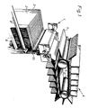
- In Fig.l is thus shown an arrangement 1 in accordance with the invention for the transfer and raising of flattened, tubular
packing container blanks 2 from amagazine 3 to a conveyor arrangement 4 for the feeding on of raisedblanks 2 into a packing machine, not shown, which from raised packing container blanks manufactures filled and closed packing containers. The conveyor arrangement 4 has its receiving end, located to the left in the Figure, placed substantially straight above the feeding-out end of themagazine 3 and comprises, for example,conveyor belts 6 drivenround rollers 5 in the direction of feed, with driver means 7 arranged so that the space between them corresponds to the shape of a raised container blank 2 of rectangular cross-section. - The
magazine 3 is of elongated shape with a width corresponding to the length of thecontainer blanks 2, and preferably is oriented so that its longitudinal direction is parallel with the direction of movement of the conveyoor arrangement 4. Themagazine 3, moreover, has abase plate 8 and longitudinal side supports 9 for the correct alignment of a stack ofcontainer blanks 2 lying compactly on thebase plate 8. The stack ofcontainer blanks 2 lying in themagazine 3 is pressed continuously with a certain force against adriving plate 10 serving as an output device at the feeding-out end of themagazine 3, in order to ensure that one packing container blank 2 is ready at all times at the outlet end of themagazine 3 for transfer to the conveyor arrangement 4. This action of the packing container blanks 2 upon the outlet end of themagazine 3 is not shown in the Figures, but may consist of some conventional arrangement, e.g. a pressure plate subjected to spring or weight action at the other end of themagazine 3. - The
driving plate 10 serving as an output device at the feeding-out end of themagazine 3 has a lateral surface substantially plane against thecontainer blanks 2 with a slightly projectingedge 11, arranged parallel with thehorizontal container blanks 2, whose height substantially corresponds to, or is slightly less than, the thickness of a flattened container blank 2. Thedriving plate 10 is connected at the bottom to adriving rod 12 driven by a motor (not shown), and at the top is joined to two connecting arms of drivenelements 14 inhinged connection 13 with each other. Each of the connecting arms is joined at the top to a substantially horizontal arm l5 whose length coincides with, or even slightly exceeds, the length of a container blank 2. Thearms 15 are suspended with their ends in guide means 16 in the form of tracks located right opposite each other onsupport plates 17 arranged at the ends of the arms.Thearms 15 are provided,moreover,with suction elements 18 in the form ofsuction heads arms 15 which via connecting ducts l9a and l9b can be joined either to a common, or each to its own, vacuum source (not shown). It is important in this context in accordance with the invention that the connection of thesuction heads respective suction heads - The
driving plate 10 is drivable with the help of thedriving shaft 12 in a reciprocating vertical movement between a lower and an upper position which in the example shown correspond to the projectingfeed edge 11 on thedriving plate 10 mentioned earlier being in its lower position directly below the bottom edge of the container blank 2 lying outermost in themagazin 3, whilst in the upper position the feed edge is level with, or just above, the top edge of the remaining container blanks 2. In the lower position so defined thearms 15 are in such a position that the suction heads l8a and l8b, respectively, find themselves right opposite each other, whilst in the upper position , owing to the upwards movement of the arms controlled away from each other along thetracks 16 in thesupport plates 17,thesuction heads - In the following the function of the arrangement shown will be described with reference to Fig. 2a-2d which schematically illustrate the course of its function during a working cycle, but in order to make this description clear, a brief description of a packing container blank 2 will be given first with special reference to Figure 3 which shows such a container blank 2 in flattened condition to be raised to a shape of substantially square cross-section with the help of the aforesaid arrangement in accordance with the present invention.
- The packing container blank 2, as mentioned earlier, is conventional and may be manufactured, for example, from a flexible but form-stable laminated material, e.g. a packing laminate which comprises layers of paper and plastics. After the laminate has been cut to the desired outer contour and provided with crease lines facilitating the fold-forming, two longitudinal edges are sealed together so that the laminate is converted to a tubular packing container blank 2. Subsequently the packing container blank 2 is flattened by folding it together along two
longitudinal crease lines longitudinal crease line 201 and the panels C and D on the lefthandlongitudinal crease line 202 respectively are situated straight opposite each other. A bundle of suchflattened container blanks 2 is then arranged in a horizontal stack which in the present example means that therighthand edge line 201 will be facing downwards whilst thelefthand edge line 202 consequently faces upwards. This arrangement in themagazine 3 as shown in Fig. 2a-2d may be assumed further to imply that the side of thepacking container blanks 2 facing towards the feeding-out end of themagazine 3 is constituted of the panels A and D with the panel A at the bottom, whilst the panels B and C are turned towards the other direction with the panel B at the bottom. - When the
driving rod 12 and thedriving plate 10 at the feeding out end of themagazine 3 connected thereto move upwards from the lower position defined earlier (as shown schematically in Fig.2a),the projectingfeed edge 11 on thedriving plate 10 consequently will get hold of the container blank 2 lying outermost in themagazine 3 from underneath along theedge line 201 and move the same upwards out of themagazine 3,as is evident from Fig. 2b,and further up to the position shown in Fig.2c which corresponds to the upper position of the upwards movement of thedriving rod 12 and thedriving plate 10 and which means, therefore, that thefeed edge 11 will be at, or slightly above, the top edge of themagazine 3. Thereafter thedriving rod 12 turns and moves down wards with thedriving plate 10 back to the lower position shown in Fig.2a, with the container blank 2 advanced left behind above themagazine 3 in a position ready for the actual raising operation. For the sake of clarity it should be pointed out that this raising takes place, simultaneously with the feeding out just described, on a container blank 2 immediately preceding this one. Hence with the help of the arrangement in accordance with the invention, on the one hand the feeding out, or rather the advance, of a flattened packing container blank 2 to the said ready position is taking place, whilst on the other hand a container blank 2 advanced previously is raised during one and the same working cycle. - A packing container blank 2 advanced previously to the ready position for raising is shown in Fig.2a having the designation 2ʹ, and in this position the blank lies between the arms l5 carrying
suction heads suction heads driving plate 10 and the interlinked connectingarms 14, the arms l5 controlled inguide tracks 16 of thesupport plates 17 will move in an upwards directed path curved away from each other, as is evident from Fig.2b. During this movement the container blank 2ʹ is subjected to a raising or transfolding operation in that the suction heads 18a and 18b (which act upon the panels B and A respectively) separate these panels A,B from each other by folding them in either direction outwards from each other about theside edge 201 so that ultimately they are substantially in line with each other. This means at the same time that the two upper side panels C and D too are subjected to a corresponding folding out operation during which the twoedge lines - When the arms l5 have reached their upper position (Fig.2c), the connection between the
suction heads 18a and the vacuum source is broken, which means that thesuction heads 18a release the grip on the side panel B and this in turn means that the "over-folded" container blank 2ʹ, owing to a naturally inherent propensity for refolding, tends to revert to, and assume, the original flattened condition. During this refolding movement the container blank 2ʹ thus passes again the previously over-folded intermediate position of square cross-section. By synchronizing beforehand the driving of the conveyor arrangement 4 located above the arrangement so, that a driver means 7 passing by will just be in the right position for the refolding container blank 2ʹ to strike against it with itsedge line 202 at the very moment when the container blank 2' has assumed its square cross-sectional shape, it becomes possible to catch the container blank 2' in the raised intermediate position in the space between this and the immediately following driver means 7 as is shown in Fig.2c. After the container blank 2' has been so caught the connection between thesuction heads 18b and the vacuum source is also broken, as a result of which the grip on the side panel A of the container blank 2ʹ is released and a feeding on of the container blank 2' thus raised to square shape along theconveyor belt 6 is made possible. When this vacuum connection has been broken, thearms 15 together with thedriving plate 10 and thedriving rod 12 move downwards (Fig.2d) to revert to the lower position for new working cycles, that is to say the raising or the feeding out respectively of further container blanks (2).
Claims (7)
- An arrangement for raising of flattened tubular packing container blanks (2)
having at least two driven elements (14) connected by a hinge connection (13) and comprising suction elements (18) and suction heads (18a, 18b), respectively, for attachment to the container blanks (2) which suction heads (18a, 18b) are spaced apart and facing each other so as to allow attachment of two opposite sides panels (A, B) of the flattened container blank (2) in a receiving position for receiving a container blank (2),
having blank advancing means (10) for moving a flattened container blank (2) from e.g. a magazine (3) for the container blanks (2) to a position between the suction elements (18) in their receiving position,
and having driver means (7) for driving the container blanks (2) away from a delivery position when the cross-section of the container blanks has reached its raised form, e.g. rectangular form,
characterized in that
said hinge connection (13) is moved by a linear movement,
and in that said driven elements (14) are movably guided in guide means (16) between the receiving position and the delivery position, thereby folding out the container blank (2), and in that the suction between the suction heads (18a, 18b) and the respective panels (A, B) is separately controlled. - Arrangement in accordance with claim 1,
characterized in that
the driven elements (14) possess arms (15) movable away from each other and provided with said suction heads (18a, and 18b, respectively). - Arrangement in accordance with claim 1 or 2,
characterized in that
the arms (15) are suspended on supporting plates (17) provided with guiding tracks (16) curved away from each other. - Arrangement in accordance with claim 3,
characterized in that
the arms (15) are driven by a driving plate (10) serving as said blank advancing means. - Arrangement in accordance with one of the preceding claims,
characterized in that
the suction heads (18a, 18b) are connected to at least one vacuum source in such a manner that the suction heads (18a) oriented in the one direction can be controlled freely in relation to the oppositely oriented suction heads (18b). - Arrangement in accordance with claim 4 or 5,
characterized in that
the driving plate (10) is arranged at a feeding-out end of said magazine (3) and comprises a feed edge (11), projecting towards the container blanks (2) and is movable between a lower position wherein the feed edge (11) is right underneath a longitudinal edge (201) of the outermost container blank (2) in the magazine (3) and an upper position wherein the feed edge (11) is level with or just above a top longitudinal edge (202) of the container blank (2) in the magazine (3). - Arrangement in accordance with one of the preceding claims,
characterized in that
the driven elements (14) strike the container blank (2) onto a driver means (7) which assists the forming of the substantially rectangular form of the raised container blank (2).
Priority Applications (1)
| Application Number | Priority Date | Filing Date | Title |
|---|---|---|---|
| AT87105530T ATE72797T1 (en) | 1986-04-18 | 1987-04-14 | DEVICE FOR ERECTING PACKAGING CONTAINER BLANKS. |
Applications Claiming Priority (2)
| Application Number | Priority Date | Filing Date | Title |
|---|---|---|---|
| SE8601783A SE457634B (en) | 1986-04-18 | 1986-04-18 | DEVICE FOR RISKING OF THE PACKAGING CONTAINERS |
| SE8601783 | 1986-04-18 |
Publications (3)
| Publication Number | Publication Date |
|---|---|
| EP0241916A2 EP0241916A2 (en) | 1987-10-21 |
| EP0241916A3 EP0241916A3 (en) | 1988-11-02 |
| EP0241916B1 true EP0241916B1 (en) | 1992-02-26 |
Family
ID=20364252
Family Applications (1)
| Application Number | Title | Priority Date | Filing Date |
|---|---|---|---|
| EP87105530A Expired - Lifetime EP0241916B1 (en) | 1986-04-18 | 1987-04-14 | An arrangement for the raising of packing container blanks |
Country Status (13)
| Country | Link |
|---|---|
| US (1) | US4787881A (en) |
| EP (1) | EP0241916B1 (en) |
| JP (1) | JPS62260629A (en) |
| AT (1) | ATE72797T1 (en) |
| AU (1) | AU588450B2 (en) |
| CA (1) | CA1298509C (en) |
| DE (1) | DE3776807D1 (en) |
| DK (1) | DK163289C (en) |
| ES (1) | ES2030010T3 (en) |
| MX (1) | MX171227B (en) |
| NO (1) | NO167451C (en) |
| SE (1) | SE457634B (en) |
| SU (1) | SU1547702A3 (en) |
Families Citing this family (7)
| Publication number | Priority date | Publication date | Assignee | Title |
|---|---|---|---|---|
| DE3804791C2 (en) * | 1988-02-16 | 1993-10-07 | Tetra Pak Rausing & Co Kg | Device for unfolding flat sleeves |
| US5613828A (en) * | 1994-07-19 | 1997-03-25 | Thomas J. Lipton Co., Division Of Conopco, Inc. | Handling partly completed containers |
| US20060084560A1 (en) * | 2003-02-19 | 2006-04-20 | Pascal Martini | Box forming mechanism & method |
| GB0303738D0 (en) * | 2003-02-19 | 2003-03-26 | Meadwestvaco Packaging Systems | Box forming mechanism and method |
| DE102012209987A1 (en) * | 2012-06-14 | 2013-12-19 | Robert Bosch Gmbh | Packaging arrangement, in particular carton packaging arrangement |
| RU2507096C1 (en) * | 2012-07-09 | 2014-02-20 | Открытое акционерное общество Научно-исследовательский и конструкторско-технологический институт подвижного состава (ОАО "ВНИКТИ") | Locomotive traction drive with toothed belt |
| JP6996734B2 (en) * | 2017-08-18 | 2022-01-17 | 株式会社イシダ | Box making device |
Family Cites Families (18)
| Publication number | Priority date | Publication date | Assignee | Title |
|---|---|---|---|---|
| US2782695A (en) * | 1954-06-18 | 1957-02-26 | American Viscose Corp | Carton set-up machine |
| US2996856A (en) * | 1959-04-07 | 1961-08-22 | Price Clegg Edwin | Carton loading machine |
| US3104598A (en) * | 1960-07-21 | 1963-09-24 | Lever Brothers Ltd | Apparatus for preforming and prefolding cartons |
| US3380222A (en) * | 1963-09-21 | 1968-04-30 | Waldhof Zellstoff Fab | Method and apparatus for filling, sealing, and packing of bags and similar containers |
| US3367248A (en) * | 1965-12-23 | 1968-02-06 | Haskon Inc | Carton erection apparatus |
| US3763750A (en) * | 1972-02-01 | 1973-10-09 | Abc Packaging Machine Corp | Box forming machine |
| DE2209997C3 (en) * | 1972-03-02 | 1978-03-16 | Altstaedter Verpackungs Vertriebs Gmbh, 6102 Pfungstadt | Device for erecting and filling cardboard containers with packaging |
| US3783752A (en) * | 1972-05-09 | 1974-01-08 | Langen H J & Sons Ltd | Carton opening device |
| US4201118A (en) * | 1978-11-24 | 1980-05-06 | The Mead Corporation | Machine for manipulating a collapsed basket style carton into set-up condition and for adhering end flaps to end panels at each end of the carton |
| DE3010891A1 (en) * | 1980-03-21 | 1981-10-01 | Robert Bosch Gmbh, 7000 Stuttgart | Folding box cut=out removal and opening installation - uses swivelling suction units on swivel arm to remove cut=outs from storage unit and then to open them and place them on chain |
| US4348853A (en) * | 1980-08-08 | 1982-09-14 | Morse Hugh B | Case opening and sealing apparatus |
| AU7519681A (en) * | 1980-09-10 | 1982-03-18 | Commonwealth Scientific And Industrial Research Organisation | Expanding box blanks |
| SE436271B (en) * | 1981-03-13 | 1984-11-26 | Tetra Pak Int | DEVICE FOR RISING AND MOVING THE PACKAGING CARTRIDGE |
| DE3207902A1 (en) * | 1982-03-05 | 1983-09-15 | Robert Bosch Gmbh, 7000 Stuttgart | DEVICE FOR UPRATING FOLDING BOXES |
| SE8301122D0 (en) * | 1983-03-01 | 1983-03-01 | Tetra Pak Int | DEVICE FOR TRANSPORT AND RAISING OF THE PACKAGING CONTAINER |
| NL8400856A (en) * | 1984-03-16 | 1985-10-16 | Willem Laurens Verhoef | DEVICE FOR FOLDING A PLANO TO A BOX OR TRAY. |
| US4545183A (en) * | 1984-04-27 | 1985-10-08 | Apv Anderson Bros. Inc. | Packaging machine |
| SE454150B (en) * | 1984-09-12 | 1988-04-11 | Tetra Pak Ab | DEVICE FOR PACKAGING MACHINE |
-
1986
- 1986-04-18 SE SE8601783A patent/SE457634B/en not_active IP Right Cessation
-
1987
- 1987-04-13 DK DK189887A patent/DK163289C/en active
- 1987-04-13 NO NO871564A patent/NO167451C/en unknown
- 1987-04-14 AT AT87105530T patent/ATE72797T1/en not_active IP Right Cessation
- 1987-04-14 ES ES198787105530T patent/ES2030010T3/en not_active Expired - Lifetime
- 1987-04-14 DE DE8787105530T patent/DE3776807D1/en not_active Expired - Lifetime
- 1987-04-14 EP EP87105530A patent/EP0241916B1/en not_active Expired - Lifetime
- 1987-04-15 MX MX006095A patent/MX171227B/en unknown
- 1987-04-16 AU AU71715/87A patent/AU588450B2/en not_active Ceased
- 1987-04-16 CA CA000535018A patent/CA1298509C/en not_active Expired - Lifetime
- 1987-04-16 US US07/039,027 patent/US4787881A/en not_active Expired - Fee Related
- 1987-04-17 JP JP62094998A patent/JPS62260629A/en active Granted
- 1987-04-17 SU SU874202420A patent/SU1547702A3/en active
Also Published As
| Publication number | Publication date |
|---|---|
| DE3776807D1 (en) | 1992-04-02 |
| NO871564L (en) | 1987-10-19 |
| NO167451B (en) | 1991-07-29 |
| DK189887D0 (en) | 1987-04-13 |
| SE8601783D0 (en) | 1986-04-18 |
| NO167451C (en) | 1991-11-06 |
| ATE72797T1 (en) | 1992-03-15 |
| JPS62260629A (en) | 1987-11-12 |
| NO871564D0 (en) | 1987-04-13 |
| CA1298509C (en) | 1992-04-07 |
| DK163289C (en) | 1992-07-27 |
| US4787881A (en) | 1988-11-29 |
| AU588450B2 (en) | 1989-09-14 |
| MX171227B (en) | 1993-10-12 |
| JPH0530687B2 (en) | 1993-05-10 |
| DK189887A (en) | 1987-10-19 |
| SE8601783L (en) | 1987-10-19 |
| DK163289B (en) | 1992-02-17 |
| SU1547702A3 (en) | 1990-02-28 |
| EP0241916A2 (en) | 1987-10-21 |
| ES2030010T3 (en) | 1992-10-16 |
| EP0241916A3 (en) | 1988-11-02 |
| AU7171587A (en) | 1987-10-22 |
| SE457634B (en) | 1989-01-16 |
Similar Documents
| Publication | Publication Date | Title |
|---|---|---|
| US4578054A (en) | Carton erection and sealing apparatus | |
| CA1121199A (en) | Method and apparatus for forming a flanged tray | |
| CN112623356B (en) | Glove box packing production line | |
| EP1190842A2 (en) | Case forming machine | |
| EP0398726A1 (en) | Method and apparatus for packing flexible packages | |
| WO2010028485A1 (en) | Method and system for forming a carton from a carton blank | |
| US11897222B2 (en) | Method and apparatus for erecting cartons | |
| CN108973212B (en) | Packing box forming machine | |
| EP0241916B1 (en) | An arrangement for the raising of packing container blanks | |
| US4256025A (en) | Apparatus for forming a hinged carton | |
| US4610125A (en) | Method and apparatus for confining wrapped reams of paper sheets in cardboard boxes | |
| EP0685328A2 (en) | Boxed pocket folding machine | |
| EP0160763B1 (en) | Case presenter apparatus and method | |
| CN115465530A (en) | Paperboard folding and stacking box machine | |
| JPS60212337A (en) | Device for manufacturing box by folding blank plate | |
| US4333298A (en) | Method of and apparatus for boxing shopping bags | |
| US5544471A (en) | Flexible product folding and transferring apparatus and process | |
| CN114620277A (en) | Automatic boxing production line for multi-specification coiled nails | |
| CN1104166A (en) | Carton packaging machine | |
| WO2014066015A1 (en) | Apparatus and methods for folding paper boxes | |
| CN1104601A (en) | Apparatus for packaging cuboid package | |
| US4683705A (en) | Method and apparatus for confining wrapped reams of paper sheets in cardboard boxes | |
| CN219257791U (en) | Sealing cover pushing structure | |
| CN220221388U (en) | Linear box sealing device | |
| US4820375A (en) | Screw type rod feeding and placement mechanism |
Legal Events
| Date | Code | Title | Description |
|---|---|---|---|
| PUAI | Public reference made under article 153(3) epc to a published international application that has entered the european phase |
Free format text: ORIGINAL CODE: 0009012 |
|
| AK | Designated contracting states |
Kind code of ref document: A2 Designated state(s): AT BE CH DE ES FR GB IT LI NL SE |
|
| PUAL | Search report despatched |
Free format text: ORIGINAL CODE: 0009013 |
|
| AK | Designated contracting states |
Kind code of ref document: A3 Designated state(s): AT BE CH DE ES FR GB IT LI NL SE |
|
| 17P | Request for examination filed |
Effective date: 19890124 |
|
| RAP1 | Party data changed (applicant data changed or rights of an application transferred) |
Owner name: AB TETRA PAK |
|
| 17Q | First examination report despatched |
Effective date: 19900903 |
|
| GRAA | (expected) grant |
Free format text: ORIGINAL CODE: 0009210 |
|
| AK | Designated contracting states |
Kind code of ref document: B1 Designated state(s): AT BE CH DE ES FR GB IT LI NL SE |
|
| ITF | It: translation for a ep patent filed |
Owner name: STUDIO FERRARIO |
|
| REF | Corresponds to: |
Ref document number: 72797 Country of ref document: AT Date of ref document: 19920315 Kind code of ref document: T |
|
| REF | Corresponds to: |
Ref document number: 3776807 Country of ref document: DE Date of ref document: 19920402 |
|
| ET | Fr: translation filed | ||
| REG | Reference to a national code |
Ref country code: ES Ref legal event code: FG2A Ref document number: 2030010 Country of ref document: ES Kind code of ref document: T3 |
|
| PLBE | No opposition filed within time limit |
Free format text: ORIGINAL CODE: 0009261 |
|
| STAA | Information on the status of an ep patent application or granted ep patent |
Free format text: STATUS: NO OPPOSITION FILED WITHIN TIME LIMIT |
|
| 26N | No opposition filed | ||
| EAL | Se: european patent in force in sweden |
Ref document number: 87105530.7 |
|
| PGFP | Annual fee paid to national office [announced via postgrant information from national office to epo] |
Ref country code: SE Payment date: 19980319 Year of fee payment: 12 Ref country code: FR Payment date: 19980319 Year of fee payment: 12 |
|
| PGFP | Annual fee paid to national office [announced via postgrant information from national office to epo] |
Ref country code: NL Payment date: 19980320 Year of fee payment: 12 Ref country code: AT Payment date: 19980320 Year of fee payment: 12 |
|
| PGFP | Annual fee paid to national office [announced via postgrant information from national office to epo] |
Ref country code: GB Payment date: 19980325 Year of fee payment: 12 |
|
| PGFP | Annual fee paid to national office [announced via postgrant information from national office to epo] |
Ref country code: DE Payment date: 19980326 Year of fee payment: 12 |
|
| PGFP | Annual fee paid to national office [announced via postgrant information from national office to epo] |
Ref country code: CH Payment date: 19980327 Year of fee payment: 12 |
|
| PGFP | Annual fee paid to national office [announced via postgrant information from national office to epo] |
Ref country code: ES Payment date: 19980416 Year of fee payment: 12 |
|
| PGFP | Annual fee paid to national office [announced via postgrant information from national office to epo] |
Ref country code: BE Payment date: 19980417 Year of fee payment: 12 |
|
| PG25 | Lapsed in a contracting state [announced via postgrant information from national office to epo] |
Ref country code: GB Free format text: LAPSE BECAUSE OF NON-PAYMENT OF DUE FEES Effective date: 19990414 Ref country code: AT Free format text: LAPSE BECAUSE OF NON-PAYMENT OF DUE FEES Effective date: 19990414 |
|
| PG25 | Lapsed in a contracting state [announced via postgrant information from national office to epo] |
Ref country code: SE Free format text: LAPSE BECAUSE OF NON-PAYMENT OF DUE FEES Effective date: 19990415 Ref country code: ES Free format text: LAPSE BECAUSE OF NON-PAYMENT OF DUE FEES Effective date: 19990415 |
|
| PG25 | Lapsed in a contracting state [announced via postgrant information from national office to epo] |
Ref country code: LI Free format text: LAPSE BECAUSE OF NON-PAYMENT OF DUE FEES Effective date: 19990430 Ref country code: CH Free format text: LAPSE BECAUSE OF NON-PAYMENT OF DUE FEES Effective date: 19990430 Ref country code: BE Free format text: LAPSE BECAUSE OF NON-PAYMENT OF DUE FEES Effective date: 19990430 |
|
| BERE | Be: lapsed |
Owner name: TETRA PAK A.B. Effective date: 19990430 |
|
| PG25 | Lapsed in a contracting state [announced via postgrant information from national office to epo] |
Ref country code: NL Free format text: LAPSE BECAUSE OF NON-PAYMENT OF DUE FEES Effective date: 19991101 |
|
| GBPC | Gb: european patent ceased through non-payment of renewal fee |
Effective date: 19990414 |
|
| REG | Reference to a national code |
Ref country code: CH Ref legal event code: PL |
|
| PG25 | Lapsed in a contracting state [announced via postgrant information from national office to epo] |
Ref country code: FR Free format text: LAPSE BECAUSE OF NON-PAYMENT OF DUE FEES Effective date: 19991231 |
|
| NLV4 | Nl: lapsed or anulled due to non-payment of the annual fee |
Effective date: 19991101 |
|
| EUG | Se: european patent has lapsed |
Ref document number: 87105530.7 |
|
| REG | Reference to a national code |
Ref country code: FR Ref legal event code: ST |
|
| PG25 | Lapsed in a contracting state [announced via postgrant information from national office to epo] |
Ref country code: DE Free format text: LAPSE BECAUSE OF NON-PAYMENT OF DUE FEES Effective date: 20000201 |
|
| REG | Reference to a national code |
Ref country code: ES Ref legal event code: FD2A Effective date: 20010503 |
|
| PG25 | Lapsed in a contracting state [announced via postgrant information from national office to epo] |
Ref country code: IT Free format text: LAPSE BECAUSE OF NON-PAYMENT OF DUE FEES;WARNING: LAPSES OF ITALIAN PATENTS WITH EFFECTIVE DATE BEFORE 2007 MAY HAVE OCCURRED AT ANY TIME BEFORE 2007. THE CORRECT EFFECTIVE DATE MAY BE DIFFERENT FROM THE ONE RECORDED. Effective date: 20050414 |