EP0241867A1 - Beschleunigungs- und Verzögerungssteuerung unter Berücksichtigung des Schlupfes - Google Patents
Beschleunigungs- und Verzögerungssteuerung unter Berücksichtigung des Schlupfes Download PDFInfo
- Publication number
- EP0241867A1 EP0241867A1 EP87105269A EP87105269A EP0241867A1 EP 0241867 A1 EP0241867 A1 EP 0241867A1 EP 87105269 A EP87105269 A EP 87105269A EP 87105269 A EP87105269 A EP 87105269A EP 0241867 A1 EP0241867 A1 EP 0241867A1
- Authority
- EP
- European Patent Office
- Prior art keywords
- speed
- angular frequency
- acceleration
- terminal
- output
- Prior art date
- Legal status (The legal status is an assumption and is not a legal conclusion. Google has not performed a legal analysis and makes no representation as to the accuracy of the status listed.)
- Granted
Links
- 230000001133 acceleration Effects 0.000 title claims abstract description 32
- 230000006698 induction Effects 0.000 claims abstract description 16
- 230000035939 shock Effects 0.000 claims abstract description 4
- 230000004044 response Effects 0.000 claims abstract description 3
- 230000008859 change Effects 0.000 claims description 2
- 230000007423 decrease Effects 0.000 description 7
- 230000002265 prevention Effects 0.000 description 5
- 238000010586 diagram Methods 0.000 description 4
- 230000004907 flux Effects 0.000 description 3
- 230000002401 inhibitory effect Effects 0.000 description 3
- 230000005764 inhibitory process Effects 0.000 description 3
- 238000006243 chemical reaction Methods 0.000 description 2
- 230000003247 decreasing effect Effects 0.000 description 2
- 235000009074 Phytolacca americana Nutrition 0.000 description 1
- 240000007643 Phytolacca americana Species 0.000 description 1
- 230000004069 differentiation Effects 0.000 description 1
- 238000012544 monitoring process Methods 0.000 description 1
Images


Classifications
-
- H—ELECTRICITY
- H02—GENERATION; CONVERSION OR DISTRIBUTION OF ELECTRIC POWER
- H02P—CONTROL OR REGULATION OF ELECTRIC MOTORS, ELECTRIC GENERATORS OR DYNAMO-ELECTRIC CONVERTERS; CONTROLLING TRANSFORMERS, REACTORS OR CHOKE COILS
- H02P23/00—Arrangements or methods for the control of AC motors characterised by a control method other than vector control
- H02P23/08—Controlling based on slip frequency, e.g. adding slip frequency and speed proportional frequency
-
- H—ELECTRICITY
- H02—GENERATION; CONVERSION OR DISTRIBUTION OF ELECTRIC POWER
- H02P—CONTROL OR REGULATION OF ELECTRIC MOTORS, ELECTRIC GENERATORS OR DYNAMO-ELECTRIC CONVERTERS; CONTROLLING TRANSFORMERS, REACTORS OR CHOKE COILS
- H02P23/00—Arrangements or methods for the control of AC motors characterised by a control method other than vector control
- H02P23/20—Controlling the acceleration or deceleration
Definitions
- the present invention relates to an acceleration/deceleration control apapratus using a slip speed, and more particularly to an acceleration/deceleration control apparatus using a slip speed, destined for use in an inducation motor to limit any excessively abrupt acceleration/deceleration of the induction motor.
- the vector control of the IM has been industrially implemented, while the IM itself has been improved.
- the IM gets a possibility of being used as a servo motor. That is to say, since a power source of widely variable frequency has become available for driving the IM as the results of the recent technological innovations in the fields of the electronic devices, microcomputers, and software, the IM is being changed from the constant-speed motor to a servo motor.
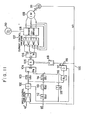
- Fig. 11 shows a basic concept of the slip-frequency type vector controller which comprises of a speed control amplifier 101 to amplify the difference between a command speed ⁇ and excution speeder, a divider 102, a constantsetter 103, a vector analyzer 104 to synthesize a torque current component and exciting current component, a adder 105 to synthesize a vector based on the output of a vector generator which will be described later and the output from the vector analyzer, a converter 106 to convert the adder output into a three-phase current signal, a current control amplifier 107 to amplify the difference between the commanded current value and actual current value, a power for supply to the IM, an induction motor (IM) 109, a three-phase power source 110, a speed detector 111, a differentiator 112, constant setters 113, 114, 115 and 116, a divider 117, an vector generator 118 to determine a speed of rotating field to be given to the IM , and an add
- slip-frequency type vector controller 100 having the basic concept shown in Fig. 11, if it is used as it is as a servo motor, an excessively abrupt acceleration/deceleration occurs so that an overcurrent will flows through the IM. Also even with the primary current through the IM increased, a stalled condition may possible take place in which the torque does not increase.
- the present invention has an object to prevent any shock of the torque caused by an excessively abrupt acceleration/deceleration and also any stalled condition from taking place even when the IM is used as an servo motor, by providing an acceleration/deceleration control apparatus using the slip speed.
- an acceleration/deceleration control apparatus using a slip speed comprising, according to the present invention, a means of detecting an angular frequency or corresponding to an execution speed of the induction motor under the control of the apparatus according to the invnetion, a means of calculating, in response to the torque of the said IM, an angular frequency ⁇ s corresponding to a slip speed derived from vector controller, and a means of comparing an allowable valuers' of the angular frequency ⁇ s with the calculated angular frequency ⁇ s, whereby if the output of the comparing means is the allowable value ⁇ s ⁇ angular frequency ⁇ s, the control having so far been done is continued and if the output is the allowable value ⁇ s' ⁇ angular frequency ⁇ s, the change of commanded position of the induction motor is so inhibited that the angular frequency ⁇ s is less than the allowable value ⁇ s, thus preventing any excessively abrupt acceleration/deceler
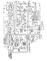
- Fig. 1 shows a circuit diagram showing the first embodiment of the acceleration/deceleration control apparatus using slip speed according to the present invention. It should be noted here that the elements in the basic concept of the conventional slip-frequency type vector controller 100 having been described with reference to Fig. 11 will not be doubly explained here and will be just shown as refereed to with reference numerals.
- the central processing unit (will be referred to as "CPU” hereafter" 1 consisting of a microcomputer, etc. is supplied with a speed command to the IM from an external unit such as the main unit of an NC machine in which the IM is installed which is controlled by the acceleration/deceleration control apparatus according to the present invention.
- the speed command includes a speed of the IM, for example, 1000 rpm.
- the CPU 1 is supplied at the input terminal with, as control signals, with a slow UP/DOWN signal which can designate whether the rotating speed of the IM should be slowly increased/decreased or not, and a signal which can designate whether the IM should be caused to rotate forward or reversely.
- the CPU receives from an A/D converter 31 a "slip speed having been made a parallel signal" D ⁇ s (corresponding to the angular frequency ⁇ r in the claim) calculated from an actual angular frequency (will be referred to as “execution speed” hereafter) ⁇ r obtained from a pulse encoder 111A which detects the output shaft speed of the IM and also from an A/D converter 32 an "execution speed having been made a parallel signal" D ⁇ r (corresponding to the angular frequency ⁇ r in the claim) correspondingly to the abov-mentioned execution speeder.
- the first output port of the CPU is connected to the A input port of a comparator 2 which is provided to detect the acceleration zone or deceleration zone, and the out put is also connected to the first input terminal of an up/down counter 3 which provides an equal-step acceleration.
- the aforementioned up/down counter 3 has the output thereof connected to the B input port of the comparator 2. Further, the output port of the up/down counter 3 is connected to the input terminal of a rate multiplier 4 which can convert a reference frequency from which a reference lock 5 is generated, into a frequency corresponding to a commanded speed to the IM.
- the rate multiplier 4 has connected by means of an AND gate 10 to the other input terminal thereof the output terminal of the reference clock 5 which has a frequency of, for example, 4 MHz.
- the AND gate 10 has connected to the other input terminal thereof the third output terminal of the CPU 1, to provide a signal , as a third means, to designate whether the control having so far been made over the IM is continued or inhibited as will be described later.
- the output terminal of the above-mentioned rate multiplier 4 is connected to the input terminal of a sync circuit 7 which provides a timing for normal operation of a droop counter 15 which will be described later, after the duty ratio is improved by a flip-flop 6 of, for example, D type (will be referred to as "FF" hereafter).
- FF flip-flop 6 of, for example, D type (will be referred to as "FF" hereafter).
- FF flip-flop 6 of, for example, D type (will be referred to as "FF" hereafter).
- To this sync polse generator cercuit 8 provided deparately. Note that these pulse P1 and P2 are sync circuit 7 connected are pulses P1 and P2 from a sync signals used to prevent any "overlapping" with output signal ( ⁇ P ⁇ r) from a sync direction discrmination circuit 33 which will be described later.
- the above-mentioned CPU 1 delivers at the fourth terminal thereof a rotating direction signal which designates the rotating direction of the IM, and this fourth terminal being connected to an inverter 9 and the first input terminal of a first 3-input NAND gate 11.
- the inverter 9 has the output terminal thereof connected to the first input terminal of a second 3-input NAND gate 12 which has the third input terminal of a second 3-input NAND gate 12 which has the third input terminal connected to the third input terminal of the first NAND gate 11 and also to the output terminal of said sync circuit 7.
- a commanded speed ⁇ P ⁇ c serial pulse
- the second input terminal of the 3-input NAND gate 12 is connected to the second input terminal of the 3-input NAND gate 11 and also to the fifth output terminal of the CPU 1 at which a signal is delivered as a second means to designate whether the control having so far been made on the IM is continued or inhibited as will be described later.
- the output terminals of the NAND gates 11 and 12 are connected to the first input terminals, respectively, of OR gates 13 and 14 which are of negative logic.
- this droop counter 15 is composed of an ordinary up/down counter. This droop counter 15 provided to detect a difference between a commanded position and actual position of the rotor of the IM. The difference is a "positional delay" of the rotor which is used as a speed command designating the speed of the induction motor IM.
- the aforementioned droop counter 15 has the output terminal connected to a digital/analogue converter 16 (which will be referred to as "D/A" converter hereafter) which is connected at the output terminal thereof to the input terminal of a speed control amplifier 101 composing the vector controller 100, the speed control amplifier 101 being so arranged as to receive the above-mentioned "positional delay" as an analogu value.
- D/A digital/analogue converter
- the eighth output port of the CPU 1 is connected to one of the terminals of a variable resistor 23 by means of a digital/analogue converter 25 (will be referred to as "D/A converter” hereafter), and the other terminal of the variable resistor 23 is connected the ground.
- the variable terminal of the variable resistor 23 is connected to the input terminal of a voltage'control signal generator 22 which produces a frequency proportional to the input voltage of which the output terminal is connected to the fourth input terminals of the above-mentioned 5-input NAND gates 18 and 19, respectively.
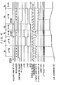
- 2-phase pulse signals (indicated with symbols A and B in the lower portion of Fig. 1) of which the phase is shifted 90 degrees as excution speeder. These 2-phase pulse signals are supplied to the input terminal of a sync direction discrimination circuit 33 where they provide a discrimination of the direction of IM rotation, sent as a serial pulse ⁇ P ⁇ r indicative of the execution speed of IM to a frequency/voltage converter 34 (will be referred to as "F/V converter” hereafter) and also connected to the second input terminals, respectively, of the negative-logic OR gates 13 and 14.
- the above-mentioned +P&)r signal is a signal when the IM rotates forward and the -P ⁇ r signal is a signal when the IM rotates reversely.
- the above-mentioned discrimination circuit 33 receives at input terminal thereof pulses P3 and P4 being the output signals from the sync pulse generator circuit 8, by which the "execution speed P ⁇ r having been made serial pulse" will not overlap "commanded speed P ⁇ c having been made serial pulse".
- the output terminal of said F/V converter 34 is connected by means of an absolute value circuit 35 to an A/D converter 32 of which the output terminal is connected to a secondary magnetic flux generator 36 in which data have previously been stored to excite the IM. Also the F/V converter 34 has the output terminal connectd to the second input terminal of the speed control amplifier 101 and also to the adder 119. That is to say, the output from the F/V converter 34 and the output ( ⁇ s) from the divider 117 are added together in the adder 119 to determine the speed ⁇ of secondary magnetic flux, which is applied to the vector generator 118.
- the signals to designate whether the control having so far been made on the IM is continued or inhibited include the first to third means as having been described in the foregoing but these means may not be used at a same time.
- the first means it is not necessary to deliver the control signal at the third and fifth output terminals of the CPU 1.
- the signal at the seventh output terminal of the CPU 1 may be used to control the outputs of the 5-input NAND gates 18 and 19.
- the signal at the fifth output terminal of the CPU 1 may be used to control the outputs of the 3-input NAND gates 11 and 12.
- the signal at the third output terminal of the CPU 1 may be used to control the output of the 2-input NAND gate 10.
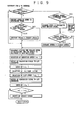
- the flow chart shown in Fig. 2 is the main flow chart in which the whole operation of the acceleration/deceleration control apparatus is shown. Namely, the rotation of the IM is controlled by preventing any excessively abrupt acceleration/deceleration based on the speed command, designations such as rotating direction, slow UP/DOWN, etc. from the external unit.
- the flow chart shown in Fig. 3 is a flow chart of "interval timer interrupt" derived from the main flow chart of Fig. 2, in which an interrupt is applied at every predetermined intervals to check the IM for preventing it from being stalled.
- the IM speed can be controlled in a range from the point of the slip being zero up to a point of the slip reaching the maximum value Sm. Namely, the actual controllable range is limited to a narrow one from the slip being zero. When the slip exceeds the maximum value Sm, the IM speed cannot be controlled. The operation to keep the IM from such speed-uncontrollable condition is called "prevention of IM from being stalled".
- a signal corresponding to the target speed of 1000 rpm is sent from the CPU 1 to the comparator 2, and at the same time, an operation start command signal is sent from the second output terminal of the CPU 1 to the up/down counter 3. Further, a foward rotaiton signal at H level is applied from the fourth output terminal of the CPU 1 to the first input terminal of the 3-input NAND gate 11, while an H-level signal is applied from the sixth output terminal of the CPU 1 to the first input terminal of the 5-input NAND gate 18.
- an H-level signal as "continue” signal is applied from the seventh output terminal of the CPU 1 to the fifth input terminal of the 5-input NAND gate 18, while a D/A data is applied as a signal determining a gradient of slow UP/DOWN from the eighth terminal of the CPU 1 to the D/A converter 25.
- a target speed (1000 rpm in this case) is supplied directly to the up/down counter 3.
- the gate is opened so that the pulse from the voltage control amplifier 22 is suppled as the output signal from the 5-input NAND gate 18 as it is to the UP terminal of the up/down counter 3.
- the equal-step acceleration is done so that the slow UP/DOWN speed is stepwisely increased in the up/down counter 3 (see Fig. 5).
- a stepwise speed increase signal is delivered from the output B port of the up/down counter 3 to the rate multiplier 4. It is converted in this rate multiplier 4 into a signal of double frequency P ⁇ c (slow UP/DOWN commanded speed having been made serial signal) which is applied to the D-FF 6 which provides a signal of frequency P ⁇ c to the sync circuit 7 where it will be synchronied by the external frequencies P1 and P2 to provide a signal of frequency P ⁇ c which is applied to the third terminals, respectively, of the 3-input NAND gates 11 and 12.
- the 3-input NAND gates 11 and 12 have been supplied at the second input terminals thereof with H-level signal from CPU 1 beforehand, so that only the NAND gate 11 has been opened.
- the signal of the above-mentioned frequency Pwc is delivered from only the 3-input NAND gate 11 to the OR gate 13.
- the P ⁇ c i.s sent from the OR gate 13 to the droop counter 15.
- the P ⁇ r is sent from the OR gate 14 to the droop counter 15.
- the output from this droop counter 15 is sent to the vector controller 100 to provide a vector control.
- the P ⁇ r approximates P ⁇ c. Namely, the excution speed ⁇ r approximates the command speed ⁇ c. Since the command speed ⁇ c increases gradually and approximates the target value, the execution speed Or also increases gradually following the increase of the execution speed and finally reaches the target speed.
- the output from the A/D converter 32 is supplied as input to the aforementioned CPU 1 as "execution speed D ⁇ r having been digitalized".
- F/V converted "execution speed having been made serial signal" P ⁇ r is applied from the secondary magnetic flux generator 36 to the differentiation circuit 112 of vector controller 100 by means of the absolute value circuit 35 and the A/D converter 32.
- a slip speed ⁇ is calculated from the execution speed P9r thus supplied according to the principle of vector control and delivered from the absolute value circuit 37 and A/D converter 31 to the CPU 1, as "slip speed having been digitalized" D ⁇ s.
- the speed of the IM 109 is gradually increased and when the garget value (1000 rpm) is finally equal to the execution speed ⁇ r, the inputs to the A port and B port of the comparator 2 are equal to each other as shown in the R2 zone in Fig. 4
- both the NAND gates 18 and 19 are closed so that the output from the voltage control amplifier 22 will not be applied to the up/down counter 3.
- the command speed output ⁇ c from the up/down counter 3 becomes a predetermined value and also the execution speed ⁇ r becomes a predetermined value.
- a control is made to keep the IM 109 at a predetermined speed.
- an H-level signal is delivered from the A ⁇ B terminal of the comparator 2.
- an L-level signal is supplied from the sixth terminal of the CPU 1 and also an H-level signal is supplied to the first terminal.
- an H-level signal is also supplied from the seventh terminal of the CPU 1 to the fifth terminal of the 5-input NAND gate 19, so that the NAND gate 19 will supply the output pulse from the voltage control signal generator 22 to the DOWN terminal of the up/down counter 3.
- the condition corresponds to the "R5 zone" shown in Fig. 4 where the execution speeder of the IM 109 is lowered.
- the slow downed command speed ⁇ c delivered from the up/down counter 3 is sent as P ⁇ c from the OR gate 13 through the rate multiplier 4 and sync circuit 7 to the droop counter 15.
- P ⁇ c is delivered from the OR gate 14 to the droop counter 15.
- the output from the droop counter 15 is sent to the vector controller 100 to provide a vector control.
- P ⁇ r is reduced and approximates PZc.
- the execution speed ⁇ r is decreased and approximates the slow downed command speed ⁇ c. Since the command speed gradually decreases and approximates the target speed, the execution speed ⁇ r also gradually decreases following the gradual decrease of the command speed ⁇ c and will finally reach the target speed.
- the general increase and decrease of the speed of IM 109 are controlled.
- the "interval timer interrupt" shown in Fig. 3 is effected at predetermined intervals for the above-mentioned prevention of IM from being stalled.
- the CPU 1 there is stored a formula for calculating from the execution speeder an "allowable value ⁇ s' of an angular frequency ⁇ s corresponding to slip speed", and the allowable value ⁇ s' and angular frequency ⁇ s are compared at predetermined intervals.
- the allowable value ⁇ s' is equal to or larger than the angular frequency ⁇ s
- the IM is not likely to be stalled. In this case, the control having so far been made over the IM is continued. If “the allowable value ⁇ s' is smaller than the angular frequency ⁇ s", the IM is controlled for the angular frequency ⁇ s to be smaller than the allowable value ⁇ s'
- the means for this control include the first to third inhibiting means or a means to inibit the D/A data delivered from the eighth terminal of the CPU 1.
- the inhibition of the slip angular frequency ⁇ s to be lower than the allowable valuers' needs only the control of the excecution speeder for low acceleration or deceleration. For this purpose, it is necessary to increase or decrease the of the command speed ⁇ c slowly.
- the above-mentioned first to third inhibiting means and the inhibition of the output of D/A converter 25 are destined for inhibiting the increase or decrease of the command speed ⁇ c. Owing to this inhibition, the increase or decrease of the value of the output P ⁇ c of the OR gate 13 is also small. As the result, the output D from the droop counter 15 is delivered to the vector control circuit to control the IM speed.
- the angular frequency of the rotaring magnetic field of the IM changes slowly so that the IM is accelerated or decelerated slowly. If this acceleration or deceleration of the IM is slow, the slip angular frequency WS becomes low and finally less than the allowable value ⁇ s'. Thus, it will not enter the zone where the IM is stalled.
- is supplied to a switch 53a of a switching circuit 53 consisting of, for example, analogue switches. Also the slip speed
- the above-mentioned switching circuit 53 is supplied with a switch on command signal from a CPU 55 which will be described below. Any one of the swiches 53a, 53b and 53c is selected and turned on according to the switch on command signal.
- the output terminal of the A/D converter 54 is connected to the CPU 55 so that an analogue/digital conversion command is supplied from the CPU 55 to the CONV terminal of the A/D converter 54.
- the CPU 55 is supplied at the second input port thereof with a speed command from an external unit, and at the third input port thereof with a control signal from the external unit.
- the data bus from the output of the CPU 55 is connected to the rate multiplier 4, so that a signal i.e. command speed ⁇ c, processed at the CPU 55 is delivered as a data to the rate multiplier 4. Furthermore, the CPU 55 delivers a rotating direction command which designates the rotating direction of the IM, which command is supplied to the first input terminal of the 3-input NAND gate 11 and the first input terminal of the 3-input NAND gate 12 through the inverter 9.
- the acceleration/deceleration control apparatus using slip speed according to the second embodiment of the present invention is constructed as having been described in the foregoing.
- are sent to the switches 53a and 53b, respectively, of the switching circuit 53, and the output from the switching circuit 53 is subjected to the digital conversion in the A/D converter 54 and supplied to the CPU 55.
- the allowable value ⁇ s' of slip speed ⁇ s corresponding to the execution speeder supplied from the A/D converter 54 is read immediately from the table stored in the CPU 55 and which carries the characteristic of "execution speed ⁇ r" vs. "allowable value ⁇ s"' as shown in Fig. 10.
- calculated according to the vector controller are compared with each other. If the result of the comparison is that the "allowable value ⁇ s' is equal to or larger than the angular frequency ⁇ s of slip speed", the control having so far been made is continued. If the result is that "alloiwable value ⁇ s' is smaller than the angular frquency ⁇ s", the IM is so controlled that the angular frequency s becomes less than the allowable value ⁇ s' .
- control signal is supplied to the 3-input NAND gates 11 and 12 or to the AND gate 10.
Landscapes
- Engineering & Computer Science (AREA)
- Power Engineering (AREA)
- Control Of Ac Motors In General (AREA)
Applications Claiming Priority (2)
| Application Number | Priority Date | Filing Date | Title |
|---|---|---|---|
| JP8384786 | 1986-04-11 | ||
| JP83847/86 | 1986-04-11 |
Publications (2)
| Publication Number | Publication Date |
|---|---|
| EP0241867A1 true EP0241867A1 (de) | 1987-10-21 |
| EP0241867B1 EP0241867B1 (de) | 1992-08-12 |
Family
ID=13814093
Family Applications (1)
| Application Number | Title | Priority Date | Filing Date |
|---|---|---|---|
| EP87105269A Expired - Lifetime EP0241867B1 (de) | 1986-04-11 | 1987-04-09 | Beschleunigungs- und Verzögerungssteuerung unter Berücksichtigung des Schlupfes |
Country Status (4)
| Country | Link |
|---|---|
| US (1) | US4818927A (de) |
| EP (1) | EP0241867B1 (de) |
| JP (1) | JPS6348180A (de) |
| DE (1) | DE3781002T2 (de) |
Cited By (2)
| Publication number | Priority date | Publication date | Assignee | Title |
|---|---|---|---|---|
| GB2238920A (en) * | 1989-11-20 | 1991-06-12 | Abb Stroemberg Drives Oy | A method of preventing the stalling of an asynchronous machine |
| GB2244875A (en) * | 1990-05-30 | 1991-12-11 | Toshiba Kk | Controller for compressor driven by induction motor |
Families Citing this family (10)
| Publication number | Priority date | Publication date | Assignee | Title |
|---|---|---|---|---|
| JPH01308104A (ja) * | 1988-06-06 | 1989-12-12 | Mitsubishi Electric Corp | リニアモータ用電気ブレーキ制御方法 |
| JP2845911B2 (ja) * | 1988-12-24 | 1999-01-13 | ファナック株式会社 | 誘導電動機のすべり周波数制御方法 |
| JPH03169291A (ja) * | 1989-11-25 | 1991-07-22 | Hitachi Ltd | 誘導電動機の制御装置 |
| KR930007600B1 (ko) * | 1990-08-14 | 1993-08-13 | 삼성전자 주식회사 | 전동기의 전류위상 지연보상 방법 |
| DE4312949A1 (de) * | 1993-04-21 | 1994-10-27 | Abb Research Ltd | Verfahren zur Steuerung und Regelung eines elektrischen Antriebes eines Fahrzeuges |
| FR2754055B1 (fr) * | 1996-09-27 | 1998-12-18 | Jouan | Dispositif de determination du couple resistant d'un equipement en rotation, systeme de surveillance d'un moteur electrique et systeme de regulation de parametres d'un centrifugeur associe |
| CN1473391B (zh) * | 2001-09-29 | 2012-09-26 | 大金工业株式会社 | 相电流检测方法及相电流检测装置 |
| JP5547866B2 (ja) * | 2007-06-19 | 2014-07-16 | 株式会社日立産機システム | 誘導電動機駆動装置、電動機駆動システム、及び昇降システム |
| US10008854B2 (en) | 2015-02-19 | 2018-06-26 | Enphase Energy, Inc. | Method and apparatus for time-domain droop control with integrated phasor current control |
| KR101855764B1 (ko) * | 2016-04-08 | 2018-05-09 | 현대자동차 주식회사 | 차량용 모터 제어 장치 및 방법 |
Citations (3)
| Publication number | Priority date | Publication date | Assignee | Title |
|---|---|---|---|---|
| FR2218692A1 (de) * | 1973-02-20 | 1974-09-13 | Gen Electric | |
| GB2143688A (en) * | 1983-07-06 | 1985-02-13 | Mitsubishi Electric Corp | Control apparatus for elevator |
| US4559485A (en) * | 1981-08-31 | 1985-12-17 | Kollmorgen Technologies Corporation | Control systems for AC induction motors |
Family Cites Families (1)
| Publication number | Priority date | Publication date | Assignee | Title |
|---|---|---|---|---|
| US4483419A (en) * | 1982-10-12 | 1984-11-20 | Otis Elevator Company | Elevator motoring and regenerating dynamic gain compensation |
-
1986
- 1986-07-03 JP JP61156657A patent/JPS6348180A/ja active Pending
-
1987
- 1987-04-09 EP EP87105269A patent/EP0241867B1/de not_active Expired - Lifetime
- 1987-04-09 US US07/036,056 patent/US4818927A/en not_active Expired - Fee Related
- 1987-04-09 DE DE8787105269T patent/DE3781002T2/de not_active Expired - Fee Related
Patent Citations (3)
| Publication number | Priority date | Publication date | Assignee | Title |
|---|---|---|---|---|
| FR2218692A1 (de) * | 1973-02-20 | 1974-09-13 | Gen Electric | |
| US4559485A (en) * | 1981-08-31 | 1985-12-17 | Kollmorgen Technologies Corporation | Control systems for AC induction motors |
| GB2143688A (en) * | 1983-07-06 | 1985-02-13 | Mitsubishi Electric Corp | Control apparatus for elevator |
Cited By (4)
| Publication number | Priority date | Publication date | Assignee | Title |
|---|---|---|---|---|
| GB2238920A (en) * | 1989-11-20 | 1991-06-12 | Abb Stroemberg Drives Oy | A method of preventing the stalling of an asynchronous machine |
| GB2238920B (en) * | 1989-11-20 | 1993-12-15 | Abb Stroemberg Drives Oy | A method of preventing the stalling of an asynchronous machine |
| GB2244875A (en) * | 1990-05-30 | 1991-12-11 | Toshiba Kk | Controller for compressor driven by induction motor |
| GB2244875B (en) * | 1990-05-30 | 1994-06-01 | Toshiba Kk | Controller for compressor driven by an induction motor and slip detecting apparatus for detecting the slip of an induction motor |
Also Published As
| Publication number | Publication date |
|---|---|
| JPS6348180A (ja) | 1988-02-29 |
| DE3781002D1 (de) | 1992-09-17 |
| DE3781002T2 (de) | 1993-04-01 |
| US4818927A (en) | 1989-04-04 |
| EP0241867B1 (de) | 1992-08-12 |
Similar Documents
| Publication | Publication Date | Title |
|---|---|---|
| EP0589630B1 (de) | Automatische Einstellung der Kommutierungsverzögerung für einen bürstenlosen Gleichstrommotor | |
| EP0214781B1 (de) | Generatorspannungsregelkreis | |
| EP0241867A1 (de) | Beschleunigungs- und Verzögerungssteuerung unter Berücksichtigung des Schlupfes | |
| EP0241920A2 (de) | Regelsystem für einen pulsweiten modulierten Wechselrichter | |
| US4797600A (en) | Magnetic drive control system for a multiple cooling fan installation | |
| US3696278A (en) | Controlling apparatus for a d.c. brushless motor | |
| EP0241045A1 (de) | Bewegungssteuergerät für einen Induktionsmotor | |
| EP0091589A3 (de) | Gerät zum Regeln eines Induktionsmotors | |
| EP0289362B1 (de) | Regulierungssysteme für bürstenlose Motoren | |
| US6356048B1 (en) | Method and device for controlling electric motors of the brushless direct-current type, particularly for moving the weft winding arm in weft feeders for weaving looms | |
| JPS5953795B2 (ja) | サイリスタモ−タの制御装置 | |
| EP0017345B1 (de) | Schlupffrequenzregelung für Induktionsmotoren mit variabler Drehzahl | |
| EP0347465B1 (de) | Verfahren zur steuerung eines servomotors | |
| EP0049241B1 (de) | Verfahren und regelung eines wechselstrominduktionsmotors | |
| EP0144161B1 (de) | Steuer- und Regelsystem für einen Wechselstrom-Motor | |
| US3896349A (en) | Electric drive for motors interconnected to form a ring circuit | |
| EP0456828A1 (de) | Steuerungsverfahren für den antrieb eines motortyps änderlicher reluktanz | |
| JPS5622598A (en) | Starting system for pulse motor | |
| JPS5917632B2 (ja) | ゼロ回転及びゼロ・トルク検出方法および装置 | |
| US6408130B1 (en) | Electric drive system with an electronically commuted DC motor in order to reduce torque irregularities | |
| EP0220814B1 (de) | Einrichtung und Verfahren für Schrittmotorstabilisierung | |
| EP0028139B1 (de) | Nähmaschine | |
| JP3126372B2 (ja) | モータ制御回路 | |
| EP0427571B1 (de) | Wechselstrommotorregelung | |
| EP0178629B1 (de) | Steuereinrichtung mit Indexeinstellung für Wechselrichtergeräte |
Legal Events
| Date | Code | Title | Description |
|---|---|---|---|
| PUAI | Public reference made under article 153(3) epc to a published international application that has entered the european phase |
Free format text: ORIGINAL CODE: 0009012 |
|
| AK | Designated contracting states |
Kind code of ref document: A1 Designated state(s): AT BE CH DE ES FR GB GR IT LI LU NL SE |
|
| RBV | Designated contracting states (corrected) |
Designated state(s): CH DE FR LI |
|
| 17P | Request for examination filed |
Effective date: 19871126 |
|
| 17Q | First examination report despatched |
Effective date: 19900108 |
|
| GRAA | (expected) grant |
Free format text: ORIGINAL CODE: 0009210 |
|
| AK | Designated contracting states |
Kind code of ref document: B1 Designated state(s): CH DE FR LI |
|
| REF | Corresponds to: |
Ref document number: 3781002 Country of ref document: DE Date of ref document: 19920917 |
|
| ET | Fr: translation filed | ||
| PLBE | No opposition filed within time limit |
Free format text: ORIGINAL CODE: 0009261 |
|
| STAA | Information on the status of an ep patent application or granted ep patent |
Free format text: STATUS: NO OPPOSITION FILED WITHIN TIME LIMIT |
|
| 26N | No opposition filed | ||
| PGFP | Annual fee paid to national office [announced via postgrant information from national office to epo] |
Ref country code: FR Payment date: 19950414 Year of fee payment: 9 |
|
| PGFP | Annual fee paid to national office [announced via postgrant information from national office to epo] |
Ref country code: CH Payment date: 19950418 Year of fee payment: 9 |
|
| PGFP | Annual fee paid to national office [announced via postgrant information from national office to epo] |
Ref country code: DE Payment date: 19950627 Year of fee payment: 9 |
|
| PG25 | Lapsed in a contracting state [announced via postgrant information from national office to epo] |
Ref country code: LI Effective date: 19960430 Ref country code: CH Effective date: 19960430 |
|
| REG | Reference to a national code |
Ref country code: CH Ref legal event code: PL |
|
| PG25 | Lapsed in a contracting state [announced via postgrant information from national office to epo] |
Ref country code: FR Effective date: 19961227 |
|
| PG25 | Lapsed in a contracting state [announced via postgrant information from national office to epo] |
Ref country code: DE Effective date: 19970101 |
|
| REG | Reference to a national code |
Ref country code: FR Ref legal event code: ST |