EP0241859B1 - Centre board for a surf board - Google Patents
Centre board for a surf board Download PDFInfo
- Publication number
- EP0241859B1 EP0241859B1 EP87105249A EP87105249A EP0241859B1 EP 0241859 B1 EP0241859 B1 EP 0241859B1 EP 87105249 A EP87105249 A EP 87105249A EP 87105249 A EP87105249 A EP 87105249A EP 0241859 B1 EP0241859 B1 EP 0241859B1
- Authority
- EP
- European Patent Office
- Prior art keywords
- centreboard
- slide
- axis
- pivot axis
- locking
- Prior art date
- Legal status (The legal status is an assumption and is not a legal conclusion. Google has not performed a legal analysis and makes no representation as to the accuracy of the status listed.)
- Expired - Lifetime
Links
Images


Classifications
-
- B—PERFORMING OPERATIONS; TRANSPORTING
- B63—SHIPS OR OTHER WATERBORNE VESSELS; RELATED EQUIPMENT
- B63B—SHIPS OR OTHER WATERBORNE VESSELS; EQUIPMENT FOR SHIPPING
- B63B32/00—Water sports boards; Accessories therefor
- B63B32/60—Board appendages, e.g. fins, hydrofoils or centre boards
- B63B32/64—Adjustable, e.g. by adding sections, by removing sections or by changing orientation or profile
-
- B—PERFORMING OPERATIONS; TRANSPORTING
- B63—SHIPS OR OTHER WATERBORNE VESSELS; RELATED EQUIPMENT
- B63B—SHIPS OR OTHER WATERBORNE VESSELS; EQUIPMENT FOR SHIPPING
- B63B35/00—Vessels or similar floating structures specially adapted for specific purposes and not otherwise provided for
- B63B2035/009—Wind propelled vessels comprising arrangements, installations or devices specially adapted therefor, other than wind propulsion arrangements, installations, or devices, such as sails, running rigging, or the like, and other than sailboards or the like or related equipment
Definitions
- the invention relates to a sword for a sail board, which is pivotally mounted in a sword box about an axis between a substantially vertical position and a folded-in position in the sword box and is adjustable from the top by means of a foot actuation device, which consists of a slide which is in rails guided, displaceable parallel to the longitudinal central axis of the sail board and connected to the sword via a push lever, one end of which is attached to the slide about a first pivot axis and the other end of which is attached to the sword about a second pivot axis which is arranged at a distance from the axis of the sword is.
- a foot actuation device which consists of a slide which is in rails guided, displaceable parallel to the longitudinal central axis of the sail board and connected to the sword via a push lever, one end of which is attached to the slide about a first pivot axis and the other end of which is attached to the sword about a second pivot axis which is arranged at a distance from the axi
- DE-A 2 828 859 discloses a device of this type for a sailing board, but not for pivoting the sword but a fin.
- the known device uses a locking device to lock the carriage in desired positions, in particular its foremost position, in which the sword is fully folded.
- the locking device is heavily loaded when the sword is fully folded and exposed to vibrations e.g. during transport but also when the sail board hits a wave. This can lead to undesired release of the locking device.
- the object of the invention is to provide a simple construction of a sword of the type mentioned, which reliably ensures compliance with the set position of the sword including and in particular the fully folded position.
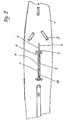
- a sailing board 1 with a sword mechanism 2 has a slide 3 guided in rails 4, 5, which run parallel to the upper edges 6, 7 of a sword box 8. Furthermore, foot straps 9 are uncovered and a foot strap 10 is attached to the slide 3.
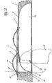
- a sword 11 of the sword mechanism 2 is illustrated in two different positions, the fully collapsed position is shown in solid lines and the substantially vertical position in dashed lines.
- the sword 11 is pivotally mounted about an axis 12 in the front lower region of the sword case 8 and is connected to the carriage 3 via a push lever 13.
- a first end 14 is pivotable about a pivot axis 15 mounted in the slide 3, while the other end 16 of the push lever 13 is pivotally connected to the sword 11 about a second pivot axis 17.
- the second pivot axis 17 is at the greatest possible distance from the axis 12 of the sword 11.
- the pivot axes 15 and 17 are arranged so that in the fully retracted position of the sword 11, which corresponds to the foremost position of the carriage 3 , the dead center of the thrust lever 13 is exceeded.
- the dead center of the thrust lever 13 is illustrated by the dash-dotted line 18, which is crossed by the upper pivot axis 15.
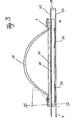
- the rails 4, 5 are designed as U-profile pieces 19, 20, the open sides of which are preferably embedded in the sword case, facing one another.
- the carriage 3 is mounted by means of rollers or sliders 21 tied displaceably within the U-profile pieces 19, 20 (Fig. 3, 4).
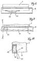
- the carriage 3 is locked in a number of intermediate positions between the two end positions illustrated in FIG. 2 by means of a locking device 22.
- the locking device consists in the upper free leg 23 of the U-profile pieces 19, 20 at intervals provided latching openings 24 into which one or more on the carriage 3 fixed locking pin 25 can engage, which can be moved out of the locking openings 24 by pressing down the carriage 3.
- the slide 3 is provided with four leaf springs 26 which slide on the lower free legs 27 of the U-profile pieces 19, 20 and which in the normal position of the slide 3 against the upper free leg 23 of the U-profile pieces 19, 20 press so that the locking pins 25 are pressed securely into the locking openings 24.
- the springs 26 are dimensioned sufficiently to ensure a secure engagement under all conditions, since the sled 3 can be unlocked by means of the entire body weight of a user with the help of the foot strap 10.
- additional rollers 28 or the like can be provided on the springs 26, which roll instead of the sliding engagement of the springs 26 on the free lower legs 27 of the U-profile pieces 19, 20 hereby improve the smooth running of the carriage 3.
- the sword can thus not be damaged when hitting obstacles, but evades by overrunning the locking device.
- FIGS. 7 and 8 schematically illustrate two exemplary embodiments of the locking pins 25, which allow the locking device 22 to overflow in this way.
- each locking pin 25 has a cam surface 29 which is inclined downwards to the front and which is designed in such a way that the locking pin 25 is pressed downward out of the locking opening 24 against the springs 26 during a violent forward movement of the slide 3.
- the cam surface 29 is provided on the upper side of a spring tongue 30, which in this case forms the locking pin 25.
- the locking device 22 is formed in that the rear edge 31 of the carriage 3 itself forms part of the locking device 22.
- the front end 32 of the carriage 3 is mounted on rollers 33 which run on the lower free leg 28 of the U-profile pieces 19, 20.
- the rear edge 31 forming a locking edge can engage in sawtooth-like raster elevations which act on the lower free legs 27 of the U-profile pieces 19, 20 are formed.
- each U-profile piece 19, 20 is provided on the free edge 35 with an upwardly bent bar 36 which has the raster elevations 34.
- the carriage 3 is simply unlocked by slightly lifting or tipping over the roller 33 via the foot strap 10, so that the rear edge 31 is released from the raster elevations 34.
- a compression spring can also be provided (not shown), which prestresses the rear edge 31 of the carriage 3 downward.
Abstract
Description
Die Erfindung betrifft ein Schwert für ein Segelbrett, welches in einem Schwertkasten um eine Achse zwischen einer im wesentlichen senkrechten und einer im Schwertkasten eingeklappten Stellung schwenkbar gelagert ist und von der Oberseite her mittels einer Fußbetätigungseinrichtung verstellbar ist, die aus einem Schlitten besteht, welcher in Schienen geführt, parallel zur Längsmittelachse des Segelbrettes verschiebbar und mit dem Schwert über einen Schubhebel verbunden ist, dessen eines Ende um eine erste Schwenkachse am Schlitten befestigt ist und dessen anderes Ende um eine zweite Schwenkachse am Schwert befestigt ist, welche im Abstand zur Achse des Schwertes angeordnet ist.The invention relates to a sword for a sail board, which is pivotally mounted in a sword box about an axis between a substantially vertical position and a folded-in position in the sword box and is adjustable from the top by means of a foot actuation device, which consists of a slide which is in rails guided, displaceable parallel to the longitudinal central axis of the sail board and connected to the sword via a push lever, one end of which is attached to the slide about a first pivot axis and the other end of which is attached to the sword about a second pivot axis which is arranged at a distance from the axis of the sword is.
Aus der DE-A 2 828 859 ist eine Einrichtung dieser Art für ein Segelbrett bekannt, allerdings nicht zum Verschwenken des Schwertes sondern einer Finne. Die bekannte Einrichtung verwendet eine Rasteinrichtung, um den Schlitten in gewünschten Positionen, insbesondere seiner vordersten Stellung, in welcher das Schwert vollständig eingeklappt ist, zu arretieren. Die Rasteinrichtung ist bei voll eingeklapptem Schwert hoch belastet und Erschütterungen ausgesetzt z.B. beim Transport aber auch in Fahrt, wenn das Segelbrett auf eine Welle schlägt. Dadurch kann es zur unerwünschten Freigabe der Arretierung kommen.DE-A 2 828 859 discloses a device of this type for a sailing board, but not for pivoting the sword but a fin. The known device uses a locking device to lock the carriage in desired positions, in particular its foremost position, in which the sword is fully folded. The locking device is heavily loaded when the sword is fully folded and exposed to vibrations e.g. during transport but also when the sail board hits a wave. This can lead to undesired release of the locking device.
Aufgabe der Erfindung ist es, eine einfache Konstruktion eines Schwertes der eingangs genannten Art zu schaffen, welche die Einhaltung der eingestellten Lage des Schwertes einschließlich und insbesondere der voll eingeklappten Lage zuverlässig sicherstellt.The object of the invention is to provide a simple construction of a sword of the type mentioned, which reliably ensures compliance with the set position of the sword including and in particular the fully folded position.
Diese Aufgabe wird erfindungsgemäß durch die Merkmale des kennzeichnenden Teils des Anspruchs 1 gelöst.This object is achieved by the features of the characterizing part of
Dank der Erfindung wird eine sichere Verriegelung des eingeklappten Schwertes ohne zusätzlichen Aufwand erreicht.Thanks to the invention, a secure locking of the folded sword is achieved without additional effort.
Obwohl es im Rahmen der Erfindung liegt, das Schwert auch in verschiedenen Zwischenstellungen zu arretieren, so ist eine zusätzliche Verriegelung nur in der voll ausgefahrenen Stellung ausreichend und vereinfacht die Verriegelungseinrichtung und deren Handhabung, insbesondere, wenn der Schlitten eine Fußschlaufe zur Fußbetätigung aufweist. Vorteilhafte Ausgestaltungen der Verriegelungseinrichtung bilden die Gegenstände der Ansprüche 4 bis 8.Although it is within the scope of the invention to lock the sword in various intermediate positions, an additional locking is only sufficient in the fully extended position and simplifies the locking device and its handling, in particular if the slide has a foot strap for foot actuation. Advantageous refinements of the locking device form the subjects of
Dank der Ausgestaltung gemäß Anspruch 9 wird erreicht, daß trotz sicherer Verriegelung des Schwertes beim Auflaufen auf ein Hindernis eine Beschädigung des Schwertes selbst ausgeschlossen ist, indem dieses unter Verschiebung des Schlittens nach vorne nach hinten hochklappen kann.Thanks to the design according to
Anhand der Zeichnung wird die Erfindung beispielsweise näher erläutert.The invention is explained in more detail, for example, with reference to the drawing.
Es zeigen
- Fig. 1 eine Draufsicht auf ein Segelbrett;
- Fig. 2 eine Längsschnittansicht der Schwertlagerung in zwei verschiedenen Stellungen;
- Fig. 3 eine Seitenansicht einer Ausführungsform eines Schlittens in vergrößerter Darstellung;
- Fig. 4 eine Schnittansicht längs der Linie IV-IV von Fig. 3;
- Fig. 5 eine teilweise aufgebrochene Draufsicht des Schlittens gemäß Fig. 4 ohne Fußschlaufe;
- Fig. 6 eine Detailansicht einer abgewandelten Einzelheit des Schlittens gemäß Fig. 3;
- Fig. 7 eine schematische Schnittansicht einer Ausführungsform der Verriegelungseinrichtung;
- Fig. 8 eine Fig. 7 entsprechende Ansicht einer abgewandelten Ausführungsform;
- Fig. 9 eine schematische Schnittansicht einer weiteren Abwandlung der Verriegelungseinrichtung und
- Fig. 10 eine Schnittansicht längs der Linie X-X von Fig. 9.
- Figure 1 is a plan view of a sailing board.
- Figure 2 is a longitudinal sectional view of the sword bearing in two different positions.
- 3 shows a side view of an embodiment of a carriage in an enlarged illustration;
- Fig. 4 is a sectional view taken along the line IV-IV of Fig. 3;
- FIG. 5 shows a partially broken top view of the carriage according to FIG. 4 without a foot strap;
- FIG. 6 shows a detailed view of a modified detail of the carriage according to FIG. 3;
- 7 shows a schematic sectional view of an embodiment of the locking device;
- FIG. 8 shows a view corresponding to FIG. 7 of a modified embodiment;
- Fig. 9 is a schematic sectional view of a further modification of the locking device and
- 10 is a sectional view taken along line XX of FIG .. 9
Ein Segelbrett 1 mit Schwertmechanismus 2 weist einen in Schienen 4, 5 geführten Schlitten 3 auf, die parallel zu den Oberkanten 6, 7 eines Schwertkastens 8 verlaufen. Weiterhin sind Fußschlaufen 9 aufdeckt und eine Fußschlaufe 10 auf dem Schlitten 3 befestigt.A
In Fig. 2 ist ein Schwert 11 des Schwertmechanismus 2 in zwei verschiedenen Stellungen veranschaulicht, wobei die vollständig eingeklappte Stellung in durchgezogenen Linien und die im wesentlichen senkrechte Stellung in gestrichelten Linien gezeigt ist.In Fig. 2, a
Das Schwert 11 ist um eine Achse 12 im vorderen unteren Bereich des Schwertkastens 8 schwenkbar gelagert und mit dem Schlitten 3 über einen Schubhebel 13 verbunden. Ein erstes Ende 14 ist um eine im Schlitten 3 gelagerte Schwenkachse 15 verschwenkbar, während aus andere Ende 16 des Schubhebels 13 um eine zweite Schwenkachse 17 verschwenkbar mit dem Schwert 11 verbunden ist. Um eine günstige Kraftübertragung zu erreichen, liegt die zweite Schwenkachse 17 im größtmöglichen Abstand von der Achse 12 des Schwertes 11. Die Schwenkachsen 15 und 17 sind so angeordnet, daß in der vollständig eingeklappten Lage des Schwertes 11, welche der vordersten Stellung des Schlittens 3 entspricht, der Totpunkt des Schubhebels 13 überschritten ist. Der Totpunkt des Schubhebels 13 ist durch die strichpunktierte Linie 18 veranschaulicht, welche durch die obere Schwenkachse 15 überfahren wird.The
Die Schienen 4, 5 sind als U-Profilstücke 19, 20 ausgebildet, deren offene Seiten aufeinanderzuweisend bevorzugt in den Schwertkasten eingelassen sind. Der Schlitten 3 ist mittels Rollen oder Gleitstücken 21 innerhalb der U-Profilstücke 19, 20 gefesselt verschiebbar gelagert (Fig. 3, 4). Mittels einer Verriegelungseinrichtung 22 wird der Schlitten 3 in einer Anzahl von Zwischenstellungen zwischen den beiden in Fig. 2 veranschaulichten Endlagen verriegelt.The
Gemäß Fig. 5 besteht die Verriegelungseinrichtung aus im oberen freien Schenkel 23 der U-Profilstücke 19, 20 in Abständen vorgesehenen Rastöffnungen 24, in welche ein oder mehrere am Schlitten 3 befestigte Rastzapfen 25 eingreifen können, die durch Herunterdrücken des Schlittens 3 aus den Rastöffnungen 24 herausbewegt werden können. Zu diesem Zweck ist der Schlitten 3 mit vier Blattfedem 26 versehen, welche auf den unteren freien Schenkeln 27 der U-Profilstücke 19, 20 gleiten und welche in der Normalstellung des Schlittens 3 diesen gegen den oberen freien Schenkel 23 der U-Profilstücke 19, 20 drücken, so daß die Rastzapfen 25 sicher in die Rastöffnungen 24 gedrückt werden. Die Federn 26 sind hierbei ausreichend dimensioniert, um ein sicheres Einrasten unter sämtlichen Bedingungen zu gewährleisten, da ja mit Hilfe der Fußschlaufe 10 der Schlitten 3 mittels des gesamten Körpergewichts eines Benutzers entriegelt werden kann.5, the locking device consists in the upper
Wie in Fig. 6 schematisch angedeutet, können bei einer abgewandelten Ausführungsform an den Federn 26 zusätzliche Rollen 28 oder dergl. vorgesehen sein, welche anstelle des gleitenden Eingriffs der Federn 26 auf den freien unteren Schenkeln 27 der U-Profilstücke 19, 20 abrollen, um hierdurch die Leichtgängigkeit des Schlittens 3 zu verbessern.As indicated schematically in FIG. 6, in a modified embodiment,
Sämtliche Ausführungsformen gewährleisten, daß die Verriegelungseinrichtung 22 bei einer Vorwärtsbewegung des Schlittens 3 überlaufen werden kann, da diese Vorwärtsbewegung des Schlittens 3 der Einschwenkbewegung des Schwertes 11 entspricht.All of the embodiments ensure that the
Das Schwert kann somit beim Auflaufen auf Hindernisse nicht beschädigt werden, sondern weicht durch Überlaufen der Verriegelungseinrichtung aus.The sword can thus not be damaged when hitting obstacles, but evades by overrunning the locking device.
In den Figuren 7 und 8 sind schematisch zwei Ausführungsbeispiele der Rastzapfen 25 veranschaulicht, welche ein derartiges Überlaufen der Verriegelungseinrichtung 22 erlauben. Bei der Ausführungsform gemäß Fig. 7 weist jeder Rastzapfen 25 eine nach vorne abwärts geneigte Nockenfläche 29 auf, welche derart gestaltet ist, daß der Rastzapfen 25 bei einer gewaltsamen Vorwärtsbewegung des Schlittens 3 gegen die Federn 26 nach unten aus der Rastöffnung 24 herausgedrückt wird. Bei der Ausführungsform gemäß Fig. 8 ist die Nockenfläche 29 auf der oberen Seite einer Federzunge 30 vorgesehen, welche in diesem Falle den Rastzapfen 25 bildet.FIGS. 7 and 8 schematically illustrate two exemplary embodiments of the
Bei der Ausführungsform gemäß Figuren 9 und 10 wird die Verriegelungseinrichtung 22 dadurch gebildet, daß die Hinterkante 31 des Schlittens 3 selbst einen Teil der Verriegelungseinrichtung 22 bildet. Zu diesem Zweck ist das Vorderende 32 des Schlittens 3 auf Rollen 33 gelagert, welche auf dem unteren freien Schenkel 28 der U-Profilstücke 19, 20 laufen. In der in Fig. 9 veranschaulichten eingerasteten Stellung des Schlittens 3 nimmt dieser daher eine nach hinten geringfügig geneigte Schräglage ein, so daß die eine Rastkante bildende Hinterkante 31 in sägezahnähnliche Rasterhebungen eingreifen kann, welche an den unteren freien Schenkeln 27 der U-Profilstücke 19, 20 ausgebildet sind.In the embodiment according to FIGS. 9 and 10, the
Gemäß Fig. 10 ist der untere freie Schenkel 27 jedes U-Profilstückes 19, 20 an der freien Kante 35 mit einer nach oben umgebogenen Leiste 36 versehen, welche die Rasterhebungen 34 aufweist. Hierdurch wird erreicht, daß die Rasterhebungen 34 den freien Lauf der Rollen 33 nicht behindern. Der Schlitten 3 wird einfach dadurch entriegelt, daß Ober die Fußschlaufe 10 ein geringfügiges Anheben oder Kippen um die Rolle 33 erfolgt, so daß die Hinterkante 31 aus den Rasterhebungen 34 freikommt. Um zu verhindern, daß diese Bewegung selbsttätig während des Betriebs erfolgt, kann noch zusätzlich eine Druckfeder vorgesehen sein (nicht dargestellt), welche die Hinterkante 31 des Schlittens 3 nach unten vorspannt.10, the lower
Claims (9)
Priority Applications (1)
| Application Number | Priority Date | Filing Date | Title |
|---|---|---|---|
| AT87105249T ATE51828T1 (en) | 1986-04-16 | 1987-04-09 | SWORD FOR A SAILBOARD. |
Applications Claiming Priority (2)
| Application Number | Priority Date | Filing Date | Title |
|---|---|---|---|
| DE8610401U | 1986-04-16 | ||
| DE8610401U DE8610401U1 (en) | 1986-04-16 | 1986-04-16 | Sword for a sailing board |
Publications (2)
| Publication Number | Publication Date |
|---|---|
| EP0241859A1 EP0241859A1 (en) | 1987-10-21 |
| EP0241859B1 true EP0241859B1 (en) | 1990-04-11 |
Family
ID=6793728
Family Applications (1)
| Application Number | Title | Priority Date | Filing Date |
|---|---|---|---|
| EP87105249A Expired - Lifetime EP0241859B1 (en) | 1986-04-16 | 1987-04-09 | Centre board for a surf board |
Country Status (3)
| Country | Link |
|---|---|
| EP (1) | EP0241859B1 (en) |
| AT (1) | ATE51828T1 (en) |
| DE (2) | DE8610401U1 (en) |
Families Citing this family (3)
| Publication number | Priority date | Publication date | Assignee | Title |
|---|---|---|---|---|
| DE3716423A1 (en) * | 1987-05-15 | 1988-11-24 | Klepper Beteiligungs Gmbh & Co | Centreboard for a sailing craft, in particular a sailboard |
| GB2227461A (en) * | 1989-01-31 | 1990-08-01 | Robert J C Brookes | Emergency folding fin |
| AU2013204785C1 (en) | 2012-07-09 | 2019-09-05 | Fin Control Systems Pty. Limited | Fin Plug for Water Craft |
Family Cites Families (5)
| Publication number | Priority date | Publication date | Assignee | Title |
|---|---|---|---|---|
| DE2722547A1 (en) * | 1977-05-18 | 1978-11-23 | Hans Joachim Prof Dr Petzold | Tilt adjustment for sailing boat centre-board - uses endless belt drive linked to board and has slider control with retaining ratchet |
| DE2828859A1 (en) * | 1978-06-30 | 1980-01-10 | Hannes Marker | Steering and control fin for surfboard underside - has sector shape pivoted by lever and holding ratchet mechanism which can be built within board |
| DE3038938A1 (en) * | 1980-09-02 | 1982-05-27 | Marker, Hannes, 8100 Garmisch-Partenkirchen | Sail-board with retractable lengthwise sliding dagger board - has additional lower pins in guideways shaped for sliding and swivelling |
| DE3033022A1 (en) * | 1980-09-02 | 1982-04-08 | Hannes 8100 Garmisch-Partenkirchen Marker | Adjustable centre-board for sail-board - has foot-operated slider and includes side guide slots |
| CH656360A5 (en) * | 1983-10-28 | 1986-06-30 | Werner Schaub | Device with a pivoting centreboard for sailboards |
-
1986
- 1986-04-16 DE DE8610401U patent/DE8610401U1/en not_active Expired
-
1987
- 1987-04-09 DE DE8787105249T patent/DE3762218D1/en not_active Expired - Fee Related
- 1987-04-09 EP EP87105249A patent/EP0241859B1/en not_active Expired - Lifetime
- 1987-04-09 AT AT87105249T patent/ATE51828T1/en not_active IP Right Cessation
Also Published As
| Publication number | Publication date |
|---|---|
| EP0241859A1 (en) | 1987-10-21 |
| ATE51828T1 (en) | 1990-04-15 |
| DE3762218D1 (en) | 1990-05-17 |
| DE8610401U1 (en) | 1986-06-12 |
Similar Documents
| Publication | Publication Date | Title |
|---|---|---|
| DE4012295C2 (en) | Seat slider | |
| DE4306312C2 (en) | paper cutter | |
| EP0694440A1 (en) | Roof rack | |
| DE3419289A1 (en) | DEVICE FOR CONTINUOUSLY ADJUSTING THE REAL POSITION OF TWO PARTS TO EACH OTHER | |
| DE3201319A1 (en) | SKI BINDING JAWS | |
| DE2537892A1 (en) | Mobile seat for childrens vehicle - is height adjustable by ratchet arm bearing on underside of table | |
| DE3705330A1 (en) | TABLE | |
| DE2716327A1 (en) | TRANSPORT DEVICE | |
| DE3149230C2 (en) | Foldable crank for a fishing line reel | |
| DE3128169C2 (en) | Removable handle | |
| DE3911165A1 (en) | SEAT SLIDING DEVICE | |
| DE3416485C2 (en) | Pop-out roof for a vehicle | |
| DE3636979C2 (en) | ||
| DE3436358A1 (en) | FOLDING FITTING | |
| EP0241859B1 (en) | Centre board for a surf board | |
| DE2661092C2 (en) | ||
| DE3115837C2 (en) | Storage for the mast base of a sail surfer | |
| DE60100316T2 (en) | SUPPORT ARRANGEMENT ON A VEHICLE DECK | |
| DE19644010B4 (en) | conveyor | |
| DE3038266A1 (en) | TOY VEHICLE | |
| DE2459902A1 (en) | SLIDER BRACKET FOR ASSEMBLING ZIPPERS | |
| DE3230795A1 (en) | Sail surfboard | |
| WO1985004143A1 (en) | Sail-board | |
| EP0346509A1 (en) | Surf board | |
| EP0358862B1 (en) | Mast sleeve for the attachment of a boom to the mast of a sail board |
Legal Events
| Date | Code | Title | Description |
|---|---|---|---|
| PUAI | Public reference made under article 153(3) epc to a published international application that has entered the european phase |
Free format text: ORIGINAL CODE: 0009012 |
|
| AK | Designated contracting states |
Kind code of ref document: A1 Designated state(s): AT CH DE ES FR GB IT LI NL |
|
| 17P | Request for examination filed |
Effective date: 19871208 |
|
| 17Q | First examination report despatched |
Effective date: 19881229 |
|
| GRAA | (expected) grant |
Free format text: ORIGINAL CODE: 0009210 |
|
| AK | Designated contracting states |
Kind code of ref document: B1 Designated state(s): AT CH DE ES FR GB IT LI NL |
|
| PG25 | Lapsed in a contracting state [announced via postgrant information from national office to epo] |
Ref country code: NL Effective date: 19900411 Ref country code: GB Effective date: 19900411 |
|
| REF | Corresponds to: |
Ref document number: 51828 Country of ref document: AT Date of ref document: 19900415 Kind code of ref document: T |
|
| REF | Corresponds to: |
Ref document number: 3762218 Country of ref document: DE Date of ref document: 19900517 |
|
| ET | Fr: translation filed | ||
| ITF | It: translation for a ep patent filed |
Owner name: ORGANIZZAZIONE D'AGOSTINI |
|
| PG25 | Lapsed in a contracting state [announced via postgrant information from national office to epo] |
Ref country code: ES Free format text: LAPSE BECAUSE OF FAILURE TO SUBMIT A TRANSLATION OF THE DESCRIPTION OR TO PAY THE FEE WITHIN THE PRESCRIBED TIME-LIMIT Effective date: 19900722 |
|
| NLV1 | Nl: lapsed or annulled due to failure to fulfill the requirements of art. 29p and 29m of the patents act | ||
| GBV | Gb: ep patent (uk) treated as always having been void in accordance with gb section 77(7)/1977 [no translation filed] | ||
| PLBE | No opposition filed within time limit |
Free format text: ORIGINAL CODE: 0009261 |
|
| STAA | Information on the status of an ep patent application or granted ep patent |
Free format text: STATUS: NO OPPOSITION FILED WITHIN TIME LIMIT |
|
| PGFP | Annual fee paid to national office [announced via postgrant information from national office to epo] |
Ref country code: FR Payment date: 19910321 Year of fee payment: 5 |
|
| 26N | No opposition filed | ||
| PGFP | Annual fee paid to national office [announced via postgrant information from national office to epo] |
Ref country code: AT Payment date: 19910405 Year of fee payment: 5 |
|
| ITTA | It: last paid annual fee | ||
| PG25 | Lapsed in a contracting state [announced via postgrant information from national office to epo] |
Ref country code: LI Effective date: 19910430 Ref country code: CH Effective date: 19910430 |
|
| REG | Reference to a national code |
Ref country code: CH Ref legal event code: PL |
|
| PG25 | Lapsed in a contracting state [announced via postgrant information from national office to epo] |
Ref country code: AT Effective date: 19920409 |
|
| PG25 | Lapsed in a contracting state [announced via postgrant information from national office to epo] |
Ref country code: FR Effective date: 19921230 |
|
| REG | Reference to a national code |
Ref country code: FR Ref legal event code: ST |
|
| PGFP | Annual fee paid to national office [announced via postgrant information from national office to epo] |
Ref country code: DE Payment date: 19930617 Year of fee payment: 7 |
|
| PG25 | Lapsed in a contracting state [announced via postgrant information from national office to epo] |
Ref country code: DE Effective date: 19950103 |
|
| PG25 | Lapsed in a contracting state [announced via postgrant information from national office to epo] |
Ref country code: IT Free format text: LAPSE BECAUSE OF NON-PAYMENT OF DUE FEES;WARNING: LAPSES OF ITALIAN PATENTS WITH EFFECTIVE DATE BEFORE 2007 MAY HAVE OCCURRED AT ANY TIME BEFORE 2007. THE CORRECT EFFECTIVE DATE MAY BE DIFFERENT FROM THE ONE RECORDED. Effective date: 20050409 |