EP0241771A2 - Method for electronic detection of a binding reaction - Google Patents
Method for electronic detection of a binding reaction Download PDFInfo
- Publication number
- EP0241771A2 EP0241771A2 EP87104369A EP87104369A EP0241771A2 EP 0241771 A2 EP0241771 A2 EP 0241771A2 EP 87104369 A EP87104369 A EP 87104369A EP 87104369 A EP87104369 A EP 87104369A EP 0241771 A2 EP0241771 A2 EP 0241771A2
- Authority
- EP
- European Patent Office
- Prior art keywords
- substances
- pair
- base
- antigen
- electrically conductive
- Prior art date
- Legal status (The legal status is an assumption and is not a legal conclusion. Google has not performed a legal analysis and makes no representation as to the accuracy of the status listed.)
- Withdrawn
Links
Images



Classifications
-
- G—PHYSICS
- G01—MEASURING; TESTING
- G01N—INVESTIGATING OR ANALYSING MATERIALS BY DETERMINING THEIR CHEMICAL OR PHYSICAL PROPERTIES
- G01N33/00—Investigating or analysing materials by specific methods not covered by groups G01N1/00 - G01N31/00
- G01N33/48—Biological material, e.g. blood, urine; Haemocytometers
- G01N33/50—Chemical analysis of biological material, e.g. blood, urine; Testing involving biospecific ligand binding methods; Immunological testing
- G01N33/53—Immunoassay; Biospecific binding assay; Materials therefor
- G01N33/543—Immunoassay; Biospecific binding assay; Materials therefor with an insoluble carrier for immobilising immunochemicals
- G01N33/54366—Apparatus specially adapted for solid-phase testing
- G01N33/54373—Apparatus specially adapted for solid-phase testing involving physiochemical end-point determination, e.g. wave-guides, FETS, gratings
- G01N33/5438—Electrodes
-
- Y—GENERAL TAGGING OF NEW TECHNOLOGICAL DEVELOPMENTS; GENERAL TAGGING OF CROSS-SECTIONAL TECHNOLOGIES SPANNING OVER SEVERAL SECTIONS OF THE IPC; TECHNICAL SUBJECTS COVERED BY FORMER USPC CROSS-REFERENCE ART COLLECTIONS [XRACs] AND DIGESTS
- Y10—TECHNICAL SUBJECTS COVERED BY FORMER USPC
- Y10S—TECHNICAL SUBJECTS COVERED BY FORMER USPC CROSS-REFERENCE ART COLLECTIONS [XRACs] AND DIGESTS
- Y10S436/00—Chemistry: analytical and immunological testing
- Y10S436/806—Electrical property or magnetic property
-
- Y—GENERAL TAGGING OF NEW TECHNOLOGICAL DEVELOPMENTS; GENERAL TAGGING OF CROSS-SECTIONAL TECHNOLOGIES SPANNING OVER SEVERAL SECTIONS OF THE IPC; TECHNICAL SUBJECTS COVERED BY FORMER USPC CROSS-REFERENCE ART COLLECTIONS [XRACs] AND DIGESTS
- Y10—TECHNICAL SUBJECTS COVERED BY FORMER USPC
- Y10S—TECHNICAL SUBJECTS COVERED BY FORMER USPC CROSS-REFERENCE ART COLLECTIONS [XRACs] AND DIGESTS
- Y10S436/00—Chemistry: analytical and immunological testing
- Y10S436/807—Apparatus included in process claim, e.g. physical support structures
-
- Y—GENERAL TAGGING OF NEW TECHNOLOGICAL DEVELOPMENTS; GENERAL TAGGING OF CROSS-SECTIONAL TECHNOLOGIES SPANNING OVER SEVERAL SECTIONS OF THE IPC; TECHNICAL SUBJECTS COVERED BY FORMER USPC CROSS-REFERENCE ART COLLECTIONS [XRACs] AND DIGESTS
- Y10—TECHNICAL SUBJECTS COVERED BY FORMER USPC
- Y10S—TECHNICAL SUBJECTS COVERED BY FORMER USPC CROSS-REFERENCE ART COLLECTIONS [XRACs] AND DIGESTS
- Y10S436/00—Chemistry: analytical and immunological testing
- Y10S436/807—Apparatus included in process claim, e.g. physical support structures
- Y10S436/809—Multifield plates or multicontainer arrays
Definitions
- This invention relates to a new method for electronically detecting a binding reaction between a pair of chemical substances, particularly biogenic substances such as antigens and antibodies.
- the present invention further provides a new method for electronic immunoassay.
- Antibodies typically act to neutralize microscopic foreign substances by binding to them and destroying them or rendering them harmless.
- Antibodies are globulin proteins of the blood plasma and are often referred to as gamma globulins.
- Antigens related to invading organisms comprise a foreign substance that comes from the invading organism, such as a piece of bacterium or virus. More generally, an antigen is any substance capable of triggering an immune response. Certain specialized cells of the body contact an antigen and produce antibodies specifically designed for that antigen. When released in the body, such antibodies identify and bind to the antigen, thereby combating the infection. Antibodies are highly specific and will generally bind only to the antigen which stimulated their creation.
- an immunodiagnostic test is performed using a sample of the patient's blood.
- the sample is mixed with a solution known to contain antibody specific to a certain disease or condition. If an antigen-antibody reaction occurs, the test result is positive, and the antigen is detected.
- a solution or reagent known to contain a certain antigen can be used to determine whether or not the corresponding antibody is present in a sample.
- the antigen-antibody reaction occurs on a microscopic level and is not readily observable.
- all known immunodiagnostic tests provide some type of means for indicating that the antigen-antibody reaction has occurred.
- electroactive endpoint means a change in electrical properties which indicates that a binding reaction has occurred, such as a change in current, voltage, or resistance as a result of the antigen-antibody reaction.
- One such technique utilizes field effect transistors coated with a layer of antibody in the gate region. If an antigen-antibody reaction occurs, the charge concentration of the transistor changes. Examples of this type of system are given in Schenck U.S. Patent No. 4,238,757, issued December 9, 1980; Guckel U.S. Patent No. 4,180,771, issued December 25, 1981; and Malmros U.S. Patent No. 4,334,880, issued June 15, 1982.
- a voltammetric immunoassay can be carried by labeling one immunoreactant with an electroactive substance.
- Pace U.S. Patent No. 4,233,144, issued November 11, 1980 is illustrative of one such technique.
- Another method involves sandwiching an antigen-antibody layer between two conductive layers and measuring the electrical capacitance of the resulting laminate.
- Giaever U.S. Patent No. 4,054,646, issued October 18, 1977 describes such a method.
- a further method combines change effect signal detection with an enzyme immunoassay technique. Such a method is disclosed by Gibbons U.S. Patent No. 4,287,300, issued September 1, 1981.
- the foregoing electrical methods have, however, failed to provide medical practioners and laboratories with a simple, fast, sensitive, inexpensive and easy-to-use method of performing an immunodiagnostic test.
- colloidal gold refers to a suspension of fine gold particles in water or aqueous solution, which gold particles have a particular antibody bound to the outer surfaces thereof. Preparation of such particles is disclosed by DeMey, et al. U.S. Patent No. 4,446,238, issued May 1, 1984, and DeMey, et al. U.S. Patent No. 4,420,558, issued December 13, 1983. The entire contents of both such DeMey patents are incorporated herein by reference.
- colloidal gold preparations have been previously used in immunodiagnostic tests wherein the results are determined optically by observing small amounts of light reflected as a result of the antigen-antibody reaction.
- the foregoing patents to DeMey disclose a bright field light method of the foregoing type.
- the present invention advantageously employs colloidal gold in a new immunodiagnostic method utilizing an electronic endpoint.
- the present invention provides an advantageous method for detecting a binding reaction between a pair of first and second substances, particularly biogenic substances, which bind together to form a chemical complex.
- the method of the invention involves bringing the substances together so that the binding reaction between them causes completion (closing) of an open electrical circuit. The resulting change in the electrical state of the circuit indicates the binding reaction.
- a diagnostic element for use in detecting a binding reaction comprises a pair of spaced-apart, electrical conductors, particularly conductive layers, disposed side-by-side on a non-electrically conductive base.
- the space between these conductors can define a narrow channel.
- One of a pair of substances which bind to each other is deposited on and affixed to the surface of the non-conductive base between the conductors, e.g., on the bottom wall of the channel.
- Means forming an electrical circuit can be connected to each of the electrically conductive layers so that the channel constitutes a break in the circuit.
- diagnostic element refers to the base, conductors, and layer of one of the binding substances, without the means defining the electrical circuit.
- diagnostic element and means forming an electrical circuit can readily be used in conjunction with any suitable means for bridging the break in the circuit due to the binding reaction between the pair of substances.
- One such means involves adhering one of the substances to the surfaces of electrically conductive particles, as described in detail below.
- the foregoing method for detecting a reaction between complex-forming substances is specifically applied to detection of an antigen-antibody reaction.
- the degree of aggregate formation, and the resulting electrical change, can be used to determine whether a patient sample contains a given antibody or antigen, as will be described in detail below.
- the method of the present invention is particularly useful for detecting antigens in the body of a living creature.
- antigens include drugs, toxins, hormones, allergens, tumor markers, factors, enzymes, steroids, nucleotides and other substances as listed in Huang U.S. Patent No. 4,327,073, issued April 27, 1982, the entire content of which is incorporated herein by reference. Any of the foregoing listed substances can provoke the production of a reactive substance (antibody) which reacts with and binds to the antigen.
- the method of the present invention is useful for detection of a wide variety of substances which may be present in the living body of a human or lower animal.
- the method of the invention is especially useful in drug overdose treatment, where it is desired to quickly determine which drug a patient has taken.
- the method of the invention is also highly useful for detecting the presence of an antigen in the patient's bloodstream associated with a particular disease or condition.
- FIGs 1A-1E schematically illustrate a procedure for detecting an antigen according to the present invention.
- a patient sample 11A such as whole blood, blood serum or urine, containing a particular antigen 12A is mixed with a colloidal gold preparation 13A, (FIG. 1B) containing a predetermined amount of gold particles 14A having antibodies 15A fixed to the outer surfaces thereof.
- Antibodies 15A specifically bind to antigen 12A (FIG. 1C).
- antigen 12A binds with available antibodies 15A, resulting in free complexes 18A, comprising both antigen 12A and antibody 15A bound to particles 14A. Since there are more antibodies 15A than antigens 12A, some antibodies 15A remain free, i.e., unbound to an antigen 12A.
- the foregoing procedure is also carried out using a control sample 11B (FIG. 2A) lacking the antigen 12A and a second colloidal gold preparation 13B (FIG. 2B) substantially identical in composition to preparation 13A used with patient sample 11A.
- the thus-formed second mixture 16B (FIG. 2C) lacks the complexes 18A shown in Figure 1A, and correspondingly has a greater number of particles 14B having unbound antigen 15B on the surfaces thereof.
- the first mixture 16A, corresponding to the patient sample (FIG. 1C), and the second mixture 16B (FIG. 2C), corresponding to the control, are then ready for use with a reaction detector 20 according to the invention (FIGS. 1D, 2D).
- reaction detector 20 includes a non-electrically conductive base 22, a pair of thin, spaced-apart electrically conductive layers 23, 24 disposed side-by-side on base 22 with a channel 32 formed therebetween, and means defining an electrical circuit, such as an ohmmeter 26 functionally connected to layers 23, 24 as shown by means such as wires 28.
- Base 22 is typically made of a non-conductive material, such as polystyrene, glass or crystaline silicon.
- Layers 23, 24 may be formed of any conductive material, particularly an electrically conductive metal such as, for example, gold, silver, copper, chromium or aluminum.
- first and second reaction detectors 20A (FIG. 1D) and 20B (FIG. 2D) are prepared in advance for use with mixtures 16A, 16B, respectively.
- Samples of antigen in a carrier liquid e.g., water or saline solution
- a carrier liquid e.g., water or saline solution
- antigen layers 30A, 30B are made of the same type of antigen as antigen 12A to be detected.
- first mixture 16A (FIG. 1C), corresponding to patient sample 11A (FIG. 1A), is poured into channel 32A of first detector 20A under conditions effective to cause binding of antigen layer 30A and antibody 15A.
- the foregoing procedure is also carried out using the control mixture 16B (lacking complexes 18A) and second detector 20B (FIG. 2E).
- Conductive particles 14A having free antibodies 15A thereon effectively become bound to bottom wall 33A via antigen layer 30A due to the antigen-antibody binding reaction.
- the reaction conditions employed to incubate the antigen-antibody reaction are well known.
- Complexes 18A containing antigen 12A from sample 11A do not tend to become bound to bottom wall 33A.
- channel 32A may, if desired, be flushed with a suitable liquid, e.g., water or saline solution, to wash away any unbound particles 14A, then dried by any suitable means, such as heating or allowing the reaction detector to stand open to the air.
- Figure 4A corresponds to the same state as Figure 1E
- Figure 4B corresponds to the same state as Figure 2E
- Figures 4A, 4B illustrate the differences in the extent of the binding reaction not apparent in Figures 1E, 2E.
- Ohmmeters 26A and 26B register the resistance across channels 32A and 32B for each of the detectors 20A and 20B.
- For the control (FIG. 4B) all particles 14B having free antibodies 15B deposited thereon are available for binding with antigen layer 30B bound to bottom wall 33B. As a result, complexes 35B are formed at bottom wall 33B and are anchored thereto.
- aggregates 39B effectively provide an electrical connection between layers 23B and 24B, completing an electrical circuit defined by ohmmeter 26B, wires 28B, layers 23B, 24B, and aggregates 39B. This is reflected by the resistance reading given by ohmmeter 26B. A drastic decrease in resistance occurs as a result of bridging of aggregates 39B.
- the reaction for the mixture 16A corresponding to the patient sample proceeds in a similar fashion, except that this mixture 16A already contains complexes 18A formed by reaction of antigen 12A with antibody 15A. Since the antibodies of these complexes 18A are already bound with at least some antigen 12A, these complexes 18A do not tend to bind to the layer of antigen 30A at bottom wall 33A.
- the number of free antibodies 15A deposited on particles 14A is less than in mixture 16B, since some of these antibodies 15A were used to form complexes 18A.
- aggregates 39A form, but there are fewer such aggregates, and correspondingly less bridging of channel 32A.
- the decrease in resistance registered by ohmmeter 26A is less than the decrease in resistance registered by ohmmeter 26B.
- This difference in readings indicates the presence of antigen 12A in the patient sample 11A. If patient sample 11A does not contain any antigen 12A, then the decrease in resistance for reaction detector 20A would be the same as the decrease in resistance for detector 20B.
- Conductive particles 14A,B are larger than antigen 12A and antibodies 15A,B.
- a number of antibodies 15A,B are bound to a single conductive particle 14A or 14B, and similarly a number of antigens 12A can bind with antibodies 15A on the surface of a single particle 14A or 14B.
- Figure 5 schematically illustrates how a conductive particle 14B having antibodies 15B on its surface becomes bound to bottom wall 33B via antigen layer 30B.
- Complexes 18A as referred to above may in fact comprise particles 14A having some free antibodies 15A on the surfaces thereof and some antibodies 15A bound to antigens 12A. In these complexes 18A, however, the proportion of free antibodies (unbound to antigen 12A in mixture 16A) is low enough so that the complex 18A will not subsequently bind to bottom wall 33A of channel 32A.
- the reaction detector 20 used in the foregoing procedure is specifically designed as follows.
- the width of the channel 32 may vary, particularly in relation to the simple numerical average diameter of the conductive particles forming a chain to bridge channel 32.
- the following table states preferred ranges for dimensions according to the present invention:
- a 20:1 ratio of channel width to average particle diameter is typical, e.g., the channel has a width of 10 microns, and the average diameter of the conductive particles is 0.5 microns.
- antigens have an affinity for polystyrene and tend to become bound thereto under certain conditions. Antibodies by contrast readily become bound to the surfaces of fine metal particles, such as gold particles, using the procedure described below.
- fine metal particles such as gold particles.
- Layers 23, 24 may have any desired dimensions which prove functional. These layers 23, 24 are preferably as thin as possible, and preferably have a thickness no greater than about 0.5 microns, particularly a thickness in the range of 0.001-0.005 microns. Conventional sputter deposition can be readily used to form layers 23, 24. Layers 23, 24 may have any desired shape, such as rectangular (per Fig. 2) or semicircular so as to define a circular "dot" on the non-conductive base. Generally, base 22 is made of plastic, preferably methyl cellulose, nylon or polystyrene. Base 22 is most preferably made of polystyrene of the type used to make microscope slides, since the polarity of antigen molecules causes such molecules to bind to the base to form a substantially complete, homogenous coating of antigen.
- Glass by itself is not generally employed as base 22 since antigens have a poor affinity for a glass surface and it has proved difficult to adhere a layer of antigen to a glass slide.
- a glass slide can be surface treated so that antigen affinity for the coating on the glass slide becomes about as great as antigen affinity for a polystyrene slide. This surface treatment comprises coating the glass slide with a thin layer of titanium oxynitride (TiO x N y ). An example of this technique appears below.
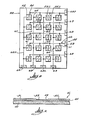
- Figure 8 illustrates a further embodiment of the diagnostic element of the invention wherein a multiplicity of layers 23, 24 are disposed on a single non-conductive base 22.
- Conductive means 28 for this embodiment comprises a series of individual electrical conductors 61 which each connect to a common conductor 62 which in turn connects to a terminal plate 63 mounted on the edge of base 22. Pairs of layers 23, 24 are arrayed in rows and columns on base 22.
- rows of plates 63 are disposed on adjacent sides of rectangular base 22.
- all but one of conductors 62 of second set 67 are located on the reverse side of base 22.
- These conductors 62 are illustrated by broken lines in Figure 8.
- Outer conductor 62A does not cross any conductors 62 of first set 66 and thus does not need to be on the other side of base 22, although it can be so located if desired.
- Individual conductors 61 connected to common conductors 62 of second set 67 on the reverse side of base 22 include portions 69 which extend through the thickness of base 22 and connect with such conductors 62 (shown by broken lines in Fig. 7).
- Ohmmeter 26 can be connected to various combinations of terminal plates 63 to measure resistance for each pair of layers 23, 24. To make such a measurement, ohmmeter 26 is connected to two plates 63 on different edges of base 22. In the embodiment of Fig. 8, connecting an ohmmeter to plates 63C, 63D would test the indicated pair of layers 23C, 24D.
- the foregoing embodiment allows a single diagnostic element according to the invention to test a single patient sample for a number of different substances, such as antigens, since each pair of layers 23, 24 can have a different substance bound therebetween, or have no substance bound therebetween so as to provide a control, as described above.
- the following procedure was used to make a suspension of gold particles labeled with antibodies according to the present invention.
- About 1 ml (milliliter) of a 1% w/v (weight/volume) solution of gold chloride in water were mixed with about 0.1 ml of Kodak D-19 photographic developer (containing a weak acid) to reduce the gold chloride to form gold particles.
- the resulting mixture was washed with distilled water by centrifugation at about 15,000 g to obtain a suspension of pure gold particles in water.
- Goat anti-rabbit IgG antibodies were added to a pH 9.6 carbonate buffer to form an aqueous 1:5,000 (w/v) antibody solution. 1.0 ml of this solution was added to the gold particles, and the resulting mixture was allowed to set overnight at room temperature. The gold particles from this mixture, bound with the goat anti-rabbit IgG, were washed by centrifugation at about 15,000 g with phosphate buffered saline to remove excess antibody.
- Titanium oxynitride (TiO x N y ). Titanium oxynitride flims of varying composition were deposited onto the glass slides by radio-frequency (rf) magnetron sputter deposition.
- the instrument used to deposit the titanium oxynitride coating was a Materials Research Corporation Model 822 Sputtersphere. A titanium target was used as the cathode.
- the system base pressure was 3 x 10 ⁇ 7 Torr.
- the system was backfilled with a mixture of nitrogen and oxygen. Sputtering occurred at a total pressure of 8 x 10 ⁇ 3 Torr.
- the forward power was 1,500W
- the target voltage was 314V
- reflected power was 0 watts
- cathode to anode distance was 21 ⁇ 2 inches and the sputtering time was 30 minutes.
- the oxynitride materials were formed by reactive deposition in an oxygen/nitrogen plasma.
- the ratio of oxygen to nitrogen was varied to change the film composition.
- the composition of the film was then determined with Auger electron spectroscopy.
- a nitrogen to oxygen molar ratio of .30 to .40 yielded a film having superior antigen adherence.
- the amount of antigen adherence on the TiO x N y films was comparable to that on plastic slides and was an order of magnitude larger than antigen adherence to uncoated glass under similar conditions.
- a gold-palladium alloy (60:40) was then evaporated onto the upper surface of each slide 40 to form an evenly distributed gold-palladium layer 41 having a thickness of 1,000 angstroms on each slide 40.
- a scratch (line) 42 was then made in the surface of each gold-palladium layer 41 between points 46, 47 using a sharp needle.
- a blunt instrument was used to rub away layer 41 in areas 48, 49.
- the result left a pair of 1,000 angstrom thick conductive layers 51, 52 separated by non-conductive line 42.
- An ohmmeter reading on areas 51, 52 (across line 42) gave a reading of greater than 2 million ohms.
- aqueous rabbit IGG solution was placed along the entire length of line 42 and incubated for 18 hours (overnight) to form an antigen layer 53
- the IGG solution was then removed and the slides 40 were rinsed with phosphate buffered saline solution.
- the previously prepared colloidal suspension of gold-tagged anti-rabbit-IGG gold particle diameters 0.1-0.5 mm was then applied to line 42.
- Figure 10 illustrates the results for a control slide processed in the same manner as slides 40 except that the control slide was not treated with rabbit IGG solution. As this microphotograph indicates, only a few small aggregates remained on this slide segment after rinsing with phosphate buffered saline solution.
Landscapes
- Health & Medical Sciences (AREA)
- Immunology (AREA)
- Life Sciences & Earth Sciences (AREA)
- Engineering & Computer Science (AREA)
- Molecular Biology (AREA)
- Biomedical Technology (AREA)
- Chemical & Material Sciences (AREA)
- Hematology (AREA)
- Urology & Nephrology (AREA)
- Biotechnology (AREA)
- Biochemistry (AREA)
- Cell Biology (AREA)
- Food Science & Technology (AREA)
- Medicinal Chemistry (AREA)
- Physics & Mathematics (AREA)
- Analytical Chemistry (AREA)
- Microbiology (AREA)
- General Health & Medical Sciences (AREA)
- General Physics & Mathematics (AREA)
- Pathology (AREA)
- Investigating Or Analyzing Materials By The Use Of Electric Means (AREA)
- Measuring Or Testing Involving Enzymes Or Micro-Organisms (AREA)
- Medicines Containing Antibodies Or Antigens For Use As Internal Diagnostic Agents (AREA)
Abstract
A method is disclosed for detecting the occurrence of a binding or complex-forming reaction between specific substances (12, 15) by utilizing the binding reaction to complete an electrical circuit, and then measuring a change in the electrical state of this circuit. In a preferred embodiment, a layer of antigen (12) is coated onto a non-conductive base (22) between a pair of electrically conductive layers (23, 24) superposed on the base (22). Antibodies (15) which react with the foregoing antigen are treated so that they become bound to fine electrically conductive, metallic particles (14). The electrically conductive particles (14) having antibody (15) bound thereto are then added to the antigen layer (12) deposited on the base (22) and allowed to react therewith. Electrically conductive particles (14) are thereby bound to the base (22) due to the binding reaction between the antigen and antibody to thereby form aggregates (39) of electrically conductive particles (14) which bridge the electrically conductive layers (23, 24) and complete the circuit. Such a method is useful for the detection of antigens in the blood serum of a human patient.
Description
- This invention relates to a new method for electronically detecting a binding reaction between a pair of chemical substances, particularly biogenic substances such as antigens and antibodies. The present invention further provides a new method for electronic immunoassay.
- It is a well known principle of immunology that living organisms produce microscopic substances called antibodies to defend the body against invading foreign substances or microorganisms, such as bacteria and viruses. Antibodies typically act to neutralize microscopic foreign substances by binding to them and destroying them or rendering them harmless. Antibodies are globulin proteins of the blood plasma and are often referred to as gamma globulins.
- When a foreign substance such as a bacterium or virus enters a human or animal body, production of antibodies to combat the infection is stimulated by the presence of one or more antigens. Antigens related to invading organisms comprise a foreign substance that comes from the invading organism, such as a piece of bacterium or virus. More generally, an antigen is any substance capable of triggering an immune response. Certain specialized cells of the body contact an antigen and produce antibodies specifically designed for that antigen. When released in the body, such antibodies identify and bind to the antigen, thereby combating the infection. Antibodies are highly specific and will generally bind only to the antigen which stimulated their creation.
- When a person has been infected with certain diseases, that person's blood will often contain measurable levels of antigen specific to that disease. To determine whether such an infection is present, an immunodiagnostic test is performed using a sample of the patient's blood. The sample is mixed with a solution known to contain antibody specific to a certain disease or condition. If an antigen-antibody reaction occurs, the test result is positive, and the antigen is detected. Such a test is typically reversible, i.e., a solution or reagent known to contain a certain antigen can be used to determine whether or not the corresponding antibody is present in a sample. However, the antigen-antibody reaction occurs on a microscopic level and is not readily observable. Thus, all known immunodiagnostic tests provide some type of means for indicating that the antigen-antibody reaction has occurred.
- A variety of techniques have been used to detect antigen-antibody reactions. The principal techniques presently in use are enzyme immunoassay, immunofluorescence, and radioimmunoassay. In typical enzyme immunoassay procedures, the antigen-antibody reaction is detected by the formation, by an enzyme, of a colored product from a colorless substrate. Immunofluorescence techniques indicate that a reaction has occurred by emission of small quantities of light which must generally be observed microscopically. Radioimmunoassay utilizes radioactive labeling substances so that occurrence of the antigen-antibody reaction is measured by the presence or absence of small amounts of radioactivity. These known methods are reliable but are slow and tedious.
- Recently several types of electrical immunoassay techniques have been developed. Such methods utilize an electronic endpoint for measuring immune reactions. As used herein, "electronic endpoint" means a change in electrical properties which indicates that a binding reaction has occurred, such as a change in current, voltage, or resistance as a result of the antigen-antibody reaction.
- One such technique utilizes field effect transistors coated with a layer of antibody in the gate region. If an antigen-antibody reaction occurs, the charge concentration of the transistor changes. Examples of this type of system are given in Schenck U.S. Patent No. 4,238,757, issued December 9, 1980; Guckel U.S. Patent No. 4,180,771, issued December 25, 1981; and Malmros U.S. Patent No. 4,334,880, issued June 15, 1982.
- Several other methods have been proposed for measuring immunologic reactions electrically. A voltammetric immunoassay can be carried by labeling one immunoreactant with an electroactive substance. Pace U.S. Patent No. 4,233,144, issued November 11, 1980, is illustrative of one such technique. Another method involves sandwiching an antigen-antibody layer between two conductive layers and measuring the electrical capacitance of the resulting laminate. Giaever U.S. Patent No. 4,054,646, issued October 18, 1977, describes such a method. A further method combines change effect signal detection with an enzyme immunoassay technique. Such a method is disclosed by Gibbons U.S. Patent No. 4,287,300, issued September 1, 1981. The foregoing electrical methods have, however, failed to provide medical practioners and laboratories with a simple, fast, sensitive, inexpensive and easy-to-use method of performing an immunodiagnostic test.
- One aspect of the present invention involves the use of antigen or antibody-labeled colloidal gold particles. In general, "colloidal gold" refers to a suspension of fine gold particles in water or aqueous solution, which gold particles have a particular antibody bound to the outer surfaces thereof. Preparation of such particles is disclosed by DeMey, et al. U.S. Patent No. 4,446,238, issued May 1, 1984, and DeMey, et al. U.S. Patent No. 4,420,558, issued December 13, 1983. The entire contents of both such DeMey patents are incorporated herein by reference. Such colloidal gold preparations have been previously used in immunodiagnostic tests wherein the results are determined optically by observing small amounts of light reflected as a result of the antigen-antibody reaction. The foregoing patents to DeMey disclose a bright field light method of the foregoing type. The present invention advantageously employs colloidal gold in a new immunodiagnostic method utilizing an electronic endpoint.
- The present invention provides an advantageous method for detecting a binding reaction between a pair of first and second substances, particularly biogenic substances, which bind together to form a chemical complex. The method of the invention involves bringing the substances together so that the binding reaction between them causes completion (closing) of an open electrical circuit. The resulting change in the electrical state of the circuit indicates the binding reaction.
- According to a further aspect of the invention, a diagnostic element for use in detecting a binding reaction comprises a pair of spaced-apart, electrical conductors, particularly conductive layers, disposed side-by-side on a non-electrically conductive base. The space between these conductors can define a narrow channel. One of a pair of substances which bind to each other is deposited on and affixed to the surface of the non-conductive base between the conductors, e.g., on the bottom wall of the channel. Means forming an electrical circuit can be connected to each of the electrically conductive layers so that the channel constitutes a break in the circuit. As used herein, the term "diagnostic element" refers to the base, conductors, and layer of one of the binding substances, without the means defining the electrical circuit. Such a diagnostic element and means forming an electrical circuit can readily be used in conjunction with any suitable means for bridging the break in the circuit due to the binding reaction between the pair of substances. One such means involves adhering one of the substances to the surfaces of electrically conductive particles, as described in detail below.
- According to another aspect of the invention, the foregoing method for detecting a reaction between complex-forming substances is specifically applied to detection of an antigen-antibody reaction. The degree of aggregate formation, and the resulting electrical change, can be used to determine whether a patient sample contains a given antibody or antigen, as will be described in detail below.
- Preferred exemplary embodiments will hereafter be described in conjunction with the appended drawing, wherein like designations denote like elements, and:
- Figures 1A, 1B, 1C, 1D and 1E and Figures 2A, 2B, 2C, 2D and 2E are schematic diagrams illustrating an immunodiagnostic method according to the invention;
- Figure 3 is a schematic diagram illustrating a reaction detector according to one embodiment of the invention;
- Figures 4A and 4B are schematic diagrams showing aggregate formation according to the method of Figures 1A-1E and 2A-2E, respectively;
- Figure 5 is a schematic diagram showing binding of a conductive particle to a non-conductive base according to one embodiment of the invention;
- Figure 6 is a schematic diagram of a diagnostic element according to one embodiment of the invention;
- Figure 7 is a cross-sectional view of the diagnostic element of Figure 6;
- Figure 8 is a schematic diagram of a multiple diagnostic element according to the invention;
- Figure 9 is a microphotograph of a sample slide at a magnification of 5,000 showing formation of aggregates according to one example of the present invention; and
- Figure 10 is a microphotograph of a control slide lacking aggregates at a magnification of 800.
- Figures 1 through 8 are not to scale. Figures 9 and 10 are to scale.
- The method of the present invention is particularly useful for detecting antigens in the body of a living creature. Such antigens include drugs, toxins, hormones, allergens, tumor markers, factors, enzymes, steroids, nucleotides and other substances as listed in Huang U.S. Patent No. 4,327,073, issued April 27, 1982, the entire content of which is incorporated herein by reference. Any of the foregoing listed substances can provoke the production of a reactive substance (antibody) which reacts with and binds to the antigen. Accordingly, the method of the present invention is useful for detection of a wide variety of substances which may be present in the living body of a human or lower animal.
- In particular, the method of the invention is especially useful in drug overdose treatment, where it is desired to quickly determine which drug a patient has taken. The method of the invention is also highly useful for detecting the presence of an antigen in the patient's bloodstream associated with a particular disease or condition.
- Figures 1A-1E schematically illustrate a procedure for detecting an antigen according to the present invention. Referring to Figures 1A through 1C, a patient sample 11A (FIG 1A) such as whole blood, blood serum or urine, containing a
particular antigen 12A is mixed with acolloidal gold preparation 13A, (FIG. 1B) containing a predetermined amount ofgold particles 14A having antibodies 15A fixed to the outer surfaces thereof. Antibodies 15A specifically bind toantigen 12A (FIG. 1C). In the resultingmixture 16A,antigen 12A binds with available antibodies 15A, resulting infree complexes 18A, comprising bothantigen 12A and antibody 15A bound toparticles 14A. Since there are more antibodies 15A than antigens 12A, some antibodies 15A remain free, i.e., unbound to anantigen 12A. - As illustrated in Figures 2A-2C, the foregoing procedure is also carried out using a control sample 11B (FIG. 2A) lacking the
antigen 12A and a secondcolloidal gold preparation 13B (FIG. 2B) substantially identical in composition topreparation 13A used with patient sample 11A. The thus-formedsecond mixture 16B (FIG. 2C) lacks thecomplexes 18A shown in Figure 1A, and correspondingly has a greater number ofparticles 14B having unboundantigen 15B on the surfaces thereof. Thefirst mixture 16A, corresponding to the patient sample (FIG. 1C), and thesecond mixture 16B (FIG. 2C), corresponding to the control, are then ready for use with areaction detector 20 according to the invention (FIGS. 1D, 2D). - Referring now to Figure 3,
reaction detector 20 includes a non-electricallyconductive base 22, a pair of thin, spaced-apart electricallyconductive layers base 22 with achannel 32 formed therebetween, and means defining an electrical circuit, such as anohmmeter 26 functionally connected tolayers wires 28.Base 22 is typically made of a non-conductive material, such as polystyrene, glass or crystaline silicon.Layers - Referring again to Figures 1 and 2, identical first and
second reaction detectors 20A (FIG. 1D) and 20B (FIG. 2D) are prepared in advance for use withmixtures grooves layers 23A,B and 24A,B under conditions effective to cause antigen to bind to the surfaces ofbottom walls 33A,B ofchannels 32A,B to form antigen layers 30A, 30B (FIGS. 1D, 2D). These antigen layers 30A, 30B are made of the same type of antigen asantigen 12A to be detected. - Referring now to Figure 1E,
first mixture 16A (FIG. 1C), corresponding to patient sample 11A (FIG. 1A), is poured intochannel 32A offirst detector 20A under conditions effective to cause binding ofantigen layer 30A and antibody 15A. The foregoing procedure is also carried out using thecontrol mixture 16B (lackingcomplexes 18A) and second detector 20B (FIG. 2E). -
Conductive particles 14A having free antibodies 15A thereon effectively become bound tobottom wall 33A viaantigen layer 30A due to the antigen-antibody binding reaction. The reaction conditions employed to incubate the antigen-antibody reaction are well known.Complexes 18A containing antigen 12A from sample 11A do not tend to become bound tobottom wall 33A. After a suitable time to allow the antigen-antibody interaction to take place,channel 32A may, if desired, be flushed with a suitable liquid, e.g., water or saline solution, to wash away any unboundparticles 14A, then dried by any suitable means, such as heating or allowing the reaction detector to stand open to the air. - Referring now to Figures 4A and 4B, Figure 4A corresponds to the same state as Figure 1E, and Figure 4B corresponds to the same state as Figure 2E. Figures 4A, 4B illustrate the differences in the extent of the binding reaction not apparent in Figures 1E, 2E.
Ohmmeters channels detectors 20A and 20B. For the control (FIG. 4B), allparticles 14B havingfree antibodies 15B deposited thereon are available for binding withantigen layer 30B bound tobottom wall 33B. As a result,complexes 35B are formed atbottom wall 33B and are anchored thereto. As illustrated in Figure 4B,complexes 35B tend to cluster together in contact with each other to form aggregates orchains 39B which effectively bridgechannel 32B. Sinceparticles 14B are electrically conductive, aggregates 39B effectively provide an electrical connection betweenlayers ohmmeter 26B, wires 28B, layers 23B, 24B, and aggregates 39B. This is reflected by the resistance reading given byohmmeter 26B. A drastic decrease in resistance occurs as a result of bridging ofaggregates 39B. - The reaction for the
mixture 16A corresponding to the patient sample proceeds in a similar fashion, except that thismixture 16A already containscomplexes 18A formed by reaction ofantigen 12A with antibody 15A. Since the antibodies of thesecomplexes 18A are already bound with at least someantigen 12A, thesecomplexes 18A do not tend to bind to the layer ofantigen 30A atbottom wall 33A. Inmixture 16A, the number of free antibodies 15A deposited onparticles 14A is less than inmixture 16B, since some of these antibodies 15A were used to formcomplexes 18A. As shown in Figure 4A, aggregates 39A form, but there are fewer such aggregates, and correspondingly less bridging ofchannel 32A. As a result, the decrease in resistance registered byohmmeter 26A is less than the decrease in resistance registered byohmmeter 26B. This difference in readings indicates the presence ofantigen 12A in the patient sample 11A. If patient sample 11A does not contain anyantigen 12A, then the decrease in resistance forreaction detector 20A would be the same as the decrease in resistance for detector 20B. - If resistance values corresponding to specific antigen levels in the sample are well known for a specific test, the foregoing procedure can be carried out without the control illustrated in Figures 2A-2E, 4B. However, the use of a control is preferred because the comparative resistance readings produced by the control afford more accurate results.
- The procedure shown in Figures 1 through 4 is greatly simplified for purposes of illustration.
Conductive particles 14A,B are larger thanantigen 12A and antibodies 15A,B. A number of antibodies 15A,B are bound to a singleconductive particle antigens 12A can bind with antibodies 15A on the surface of asingle particle conductive particle 14B having antibodies 15B on its surface becomes bound tobottom wall 33B viaantigen layer 30B. -
Complexes 18A as referred to above may in fact compriseparticles 14A having some free antibodies 15A on the surfaces thereof and some antibodies 15A bound to antigens 12A. In thesecomplexes 18A, however, the proportion of free antibodies (unbound toantigen 12A inmixture 16A) is low enough so that the complex 18A will not subsequently bind tobottom wall 33A ofchannel 32A. - The
reaction detector 20 used in the foregoing procedure is specifically designed as follows. The width of thechannel 32 may vary, particularly in relation to the simple numerical average diameter of the conductive particles forming a chain to bridgechannel 32. The following table states preferred ranges for dimensions according to the present invention:
- As is known, antigens have an affinity for polystyrene and tend to become bound thereto under certain conditions. Antibodies by contrast readily become bound to the surfaces of fine metal particles, such as gold particles, using the procedure described below. Thus, in embodiments of the invention which involve antigen-antibody binding, it is preferred to bind the antigen to the bottom wall of the channel and bind the antibodies to the conductive particles. However, the reverse arrangement (antigen-particles, antibody-channel) can also be employed.
-
Layers layers layers Layers base 22 is made of plastic, preferably methyl cellulose, nylon or polystyrene.Base 22 is most preferably made of polystyrene of the type used to make microscope slides, since the polarity of antigen molecules causes such molecules to bind to the base to form a substantially complete, homogenous coating of antigen. - Glass by itself is not generally employed as
base 22 since antigens have a poor affinity for a glass surface and it has proved difficult to adhere a layer of antigen to a glass slide. However, according to a further aspect of the invention, it has been found that a glass slide can be surface treated so that antigen affinity for the coating on the glass slide becomes about as great as antigen affinity for a polystyrene slide. This surface treatment comprises coating the glass slide with a thin layer of titanium oxynitride (TiOxNy). An example of this technique appears below. - Figure 8 illustrates a further embodiment of the diagnostic element of the invention wherein a multiplicity of
layers non-conductive base 22. Conductive means 28 for this embodiment comprises a series of individualelectrical conductors 61 which each connect to acommon conductor 62 which in turn connects to aterminal plate 63 mounted on the edge ofbase 22. Pairs oflayers base 22. - In the embodiment of Figure 8 rows of
plates 63 are disposed on adjacent sides ofrectangular base 22. To prevent overlapping between afirst set 66 ofconductors 62 connected tolayers 23 and asecond set 67 ofconductors 62 connected tolayers 24, all but one ofconductors 62 ofsecond set 67 are located on the reverse side ofbase 22. Theseconductors 62 are illustrated by broken lines in Figure 8.Outer conductor 62A does not cross anyconductors 62 offirst set 66 and thus does not need to be on the other side ofbase 22, although it can be so located if desired.Individual conductors 61 connected tocommon conductors 62 ofsecond set 67 on the reverse side ofbase 22 includeportions 69 which extend through the thickness ofbase 22 and connect with such conductors 62 (shown by broken lines in Fig. 7). -
Ohmmeter 26 can be connected to various combinations ofterminal plates 63 to measure resistance for each pair oflayers ohmmeter 26 is connected to twoplates 63 on different edges ofbase 22. In the embodiment of Fig. 8, connecting an ohmmeter toplates 63C, 63D would test the indicated pair oflayers 23C, 24D. - The foregoing embodiment allows a single diagnostic element according to the invention to test a single patient sample for a number of different substances, such as antigens, since each pair of
layers - The following procedure was used to make a suspension of gold particles labeled with antibodies according to the present invention. About 1 ml (milliliter) of a 1% w/v (weight/volume) solution of gold chloride in water were mixed with about 0.1 ml of Kodak D-19 photographic developer (containing a weak acid) to reduce the gold chloride to form gold particles. The resulting mixture was washed with distilled water by centrifugation at about 15,000 g to obtain a suspension of pure gold particles in water.
- Goat anti-rabbit IgG antibodies were added to a pH 9.6 carbonate buffer to form an aqueous 1:5,000 (w/v) antibody solution. 1.0 ml of this solution was added to the gold particles, and the resulting mixture was allowed to set overnight at room temperature. The gold particles from this mixture, bound with the goat anti-rabbit IgG, were washed by centrifugation at about 15,000 g with phosphate buffered saline to remove excess antibody.
- Referring now to Figures 6 and 7, glass microscope slides 40 were coated with a
thin layer 45 of titanium oxynitride (TiOxNy). Titanium oxynitride flims of varying composition were deposited onto the glass slides by radio-frequency (rf) magnetron sputter deposition. The instrument used to deposit the titanium oxynitride coating was a Materials Research Corporation Model 822 Sputtersphere. A titanium target was used as the cathode. The system base pressure was 3 x 10⁻⁷ Torr. The system was backfilled with a mixture of nitrogen and oxygen. Sputtering occurred at a total pressure of 8 x 10⁻³ Torr. The forward power was 1,500W, the target voltage was 314V, reflected power was 0 watts, cathode to anode distance was 2½ inches and the sputtering time was 30 minutes. - The oxynitride materials were formed by reactive deposition in an oxygen/nitrogen plasma. The ratio of oxygen to nitrogen was varied to change the film composition. The composition of the film was then determined with Auger electron spectroscopy. A nitrogen to oxygen molar ratio of .30 to .40 yielded a film having superior antigen adherence. The amount of antigen adherence on the TiOxNy films was comparable to that on plastic slides and was an order of magnitude larger than antigen adherence to uncoated glass under similar conditions.
- A gold-palladium alloy (60:40) was then evaporated onto the upper surface of each slide 40 to form an evenly distributed gold-
palladium layer 41 having a thickness of 1,000 angstroms on eachslide 40. A scratch (line) 42 was then made in the surface of each gold-palladium layer 41 betweenpoints - A blunt instrument was used to rub away
layer 41 inareas conductive layers 51, 52 separated bynon-conductive line 42. An ohmmeter reading on areas 51, 52 (across line 42) gave a reading of greater than 2 million ohms. - An aqueous rabbit IGG solution was placed along the entire length of
line 42 and incubated for 18 hours (overnight) to form anantigen layer 53 The IGG solution was then removed and theslides 40 were rinsed with phosphate buffered saline solution. The previously prepared colloidal suspension of gold-tagged anti-rabbit-IGG (gold particle diameters 0.1-0.5 mm) was then applied toline 42. - Formation of gold aggregates was then observed microscopically. Aggregates as large as about 20 microns long were observed, and groups of adjoining aggregates were also noted. Generally, aggregate size varied from about 1 to 20 microns in length. Figure 9 illustrates a formation of a large aggregate spanning a scratch (line 42) having a width of about 5 microns. No complete bridging was observed for
lines 42 onslides 40 which exceeded 20 microns in width. However, it is contemplated that such larger line widths are likely to be useful if other experimental conditions are adjusted accordingly, e.g. larger diameter gold particles are employed. In some cases imperfections in the point of the needle to formlines 42 by scratching gave rise to severalparallel lines 42. This should be avoided, since aggregate bridging of all of the parallel lines would likely be required to produce a substantial change in resistance when an ohmmeter is connected tolayers 51, 52. - Figure 10 illustrates the results for a control slide processed in the same manner as slides 40 except that the control slide was not treated with rabbit IGG solution. As this microphotograph indicates, only a few small aggregates remained on this slide segment after rinsing with phosphate buffered saline solution.
- An ohmmeter was connected across
layers 51, 52 for various test slides. For oneslide 40, the resistance reading decreased to about 64,000 ohms from more than 2 million ohms. Little or no resistance changes were noted formost slides 40 whereinline 42 was excessively wide ormultiple lines 42 were formed due to needlepoint imperfections. - It will be understood that the above description if of preferred exemplary embodiments of the present invention, and the invention is not limited to the specific forms shown. Modifications may be made in the design and arrangement of the elements without departing from the scope of the present invention as expressed in the appended claims.
Claims (10)
1. A method for detecting a binding reaction between a pair of substances which bind together upon contact with each other, including the steps of contacting the substances with each other under conditions effective to allow the binding reaction to occur and monitoring the progress of the binding reaction, characterized by the steps of:
first, forming a mixture of the pair of substances (12, 15), in the presence of a reaction detector (20) defining an incomplete electrical circuit, to complete the electrical circuit by the binding reaction; and
second, measuring a change in the electrical properties of the circuit with an indicator (26), which change indicates the occurrence of the binding reaction.
first, forming a mixture of the pair of substances (12, 15), in the presence of a reaction detector (20) defining an incomplete electrical circuit, to complete the electrical circuit by the binding reaction; and
second, measuring a change in the electrical properties of the circuit with an indicator (26), which change indicates the occurrence of the binding reaction.
2. The method of Claim 1, further characterized by:
in the first step, disposing electrically conductive particles (14) having one of the substances (12, 15) bound to the surfaces thereof in contact with a layer of the other substance bound to a bottom wall (33) of a channel (32) defined between a pair of spaced-apart electrical conductors (23, 24) superposed on a non-electrically conductive base (22), the binding reaction between the substances (12, 15) causing the particles (14) to be bound to the bottom wall (33) to form aggregates (39); and
in the second step, measuring a change in electrical properties caused by bridging of the aggregates (39) across the channel to complete an electrical circuit, the electrical change indicating the binding reaction between the substances.
in the first step, disposing electrically conductive particles (14) having one of the substances (12, 15) bound to the surfaces thereof in contact with a layer of the other substance bound to a bottom wall (33) of a channel (32) defined between a pair of spaced-apart electrical conductors (23, 24) superposed on a non-electrically conductive base (22), the binding reaction between the substances (12, 15) causing the particles (14) to be bound to the bottom wall (33) to form aggregates (39); and
in the second step, measuring a change in electrical properties caused by bridging of the aggregates (39) across the channel to complete an electrical circuit, the electrical change indicating the binding reaction between the substances.
3. The method of Claim 2, wherein the electrically conductive particles (14) consist essentially of silver or gold and have an average diameter in the range of from .01 to 1.0 microns, and the channel (32) has a width in the range of 0.1 to 100 microns.
4. The method of Claim 2, wherein the pair of substances (12, 15) comprises an antibody (15) and a substance (12) selected from microorganisms or portions thereof, drugs, hormones, allergens, tumor markers, factors, enzymes, steroids, and nucleotides.
5. The method of Claim 2, wherein the step of measuring an electrical change is further characterized by measuring change in electrical resistance with indicator (26) across the electrical circuit.
6. The method of Claim 2, wherein one of the substances (12, 15) is an antibody, further comprising the step of mixing a sample containing the antibody with colloidal gold to prepare the electrically conductive particles (14).
7. A diagnostic element for use in detecting a chemical binding reaction between a pair of substances (12, 15), characterized by:
a non-electrically conductive base (22);
a pair of spaced-apart, electrical conductors (23, 24) disposed on the base (22); and
a layer (30) of one of the substances (12, 15) disposed on the base (22) between the conductors (23, 24).
a non-electrically conductive base (22);
a pair of spaced-apart, electrical conductors (23, 24) disposed on the base (22); and
a layer (30) of one of the substances (12, 15) disposed on the base (22) between the conductors (23, 24).
8. The element of Claim 7, wherein the conductors (23, 24) comprise a pair of spaced-apart electrically conductive layers (23, 24) superposed side-by-side on the base (22), the layers defining a channel (32) therebetween, and the layer (30) of one of the substances (12, 15) is bound to the bottom wall (33) of the channel (32).
9. The element of Claim 8, wherein the electrically conductive layers (23, 24) consist essentially of a conductive metal, the electrically conductive layers (23, 24) have a thickness no greater than 0.5 microns, the channel (32) has a width in the range of 0.1 to 100 microns, and the pair of substances (12, 15) comprises an antibody and one member selected from microorganisms or portions thereof, drugs, hormones, allergens, tumor markers, factors, enzymes, steroids, and nucleotides.
10. The element of Claim 7, wherein the element is further characterized by:
multiple pairs of electrical conductors (23, 24), disposed on the base (22) in spaced-apart positions;
multiple layers (30) of different substances (12, 15) which undergo a binding reaction with another substance, the layers (30) being disposed on the base (22) between associated pairs of the conductors (23, 24);
multiple electrically conductive terminals (63) disposed proximal to the edge of the base (22); and
electrical connections (62) for conducting an electrical current from each one of the pairs of the conductors (23, 24) to a corresponding pair of terminals (63), one of the terminals (63) being electrically connected to one conductor of the associated pair of conductors (23, 24), and the other of the terminals (63) being electrically connected to the other conductor of the pair of conductors (23, 24).
multiple pairs of electrical conductors (23, 24), disposed on the base (22) in spaced-apart positions;
multiple layers (30) of different substances (12, 15) which undergo a binding reaction with another substance, the layers (30) being disposed on the base (22) between associated pairs of the conductors (23, 24);
multiple electrically conductive terminals (63) disposed proximal to the edge of the base (22); and
electrical connections (62) for conducting an electrical current from each one of the pairs of the conductors (23, 24) to a corresponding pair of terminals (63), one of the terminals (63) being electrically connected to one conductor of the associated pair of conductors (23, 24), and the other of the terminals (63) being electrically connected to the other conductor of the pair of conductors (23, 24).
Applications Claiming Priority (2)
| Application Number | Priority Date | Filing Date | Title |
|---|---|---|---|
| US06/843,982 US4794089A (en) | 1986-03-25 | 1986-03-25 | Method for electronic detection of a binding reaction |
| US843982 | 1992-02-28 |
Publications (2)
| Publication Number | Publication Date |
|---|---|
| EP0241771A2 true EP0241771A2 (en) | 1987-10-21 |
| EP0241771A3 EP0241771A3 (en) | 1990-04-25 |
Family
ID=25291474
Family Applications (1)
| Application Number | Title | Priority Date | Filing Date |
|---|---|---|---|
| EP87104369A Withdrawn EP0241771A3 (en) | 1986-03-25 | 1987-03-25 | Method for electronic detection of a binding reaction |
Country Status (4)
| Country | Link |
|---|---|
| US (1) | US4794089A (en) |
| EP (1) | EP0241771A3 (en) |
| JP (1) | JP2551575B2 (en) |
| CA (1) | CA1256495A (en) |
Cited By (5)
| Publication number | Priority date | Publication date | Assignee | Title |
|---|---|---|---|---|
| EP0519250A3 (en) * | 1991-06-10 | 1993-06-02 | Miles Inc. | Microparticle-labeled binding assay analyzed by microwave spectroscopy |
| WO1993016383A1 (en) * | 1992-02-08 | 1993-08-19 | Genera Technologies Limited | Methods of analysis |
| WO1997021094A1 (en) * | 1995-12-01 | 1997-06-12 | Innogenetics N.V. | Impedimetric detection system and method of production thereof |
| US6878539B1 (en) | 1998-12-23 | 2005-04-12 | Genetrix B.V. | Affinity sensor for detecting specific molecular binding events and use thereof |
| WO2008139016A1 (en) | 2007-05-09 | 2008-11-20 | Consejo Superior De Investigaciones Científicas | Impedimetric sensor and applications thereof |
Families Citing this family (28)
| Publication number | Priority date | Publication date | Assignee | Title |
|---|---|---|---|---|
| US5137827A (en) * | 1986-03-25 | 1992-08-11 | Midwest Research Technologies, Inc. | Diagnostic element for electrical detection of a binding reaction |
| WO1990005300A1 (en) * | 1988-11-10 | 1990-05-17 | Midwest Research Technologies, Inc. | Method for electrical detection of a binding reaction |
| JP2550805B2 (en) * | 1991-06-30 | 1996-11-06 | 株式会社島津製作所 | Chromatograph absorption analyzer |
| GB2278235B (en) * | 1991-10-21 | 1996-05-08 | Holm Kennedy James W | Method and device for biochemical sensing |
| US6221673B1 (en) * | 1997-11-25 | 2001-04-24 | Microsensor Systems Inc. | Materials, method and apparatus for detection and monitoring of chemical species |
| US7347974B1 (en) | 1998-05-04 | 2008-03-25 | The United States Of America As Represented By The Secretary Of The Navy | Materials, method and apparatus for detection and monitoring of chemical species |
| IL124322A (en) * | 1998-05-04 | 2002-05-23 | Technion Res & Dev Foundation | Detection of an entity in a sample |
| IL126776A (en) | 1998-10-27 | 2001-04-30 | Technion Res & Dev Foundation | Method for gold depositions |
| US20030087277A1 (en) * | 1998-12-23 | 2003-05-08 | Wolfgang Fritzsche | Means and methods for detection of binding of members of specific binding pairs |
| EP1198591B1 (en) * | 1999-06-25 | 2011-03-16 | Nanosphere, Inc. | Nanoparticles having oligonucleotides attached thereto and uses therefor |
| CN1319761A (en) | 2000-03-15 | 2001-10-31 | 清华大学 | Apparatus and method for high-flux electric rotation detection |
| AU2001247329A1 (en) | 2000-03-15 | 2001-09-24 | Aviva Biosciences Corporation | Apparatus and method for high throughput electrorotation analysis |
| US20030003523A1 (en) * | 2001-06-19 | 2003-01-02 | Mark Jensen | Conductometric detection process |
| US20030022150A1 (en) * | 2001-07-24 | 2003-01-30 | Sampson Jeffrey R. | Methods for detecting a target molecule |
| GB2379018B (en) * | 2001-08-10 | 2006-02-22 | Univ Hull | Monitoring of chemical reactions |
| DE10158149A1 (en) * | 2001-11-28 | 2003-06-18 | Bayer Ag | Polymers containing silane groups |
| US20040029288A1 (en) * | 2002-08-09 | 2004-02-12 | Arthur Snow | Nonlinear gold nanocluster chemical vapor sensor |
| DE10228260A1 (en) * | 2002-06-25 | 2004-01-22 | Bayer Ag | Method and device for the impedimetric detection of one or more analytes in a sample |
| US20060105337A1 (en) * | 2002-08-30 | 2006-05-18 | Brian Warner | Solid phase based nucleic acid assays combining high affinity and high specificity |
| DE10328136A1 (en) * | 2003-06-23 | 2005-01-27 | Infineon Technologies Ag | Sensor element, sensor array and method for detecting particles possibly contained in an analyte |
| JP4633347B2 (en) * | 2003-08-27 | 2011-02-16 | ソニー株式会社 | Electronics |
| WO2005045409A1 (en) * | 2003-11-07 | 2005-05-19 | Osaka Prefecture | Electrical resistivity sensor and sensing method |
| AU2006335690A1 (en) * | 2006-01-20 | 2007-07-26 | Agency For Science, Technology And Research | Biosensor cell and biosensor array |
| WO2007127564A2 (en) | 2006-04-26 | 2007-11-08 | Siemens Medical Solutions Diagnostics Gmbh | Solid phase based nucleic acid assays combining high affinity capturing and detection by specific hybridization |
| KR100777973B1 (en) * | 2006-07-13 | 2007-11-29 | 한국표준과학연구원 | Biosensor consisting of multi-linear electrode sensor unit |
| JP4969236B2 (en) * | 2006-12-22 | 2012-07-04 | ローム株式会社 | Method for measuring biomolecules or related substances |
| US20100173328A1 (en) * | 2009-01-07 | 2010-07-08 | National Applied Research Laboratories and Taipei Medical University | Apparatus for measuring a cell number and a quantity of a cellular protein expression and the method thereof |
| DE102009016712A1 (en) | 2009-04-09 | 2010-10-14 | Bayer Technology Services Gmbh | Disposable microfluidic test cassette for bioassay of analytes |
Family Cites Families (29)
| Publication number | Priority date | Publication date | Assignee | Title |
|---|---|---|---|---|
| US3074853A (en) * | 1961-06-22 | 1963-01-22 | Hynson Westcott & Dunning Inc | Serological test card with color solid as visualizing agent |
| US4054646A (en) * | 1973-07-30 | 1977-10-18 | General Electric | Method and apparatus for detection of antibodies and antigens |
| US3853467A (en) * | 1973-08-15 | 1974-12-10 | Gen Electric | Method and apparatus for immunological detection of biological particles |
| US3926564A (en) * | 1974-02-25 | 1975-12-16 | Gen Electric | Substrate for immunological tests and method of fabrication thereof |
| SE407115B (en) * | 1975-10-06 | 1979-03-12 | Kabi Ab | PROCEDURES AND METAL ELECTRODES FOR THE STUDY OF ENZYMATIC AND OTHER BIOCHEMICAL REACTIONS |
| US4238757A (en) * | 1976-03-19 | 1980-12-09 | General Electric Company | Field effect transistor for detection of biological reactions |
| US4157323A (en) * | 1976-06-09 | 1979-06-05 | California Institute Of Technology | Metal containing polymeric functional microspheres |
| US4206094A (en) * | 1976-06-09 | 1980-06-03 | California Institute Of Technology | Method for producing a biological reagent |
| SE7609263L (en) * | 1976-08-20 | 1978-02-21 | Wadsworth Charlies | PROCEDURE FOR DETERMINING THE QUANTITY OF CERTAIN IN A BIOLOGICAL LIQUID SOLUBLE COMPONENT, AND APPARATUS FOR EXERCISING THE PROCEDURE |
| US4191739A (en) * | 1977-10-17 | 1980-03-04 | General Electric Company | Antigen-antibody reaction assay employing particle aggregation and resistive pulse analysis |
| US4219335A (en) * | 1978-09-18 | 1980-08-26 | E. I. Du Pont De Nemours And Company | Immunochemical testing using tagged reagents |
| SE431257B (en) * | 1977-11-03 | 1984-01-23 | Du Pont | SET AND DEVICE FOR IMMUNAL ANALYSIS WITH MAGNETIC METAL OR METAL OXIDE AS A BRAND |
| US4180771A (en) * | 1977-12-02 | 1979-12-25 | Airco, Inc. | Chemical-sensitive field-effect transistor |
| NL7807532A (en) * | 1978-07-13 | 1980-01-15 | Akzo Nv | METAL IMMUNO TEST. |
| US4219411A (en) * | 1978-09-18 | 1980-08-26 | California Institute Of Technology | Cell sorting apparatus |
| US4225410A (en) * | 1978-12-04 | 1980-09-30 | Technicon Instruments Corporation | Integrated array of electrochemical sensors |
| US4233144A (en) * | 1979-04-16 | 1980-11-11 | Technicon Instruments Corporation | Electrode for voltammetric immunoassay |
| US4287300A (en) * | 1979-07-26 | 1981-09-01 | Syva Company | Charge effects in enzyme immunoassays |
| US4399099A (en) * | 1979-09-20 | 1983-08-16 | Buckles Richard G | Optical fiber apparatus for quantitative analysis |
| US4327073A (en) * | 1980-04-07 | 1982-04-27 | Huang Henry V | Automated method for quantitative analysis of biological fluids |
| DE3027256A1 (en) * | 1980-07-18 | 1982-02-18 | Robert Bosch Gmbh, 7000 Stuttgart | MULTILAYER SYSTEM FOR HEAT PROTECTION APPLICATIONS AND METHOD FOR THE PRODUCTION THEREOF |
| US4334880A (en) * | 1980-10-20 | 1982-06-15 | Malmros Mark K | Analytical device having semiconductive polyacetylene element associated with analyte-binding substance |
| US4444892A (en) * | 1980-10-20 | 1984-04-24 | Malmros Mark K | Analytical device having semiconductive organic polymeric element associated with analyte-binding substance |
| US4420558A (en) * | 1981-02-12 | 1983-12-13 | Janssen Pharmaceutica N.V. | Bright field light microscopic method of enumerating and characterizing subtypes of white blood cells and their precursors |
| GB2095258B (en) * | 1981-03-19 | 1984-09-05 | Janssen Pharmaceutica Nv | A bright field light microscopic method of localizing tissue antigens |
| US4459360A (en) * | 1981-10-05 | 1984-07-10 | Mast Medical Industries, Ltd. | Multiple-component binding assay system and method of making and using it |
| JPS6029658A (en) * | 1983-07-28 | 1985-02-15 | Mitsubishi Electric Corp | Urea sensor |
| JPS60210752A (en) * | 1984-04-03 | 1985-10-23 | Fuji Heavy Ind Ltd | Apparatus for detection of accumulated lead amount |
| DE3588124T2 (en) * | 1984-06-13 | 1997-02-20 | Applied Research Systems | Device used in chemical test methods |
-
1986
- 1986-03-25 US US06/843,982 patent/US4794089A/en not_active Expired - Lifetime
-
1987
- 1987-03-24 CA CA000532785A patent/CA1256495A/en not_active Expired
- 1987-03-25 EP EP87104369A patent/EP0241771A3/en not_active Withdrawn
- 1987-03-25 JP JP62071319A patent/JP2551575B2/en not_active Expired - Fee Related
Cited By (7)
| Publication number | Priority date | Publication date | Assignee | Title |
|---|---|---|---|---|
| EP0519250A3 (en) * | 1991-06-10 | 1993-06-02 | Miles Inc. | Microparticle-labeled binding assay analyzed by microwave spectroscopy |
| WO1993016383A1 (en) * | 1992-02-08 | 1993-08-19 | Genera Technologies Limited | Methods of analysis |
| WO1997021094A1 (en) * | 1995-12-01 | 1997-06-12 | Innogenetics N.V. | Impedimetric detection system and method of production thereof |
| US6440662B1 (en) | 1995-12-01 | 2002-08-27 | Innogenetics N.V. | Impedimetric detection system and method of production thereof |
| US6878539B1 (en) | 1998-12-23 | 2005-04-12 | Genetrix B.V. | Affinity sensor for detecting specific molecular binding events and use thereof |
| WO2008139016A1 (en) | 2007-05-09 | 2008-11-20 | Consejo Superior De Investigaciones Científicas | Impedimetric sensor and applications thereof |
| US8608919B2 (en) | 2007-05-09 | 2013-12-17 | Consejo Superior De Investigaciones Científicas | Impedimetric sensor and applications thereof |
Also Published As
| Publication number | Publication date |
|---|---|
| JP2551575B2 (en) | 1996-11-06 |
| JPS6311861A (en) | 1988-01-19 |
| US4794089A (en) | 1988-12-27 |
| CA1256495A (en) | 1989-06-27 |
| EP0241771A3 (en) | 1990-04-25 |
Similar Documents
| Publication | Publication Date | Title |
|---|---|---|
| US4794089A (en) | Method for electronic detection of a binding reaction | |
| US5284748A (en) | Method for electrical detection of a binding reaction | |
| US4054646A (en) | Method and apparatus for detection of antibodies and antigens | |
| US3926564A (en) | Substrate for immunological tests and method of fabrication thereof | |
| US4822566A (en) | Optimized capacitive sensor for chemical analysis and measurement | |
| US3960491A (en) | Method and apparatus for detecting immunologically reactive biological particles | |
| US4011308A (en) | Method for surface immunological detection of biological particles by the use of tagged antibodies | |
| CA1049400A (en) | Method and apparatus for quantitative test for immunologically reactive biological particles | |
| US3979184A (en) | Diagnostic device for visually detecting presence of biological particles | |
| US5192507A (en) | Receptor-based biosensors | |
| US6770190B1 (en) | Method of electrochemical analysis of an analyte | |
| WO1990005300A1 (en) | Method for electrical detection of a binding reaction | |
| EP1371984B1 (en) | Chromatographic assay device and method for detecting the presence of an analyte in a sample of whole blood | |
| US4444892A (en) | Analytical device having semiconductive organic polymeric element associated with analyte-binding substance | |
| CA1039649A (en) | Method of forming multilayer immunologically complexed films | |
| US4916075A (en) | Differential homogeneous immunosensor device | |
| EP0342382A2 (en) | Electrical detection of the imune reaction | |
| CA1259374A (en) | Capacitive sensor for chemical analysis and measurement | |
| EP0096095B1 (en) | Semiconductor device, sensor and method for determining the concentration of an analyte in a medium | |
| EP0553229A1 (en) | Improvement in solid phase binding assay. | |
| Maupas et al. | Impedance analysis of Si/SiO2 heterostructures grafted with antibodies: an approach for immunosensor development | |
| RU2107296C1 (en) | Method of electrochemical indication of immuno-chemically active macromolecules in examined solutions | |
| CA2159905A1 (en) | Biological species detection method and biosensor therefor | |
| JP2745683B2 (en) | Immunoassay | |
| CA1049399A (en) | Method and apparatus for determination of concentration of immunologically reactive biological particles |
Legal Events
| Date | Code | Title | Description |
|---|---|---|---|
| PUAI | Public reference made under article 153(3) epc to a published international application that has entered the european phase |
Free format text: ORIGINAL CODE: 0009012 |
|
| AK | Designated contracting states |
Kind code of ref document: A2 Designated state(s): CH DE FR GB LI NL SE |
|
| PUAL | Search report despatched |
Free format text: ORIGINAL CODE: 0009013 |
|
| AK | Designated contracting states |
Kind code of ref document: A3 Designated state(s): CH DE FR GB LI NL SE |
|
| RHK1 | Main classification (correction) |
Ipc: G01N 33/543 |
|
| STAA | Information on the status of an ep patent application or granted ep patent |
Free format text: STATUS: THE APPLICATION IS DEEMED TO BE WITHDRAWN |
|
| 18D | Application deemed to be withdrawn |
Effective date: 19901026 |