EP0241709B1 - Improvements relating to the application of labels to articles - Google Patents
Improvements relating to the application of labels to articles Download PDFInfo
- Publication number
- EP0241709B1 EP0241709B1 EP87103495A EP87103495A EP0241709B1 EP 0241709 B1 EP0241709 B1 EP 0241709B1 EP 87103495 A EP87103495 A EP 87103495A EP 87103495 A EP87103495 A EP 87103495A EP 0241709 B1 EP0241709 B1 EP 0241709B1
- Authority
- EP
- European Patent Office
- Prior art keywords
- labels
- label
- bottles
- bottle
- arm
- Prior art date
- Legal status (The legal status is an assumption and is not a legal conclusion. Google has not performed a legal analysis and makes no representation as to the accuracy of the status listed.)
- Expired - Lifetime
Links
Images
Classifications
-
- B—PERFORMING OPERATIONS; TRANSPORTING
- B65—CONVEYING; PACKING; STORING; HANDLING THIN OR FILAMENTARY MATERIAL
- B65C—LABELLING OR TAGGING MACHINES, APPARATUS, OR PROCESSES
- B65C9/00—Details of labelling machines or apparatus
- B65C9/08—Label feeding
- B65C9/18—Label feeding from strips, e.g. from rolls
- B65C9/1865—Label feeding from strips, e.g. from rolls the labels adhering on a backing strip
- B65C9/1869—Label feeding from strips, e.g. from rolls the labels adhering on a backing strip and being transferred directly from the backing strip onto the article
-
- B—PERFORMING OPERATIONS; TRANSPORTING
- B65—CONVEYING; PACKING; STORING; HANDLING THIN OR FILAMENTARY MATERIAL
- B65C—LABELLING OR TAGGING MACHINES, APPARATUS, OR PROCESSES
- B65C3/00—Labelling other than flat surfaces
- B65C3/06—Affixing labels to short rigid containers
- B65C3/18—Affixing labels to short rigid containers to container necks
-
- B—PERFORMING OPERATIONS; TRANSPORTING
- B65—CONVEYING; PACKING; STORING; HANDLING THIN OR FILAMENTARY MATERIAL
- B65C—LABELLING OR TAGGING MACHINES, APPARATUS, OR PROCESSES
- B65C9/00—Details of labelling machines or apparatus
- B65C9/08—Label feeding
- B65C9/18—Label feeding from strips, e.g. from rolls
- B65C9/1803—Label feeding from strips, e.g. from rolls the labels being cut from a strip
- B65C9/1815—Label feeding from strips, e.g. from rolls the labels being cut from a strip and transferred by suction means
- B65C9/1819—Label feeding from strips, e.g. from rolls the labels being cut from a strip and transferred by suction means the suction means being a vacuum drum
-
- B—PERFORMING OPERATIONS; TRANSPORTING
- B65—CONVEYING; PACKING; STORING; HANDLING THIN OR FILAMENTARY MATERIAL
- B65C—LABELLING OR TAGGING MACHINES, APPARATUS, OR PROCESSES
- B65C9/00—Details of labelling machines or apparatus
- B65C9/26—Devices for applying labels
- B65C9/36—Wipers; Pressers
-
- B—PERFORMING OPERATIONS; TRANSPORTING
- B65—CONVEYING; PACKING; STORING; HANDLING THIN OR FILAMENTARY MATERIAL
- B65H—HANDLING THIN OR FILAMENTARY MATERIAL, e.g. SHEETS, WEBS, CABLES
- B65H29/00—Delivering or advancing articles from machines; Advancing articles to or into piles
- B65H29/54—Article strippers, e.g. for stripping from advancing elements
- B65H29/56—Article strippers, e.g. for stripping from advancing elements for stripping from elements or machines
-
- B—PERFORMING OPERATIONS; TRANSPORTING
- B65—CONVEYING; PACKING; STORING; HANDLING THIN OR FILAMENTARY MATERIAL
- B65H—HANDLING THIN OR FILAMENTARY MATERIAL, e.g. SHEETS, WEBS, CABLES
- B65H5/00—Feeding articles separated from piles; Feeding articles to machines
- B65H5/22—Feeding articles separated from piles; Feeding articles to machines by air-blast or suction device
- B65H5/222—Feeding articles separated from piles; Feeding articles to machines by air-blast or suction device by suction devices
- B65H5/226—Feeding articles separated from piles; Feeding articles to machines by air-blast or suction device by suction devices by suction rollers
-
- Y—GENERAL TAGGING OF NEW TECHNOLOGICAL DEVELOPMENTS; GENERAL TAGGING OF CROSS-SECTIONAL TECHNOLOGIES SPANNING OVER SEVERAL SECTIONS OF THE IPC; TECHNICAL SUBJECTS COVERED BY FORMER USPC CROSS-REFERENCE ART COLLECTIONS [XRACs] AND DIGESTS
- Y10—TECHNICAL SUBJECTS COVERED BY FORMER USPC
- Y10T—TECHNICAL SUBJECTS COVERED BY FORMER US CLASSIFICATION
- Y10T156/00—Adhesive bonding and miscellaneous chemical manufacture
- Y10T156/17—Surface bonding means and/or assemblymeans with work feeding or handling means
- Y10T156/1702—For plural parts or plural areas of single part
- Y10T156/1744—Means bringing discrete articles into assembled relationship
- Y10T156/1768—Means simultaneously conveying plural articles from a single source and serially presenting them to an assembly station
- Y10T156/1771—Turret or rotary drum-type conveyor
- Y10T156/1773—For flexible sheets
Definitions
- this invention relates to a machine for the application of labels to articles, and particularly concerns the application of labels to articles which are in the nature of containers containing for example liquids such as cosmetics, foodstuffs, condiments or beverages.
- the present invention was conceived arising from a need to apply labels to the necks of bottles, in particular sauce bottles, and in the interests of simplicity reference will be made hereinafter only to the application of labels to the necks of sauce bottles.
- the labels in connection with which the invention is to be applied will normally have an adhesive surface on one side thereof, being the side which is applied to the bottle neck, although it should be mentioned that the invention may be applicable where the mechanical inversion applies i.e. where the adhesive is on the bottle neck, and the label is applied thereto, but again in the interests of simplicity of explanation, only the case in which the adhesive is on the label will be discussed and referred to.
- the invention is applicable to a situation in which the bottles whose necks are to be labelled travel in sequence through an applicator machine i.e. the process is automated to ensure high speed and efficient production.
- the adhesive side of the label is applied to the bottle neck, and then the bottle, whilst it moves through the machine, is caused to rotate so that the label is wiped around the neck surface and adheres thereto.
- the label may be what is known as a complete wrap round label in which case the trailing end of the label meets or overlaps the leading end when it has been wrapped round the bottle neck, or it may be a patch label which extends only part way around the bottle neck.
- the known method typically uses pressure sensitive adhesives which are carried by a release carrier web so that the labels can be peeled from the web and applied to the bottles, but more recently there has been developed technology for cutting individual labels from a roll of backingless self adhesive labels, the labels being cut from the web which moves continuously through the label applicator machine by a suitable label cutting mechanism embodied in a label applicator machine.
- Such labels when cut from the web are held by a vacuum drum, with the adhesive side facing outwards, and from this drum they have to be applied to the bottle necks.
- the conventional method of applying the leading edge of the label to the bottle neck followed by a spinning of the bottle cannot be adopted in such circumstances.
- U.S. Patent 3,616,092 discloses that labels are wrapped around bottle necks after the labels have been applied in flat condition and tangentially to side necks in that the bottles are moved through the machine in a step by step sequence.
- the labels are applied to the bottle necks, and then the bottles are moved to a second position.
- a deflecting mechanism advances and partially applies a label around the bottle neck whereupon the bottle is moved to a further station.
- the label is fully wrapped round the neck by scissor like arms which advance on a sliding member and the movement of the scissor like arms is controlled by a complicated arrangement of springs and labels.
- Such a machine is particularly complex and is relatively slow in operation insofar as the bottles must move on a step by step pattern.
- British Patent No. 927147 discloses a labelling machine in which bottles move along a straight path wherein labels are applied tangentially to their necks and brushed around their sides. The bottles are then pushed radially into a pocket between the arms of a wrapping assembly carried on a carousel. A camming means causes the arms to close and wrap the label around the bottle and then to open and release the bottle. The radial movement of the bottle into the pocket necessitates an intermittent motion and the brushing of the labels round the sides of the bottles also slows down the labelling process.
- the present invention differs from the prior art in that it achieves a continuous process which rapidly and accuratley wraps the labels around the necks of the bottles.
- the machine for applying labels to bottles is characterised in that the means for moving bottles in sequence is arranged to feed bottles individually into pockets of said arm assemblies in a direction tangentially to said endless path while the said assemblies move in the endless path so that the bottles are progressively fed into the pockets, such progressive feeding causing partial wrapping of the labels round the bottles and so that said cam means operate said arm assemblies by virtue of the movement of the assemblies around said endless path to complete the wrapping of the labels around the bottles.
- the said arm assemblies comprise arcuate arms carrying cam rollers at the extremities thereof, said rollers being caused to roll around the bottle to apply respective portions of the label extending to each side of where the label contacts the bottle tangentially.
- the means for moving preferably comprises a carousel wheel having pockets in which the bottles are individually located, the arm assemblies being operated in sequence with the movement of the bottles by virtue of a further camming arrangement between said arm assemblies and fixed cams of the machine.
- the two arms of each pair may move differently insofar as a first arm, the leading arm, which is initially contacted by the bottle and label may be caused to move in advance of the second or trailing arm, initially to effect wrapping of the leading portion of the label around the bottle, followed by actuation of the second arm which is accelerated to a greater extent to effect the wrapping of the trailing portion on the label.
- the machine through which the bottles pass is provided with a vacuum drum for holding individual labels thereto, preferably the leading end of each label is blown away from the drum, and such leading end travels over a plate guide in order to slice the labels individually away from the vacuum drum as such drum rotates.
- the bottle comes into contact tangentially with the central region of the label, and the bottle and the thus applied label travel to the arm assembly by said means for moving.
- the said rollers may be provided with soft flexible outer surfaces for effecting the wiping of the label around a bottle neck, and so as not to damage the labels, or the outer surfaces may simply be defined by rubber rollers.
- the said rollers will of course be rotatably mounted on the said cam arms.
- the carousel will of course be provided with a plurality of pockets so as to receive the bottles in sequence, each pocket being associated with a piar of said camming arms and rollers.
- the machine has die and anvil means for cutting out the labels from a web of backingless adhesive labels.
- the adhesive preferably is on the labels, and preferably is of the pressure sensitive type, although a heat sensitive type may be used, in which case it would be desirable to provide a heat activating means within the applicator machinery in order to activate the adhesive before the labels are applied to the bottles.
- a high tack adhesive is used to ensure that the labels will remain tangentially connected to the bottle necks as the bottles move between the location where the labels are attached to the bottles tangentially, and where the labels are finally wrapped completely on the bottle neck.
- the invention can be applied to complete wrap around labels or patch labels, and it will also be understood clearlythat it is not necessary that the labels be applied to bottles or bottle necks as clearly the principle can be applied in any circumstance where a label is to be wrapped round an article, which may be a box or can, as opposed simply to be stuck on a flat face of the article.
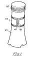
- Fig. 1 the neck 10 of a bottle, typically a sauce bottle is shown, and the top of the bottle is closed by means of a cap 12.
- a label 14 of the "full wrap” type in that the tabet ends 16 and 18 meet as shown in Fig. 1.
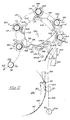
- FIG. 2 The mechanism and means for applying the labels 14tothe bottles 10 is shown in Fig. 2.
- reference numeral 20 represents the path which the bottles take when travelling through the machine, the direction of travel being indicated by arrows 22 the unlabelled bottles enter the application and wrapping device as shown at the region 24, and exit, duly labelled at region 26.
- Reference 28 represents a vacuum drum to which the labels 14 are held, the drum continuously rotating in the direction of arrow 30.
- the labels 14 are held to the drum periphery by means of a vacuum and are separated therefrom at location 34 where the bottles 10 moving in synchronism with the rotation of the drum come into tangential contact with the labels 14 as shown, so that each bottle 10 receives a label 14'so that the label 14 lies tangentially to the bottle neck, and so that the bottle neck contacts the label approximately in its mid region as shown at location 34.
- the labels are separated from the drum 28 by means of an air blowing system as described in an earlier European Patent Application, and then the air floated from the drum surface on to a paring knife 36.
- the bottles 10 thus carrying the labels 14 then move to a wrapping mechanism indicated generally by numeral 40 and the wrapping mechanism 40 comprises a rotary assembly carrying a plurality of wrapping arm assemblies 42 each comprising a pair of scissor like arms 44 and 46 respectively being a leading and trailing arm, and each comprising a roller follower 44A, 46A, and a wrapping roller 44B, and 46B.
- the arms are fitted together at pivot point 48, and are spring loaded together by means of a tension spring 49 and the portions of the arms carrying rollers 44B and 46B in the closed condition wrap around the bottle neck as shown clearly at location 50 in Fig. 2.
- the follower rollers 44A and 46A are adapted to engage the outer surfaces of fixed control cams 52 and 54 so that these respective cams control the opening and closing of the arms 44 and 46 during the rotational movement of the assemblies around the centre point 56.
- the two cams 52 and 54 are held stationary whilst a ring carrying the assemblies 42 is driven around the pivot point 56, so that the assemblies 42 move in an endless, circular path, and the rollers 44A and 46A remain in contact with the outer peripheries of the cams 52 and 54.
- the cam 52 has a lead ramp 58, followed by an arcuate raised cam portion 60 which leads to a trail ramp portion 62 and a lower arcuate portion 64 completes the cam profile.
- the cam 54 is provided with a lead ramp portion 66 leading to a raised cam portion 68 followed by a trail cam portion 70 leading to a lower arcuate portion 72 and then there is a bead portion 74 having a sharp elevating front 76 and an even sharper tail lowering portion 78, leading to a short lower arcuate portion 80 to complete the cam profile.
- the arms 44 and 46 pivot in sequence and this sequence is in order to effect opening and closing of the arms to permit respective bottles 10 with the labels 14 stuck thereto to be inserted between the arm portions carrying rollers 44B and 46B.
- the sequence of operations can be understood by examining the conditions of the arms at the respective locations 82, 84, 86, 88 and 90.
- the arm 44 is engaged upon the elevating track portion 58, and therefore has swung from the open position shown in Fig. 2.
- the bottle 10 with applied label 14 moving in path 20 is about to be entered between the arms 44 and 46.
- the arm 46 has by its follower roller 46A engaging the elevated arcuate portion 68 also pivoted to the open position and the bottle 10 has moved into location between the arms, but the ends of the label 14 engage the wiping rollers 44B and 46B, so that the label in fact takes up a V configuration as shown at location 84.
- the arm 44 has commenced closing by virtue of the fact that the follower 44A is engaged on lowering track portion 62, and therefore the appropriate side of the label 14 has been partially wrapped around the bottle neck, and by the time the assembly 42 has reached position 88, both arms 44 and 46 have moved to the closed position as shown at reference 50 in Fig. 2 completing the wrapping of the label around the bottle neck.
- the assembly travels in the closed position until it reaches location 90 whereat the arm 46 has opened sharply permitting the bottle 10 with the label 14 wrapped therearound to move out of the assembly and to location 26.
- the retention member 92 shown in Fig. 2 is to assist in forcing the bottles into location between the open arms 44 and 46 of each assembly 42.
Landscapes
- Engineering & Computer Science (AREA)
- Mechanical Engineering (AREA)
- Labeling Devices (AREA)
- Auxiliary Devices For And Details Of Packaging Control (AREA)
- Beans For Foods Or Fodder (AREA)
- Making Paper Articles (AREA)
- Adhesives Or Adhesive Processes (AREA)
- Die Bonding (AREA)
Abstract
Description
- According to the preamble of
claim 1 this invention relates to a machine for the application of labels to articles, and particularly concerns the application of labels to articles which are in the nature of containers containing for example liquids such as cosmetics, foodstuffs, condiments or beverages. - Although the invention has application to the containers mentioned, it is to be understood that invention is not to be limited to specific containers or container contents but can be applied to a wide range of articles provided that such articles are of appropriate geometric shape, as will follow from the disclosure herein.
- The present invention was conceived arising from a need to apply labels to the necks of bottles, in particular sauce bottles, and in the interests of simplicity reference will be made hereinafter only to the application of labels to the necks of sauce bottles.
- The labels in connection with which the invention is to be applied will normally have an adhesive surface on one side thereof, being the side which is applied to the bottle neck, although it should be mentioned that the invention may be applicable where the mechanical inversion applies i.e. where the adhesive is on the bottle neck, and the label is applied thereto, but again in the interests of simplicity of explanation, only the case in which the adhesive is on the label will be discussed and referred to.
- Finally, the invention is applicable to a situation in which the bottles whose necks are to be labelled travel in sequence through an applicator machine i.e. the process is automated to ensure high speed and efficient production.
- In one known method of applying labels to bottle necks which is described in European Patent Application No. 0078076, the adhesive side of the label, by a leading end thereof, is applied to the bottle neck, and then the bottle, whilst it moves through the machine, is caused to rotate so that the label is wiped around the neck surface and adheres thereto. The label may be what is known as a complete wrap round label in which case the trailing end of the label meets or overlaps the leading end when it has been wrapped round the bottle neck, or it may be a patch label which extends only part way around the bottle neck.
- This method of applying bottle neck labels is expensive and slow insofar as a means is needed to revolve the bottles, and a finite time is also required to ensure that the bottle effects a complete rotation.
- Additionally, the known method typically uses pressure sensitive adhesives which are carried by a release carrier web so that the labels can be peeled from the web and applied to the bottles, but more recently there has been developed technology for cutting individual labels from a roll of backingless self adhesive labels, the labels being cut from the web which moves continuously through the label applicator machine by a suitable label cutting mechanism embodied in a label applicator machine. Such labels when cut from the web are held by a vacuum drum, with the adhesive side facing outwards, and from this drum they have to be applied to the bottle necks. The conventional method of applying the leading edge of the label to the bottle neck followed by a spinning of the bottle cannot be adopted in such circumstances.
- Also known devices for applying labels to bottle necks are disclosed in United States Patent 3,616,092, European Patent Applications Nos. 0135935 and British Patent Nos. 1,080,370 and 927147.
- In particular U.S. Patent 3,616,092 discloses that labels are wrapped around bottle necks after the labels have been applied in flat condition and tangentially to side necks in that the bottles are moved through the machine in a step by step sequence. At a first position, the labels are applied to the bottle necks, and then the bottles are moved to a second position. At the second position, a deflecting mechanism advances and partially applies a label around the bottle neck whereupon the bottle is moved to a further station. At the further station, the label is fully wrapped round the neck by scissor like arms which advance on a sliding member and the movement of the scissor like arms is controlled by a complicated arrangement of springs and labels. Such a machine is particularly complex and is relatively slow in operation insofar as the bottles must move on a step by step pattern.
- British Patent No. 927147 discloses a labelling machine in which bottles move along a straight path wherein labels are applied tangentially to their necks and brushed around their sides. The bottles are then pushed radially into a pocket between the arms of a wrapping assembly carried on a carousel. A camming means causes the arms to close and wrap the label around the bottle and then to open and release the bottle. The radial movement of the bottle into the pocket necessitates an intermittent motion and the brushing of the labels round the sides of the bottles also slows down the labelling process.
- The present invention differs from the prior art in that it achieves a continuous process which rapidly and accuratley wraps the labels around the necks of the bottles.
- According to the second part of
claim 1 the machine for applying labels to bottles is characterised in that the means for moving bottles in sequence is arranged to feed bottles individually into pockets of said arm assemblies in a direction tangentially to said endless path while the said assemblies move in the endless path so that the bottles are progressively fed into the pockets, such progressive feeding causing partial wrapping of the labels round the bottles and so that said cam means operate said arm assemblies by virtue of the movement of the assemblies around said endless path to complete the wrapping of the labels around the bottles. - Preferably the said arm assemblies comprise arcuate arms carrying cam rollers at the extremities thereof, said rollers being caused to roll around the bottle to apply respective portions of the label extending to each side of where the label contacts the bottle tangentially. The means for moving preferably comprises a carousel wheel having pockets in which the bottles are individually located, the arm assemblies being operated in sequence with the movement of the bottles by virtue of a further camming arrangement between said arm assemblies and fixed cams of the machine.
- The two arms of each pair may move differently insofar as a first arm, the leading arm, which is initially contacted by the bottle and label may be caused to move in advance of the second or trailing arm, initially to effect wrapping of the leading portion of the label around the bottle, followed by actuation of the second arm which is accelerated to a greater extent to effect the wrapping of the trailing portion on the label.
- When the machine through which the bottles pass is provided with a vacuum drum for holding individual labels thereto, preferably the leading end of each label is blown away from the drum, and such leading end travels over a plate guide in order to slice the labels individually away from the vacuum drum as such drum rotates. At the same time, the bottle comes into contact tangentially with the central region of the label, and the bottle and the thus applied label travel to the arm assembly by said means for moving.
- The said rollers may be provided with soft flexible outer surfaces for effecting the wiping of the label around a bottle neck, and so as not to damage the labels, or the outer surfaces may simply be defined by rubber rollers. The said rollers will of course be rotatably mounted on the said cam arms.
- The carousel will of course be provided with a plurality of pockets so as to receive the bottles in sequence, each pocket being associated with a piar of said camming arms and rollers.
- Preferably, the machine has die and anvil means for cutting out the labels from a web of backingless adhesive labels. The adhesive preferably is on the labels, and preferably is of the pressure sensitive type, although a heat sensitive type may be used, in which case it would be desirable to provide a heat activating means within the applicator machinery in order to activate the adhesive before the labels are applied to the bottles.
- In practice, a high tack adhesive is used to ensure that the labels will remain tangentially connected to the bottle necks as the bottles move between the location where the labels are attached to the bottles tangentially, and where the labels are finally wrapped completely on the bottle neck.
- It will be understood that the invention can be applied to complete wrap around labels or patch labels, and it will also be understood clearlythat it is not necessary that the labels be applied to bottles or bottle necks as clearly the principle can be applied in any circumstance where a label is to be wrapped round an article, which may be a box or can, as opposed simply to be stuck on a flat face of the article.
- An embodiment of the present invention will now be described, by way of example, with reference to the accompanying drawings, wherein:-
- Fig. 1 is a perspective view of a bottle neck; and
- Fig. 2 is a diagrammatic plan showing the mechanism and means for applying the label to the bottle neck as shown in Fig. 1.
- Referring to the drawings, in Fig. 1 the
neck 10 of a bottle, typically a sauce bottle is shown, and the top of the bottle is closed by means of acap 12. Around the bottle neck is applied alabel 14 of the "full wrap" type in that the tabet ends 16 and 18 meet as shown in Fig. 1. - The mechanism and means for applying the
labels 14tothe bottles 10 is shown in Fig. 2. In Fig. 2, reference numeral 20 represents the path which the bottles take when travelling through the machine, the direction of travel being indicated byarrows 22 the unlabelled bottles enter the application and wrapping device as shown at the region 24, and exit, duly labelled atregion 26. -
Reference 28 represents a vacuum drum to which thelabels 14 are held, the drum continuously rotating in the direction of arrow 30. Thelabels 14 are held to the drum periphery by means of a vacuum and are separated therefrom atlocation 34 where thebottles 10 moving in synchronism with the rotation of the drum come into tangential contact with thelabels 14 as shown, so that eachbottle 10 receives a label 14'so that thelabel 14 lies tangentially to the bottle neck, and so that the bottle neck contacts the label approximately in its mid region as shown atlocation 34. - The labels are separated from the
drum 28 by means of an air blowing system as described in an earlier European Patent Application, and then the air floated from the drum surface on to aparing knife 36. Thebottles 10 thus carrying thelabels 14 then move to a wrapping mechanism indicated generally by numeral 40 and the wrapping mechanism 40 comprises a rotary assembly carrying a plurality ofwrapping arm assemblies 42 each comprising a pair of scissor likearms 44 and 46 respectively being a leading and trailing arm, and each comprising aroller follower 44A, 46A, and awrapping roller 44B, and 46B. The arms are fitted together at pivot point 48, and are spring loaded together by means of atension spring 49 and the portions of thearms carrying rollers 44B and 46B in the closed condition wrap around the bottle neck as shown clearly atlocation 50 in Fig. 2. Thefollower rollers 44A and 46A are adapted to engage the outer surfaces of fixed control cams 52 and 54 so that these respective cams control the opening and closing of thearms 44 and 46 during the rotational movement of the assemblies around thecentre point 56. - The two cams 52 and 54 are held stationary whilst a ring carrying the
assemblies 42 is driven around thepivot point 56, so that theassemblies 42 move in an endless, circular path, and therollers 44A and 46A remain in contact with the outer peripheries of the cams 52 and 54. - The cam 52 has a
lead ramp 58, followed by an arcuate raised cam portion 60 which leads to atrail ramp portion 62 and a lower arcuate portion 64 completes the cam profile. - The cam 54 is provided with a lead ramp portion 66 leading to a raised cam portion 68 followed by a trail cam portion 70 leading to a lower
arcuate portion 72 and then there is abead portion 74 having a sharpelevating front 76 and an even sharpertail lowering portion 78, leading to a short lower arcuate portion 80 to complete the cam profile. - As will be understood, as the
assemblies 42 are rotated round the cams 52 and 54, so thearms 44 and 46 pivot in sequence and this sequence is in order to effect opening and closing of the arms to permitrespective bottles 10 with thelabels 14 stuck thereto to be inserted between the armportions carrying rollers 44B and 46B. The sequence of operations can be understood by examining the conditions of the arms at therespective locations - At
location 82, the arm 44 is engaged upon theelevating track portion 58, and therefore has swung from the open position shown in Fig. 2. At the same time thebottle 10 with appliedlabel 14 moving in path 20 is about to be entered between thearms 44 and 46. - At location 84, the
arm 46 has by itsfollower roller 46A engaging the elevated arcuate portion 68 also pivoted to the open position and thebottle 10 has moved into location between the arms, but the ends of thelabel 14 engage thewiping rollers 44B and 46B, so that the label in fact takes up a V configuration as shown at location 84. - By the time location 86 has been reached, the arm 44 has commenced closing by virtue of the fact that the follower 44A is engaged on lowering
track portion 62, and therefore the appropriate side of thelabel 14 has been partially wrapped around the bottle neck, and by the time theassembly 42 has reachedposition 88, botharms 44 and 46 have moved to the closed position as shown atreference 50 in Fig. 2 completing the wrapping of the label around the bottle neck. The assembly travels in the closed position until it reacheslocation 90 whereat thearm 46 has opened sharply permitting thebottle 10 with thelabel 14 wrapped therearound to move out of the assembly and tolocation 26. - The process if of course synchronized in that the bottles move in synchronism with the rotation of the
ring carrying assemblies 42 so that high speed and effective labelling can take place. - It will be noticed that there is no requirement for the bottle to be rotated about its own axis during the application of the label in the method as illustrated in Fig. 2.
- It will be understood furthermore that the invention is applicable to the labelling of articles other than bottles.
- The
retention member 92 shown in Fig. 2 is to assist in forcing the bottles into location between theopen arms 44 and 46 of eachassembly 42.
Claims (8)
Priority Applications (1)
| Application Number | Priority Date | Filing Date | Title |
|---|---|---|---|
| AT87103495T ATE54888T1 (en) | 1986-03-18 | 1987-03-11 | APPLYING LABELS TO ITEMS. |
Applications Claiming Priority (2)
| Application Number | Priority Date | Filing Date | Title |
|---|---|---|---|
| GB8606629 | 1986-03-18 | ||
| GB868606629A GB8606629D0 (en) | 1986-03-18 | 1986-03-18 | Application of labels to articles |
Publications (2)
| Publication Number | Publication Date |
|---|---|
| EP0241709A1 EP0241709A1 (en) | 1987-10-21 |
| EP0241709B1 true EP0241709B1 (en) | 1990-07-25 |
Family
ID=10594789
Family Applications (1)
| Application Number | Title | Priority Date | Filing Date |
|---|---|---|---|
| EP87103495A Expired - Lifetime EP0241709B1 (en) | 1986-03-18 | 1987-03-11 | Improvements relating to the application of labels to articles |
Country Status (8)
| Country | Link |
|---|---|
| US (1) | US4793891A (en) |
| EP (1) | EP0241709B1 (en) |
| JP (1) | JPH0725378B2 (en) |
| AT (1) | ATE54888T1 (en) |
| AU (1) | AU594132B2 (en) |
| CA (1) | CA1296298C (en) |
| DE (1) | DE3763880D1 (en) |
| GB (1) | GB8606629D0 (en) |
Families Citing this family (11)
| Publication number | Priority date | Publication date | Assignee | Title |
|---|---|---|---|---|
| US5421933A (en) * | 1992-12-23 | 1995-06-06 | Graydon Wesley Nedblake | System for producing labels from a web |
| US5705024A (en) * | 1995-09-28 | 1998-01-06 | Becton, Dickinson And Company | System for application of labels |
| US5855710A (en) * | 1996-11-12 | 1999-01-05 | Trine Labeling Systems | Method and apparatus for labeling containers |
| US5858168A (en) * | 1997-02-03 | 1999-01-12 | Trine Labeling Systems | Method and apparatus using enhanced air blow for labeling containers |
| US7704347B2 (en) * | 2005-05-27 | 2010-04-27 | Prairie Packaging, Inc. | Reinforced plastic foam cup, method of and apparatus for manufacturing same |
| US7814647B2 (en) | 2005-05-27 | 2010-10-19 | Prairie Packaging, Inc. | Reinforced plastic foam cup, method of and apparatus for manufacturing same |
| US7818866B2 (en) | 2005-05-27 | 2010-10-26 | Prairie Packaging, Inc. | Method of reinforcing a plastic foam cup |
| US7694843B2 (en) | 2005-05-27 | 2010-04-13 | Prairie Packaging, Inc. | Reinforced plastic foam cup, method of and apparatus for manufacturing same |
| DE102006038249A1 (en) * | 2006-08-16 | 2008-02-21 | Khs Ag | Method for circumferentially labeling containers |
| US8828170B2 (en) | 2010-03-04 | 2014-09-09 | Pactiv LLC | Apparatus and method for manufacturing reinforced containers |
| MX2022015960A (en) * | 2020-06-15 | 2023-01-24 | Anheuser Busch Llc | Full wrap pressure sensitive label. |
Citations (2)
| Publication number | Priority date | Publication date | Assignee | Title |
|---|---|---|---|---|
| GB927147A (en) * | 1961-02-21 | 1963-05-29 | Morgan Fairest Ltd | Improvements in or relating to labelling machines |
| DE1297530B (en) * | 1961-02-09 | 1969-06-12 | Canadian Stackpole Ltd | Pressure device for labels for bottles or containers |
Family Cites Families (7)
| Publication number | Priority date | Publication date | Assignee | Title |
|---|---|---|---|---|
| US1536837A (en) * | 1924-04-05 | 1925-05-05 | Fredsell Charles Ragnar | Label-wiping station |
| GB871031A (en) * | 1957-12-10 | 1961-06-21 | Embossed Metal Products Inc | Improvements in or relating to a bottle processing machine |
| US3616092A (en) * | 1969-10-22 | 1971-10-26 | Michael Albert Lavigne | Neck wrap apparatus |
| CA1155806A (en) * | 1978-12-05 | 1983-10-25 | Martin Malthouse | Labelling equipment |
| EP0018457B1 (en) * | 1978-12-05 | 1984-05-16 | Associpak International Inc. | Labelling equipment |
| JPS5717782A (en) * | 1980-06-24 | 1982-01-29 | Kayaba Industry Co Ltd | Hatch for high pressure tank |
| GB2147264B (en) * | 1983-09-29 | 1987-04-15 | Metal Box Plc | Label wrapping machines |
-
1986
- 1986-03-18 GB GB868606629A patent/GB8606629D0/en active Pending
-
1987
- 1987-03-11 AT AT87103495T patent/ATE54888T1/en active
- 1987-03-11 DE DE8787103495T patent/DE3763880D1/en not_active Expired - Fee Related
- 1987-03-11 EP EP87103495A patent/EP0241709B1/en not_active Expired - Lifetime
- 1987-03-16 CA CA000532130A patent/CA1296298C/en not_active Expired - Lifetime
- 1987-03-18 JP JP62063638A patent/JPH0725378B2/en not_active Expired - Fee Related
- 1987-03-18 AU AU70116/87A patent/AU594132B2/en not_active Ceased
- 1987-03-18 US US07/027,374 patent/US4793891A/en not_active Expired - Fee Related
Patent Citations (2)
| Publication number | Priority date | Publication date | Assignee | Title |
|---|---|---|---|---|
| DE1297530B (en) * | 1961-02-09 | 1969-06-12 | Canadian Stackpole Ltd | Pressure device for labels for bottles or containers |
| GB927147A (en) * | 1961-02-21 | 1963-05-29 | Morgan Fairest Ltd | Improvements in or relating to labelling machines |
Also Published As
| Publication number | Publication date |
|---|---|
| ATE54888T1 (en) | 1990-08-15 |
| JPH0725378B2 (en) | 1995-03-22 |
| US4793891A (en) | 1988-12-27 |
| GB8606629D0 (en) | 1986-04-23 |
| CA1296298C (en) | 1992-02-25 |
| AU594132B2 (en) | 1990-03-01 |
| JPS62271830A (en) | 1987-11-26 |
| DE3763880D1 (en) | 1990-08-30 |
| AU7011687A (en) | 1987-09-24 |
| EP0241709A1 (en) | 1987-10-21 |
Similar Documents
| Publication | Publication Date | Title |
|---|---|---|
| EP0241709B1 (en) | Improvements relating to the application of labels to articles | |
| CA2271141C (en) | Roll-fed labelling apparatus | |
| US4108709A (en) | Label applying machine | |
| US4108710A (en) | Apparatus for applying labels to containers | |
| US5491010A (en) | Container with a label adhered to the container | |
| US6328832B1 (en) | Labeling apparatus with web registration, web cutting and carrier mechanisms, and methods thereof | |
| US5116452A (en) | Device for applying labels to containers | |
| US4931122A (en) | Straight through labelling machine | |
| US4910941A (en) | Method and apparatus for fitting a tube on a container or the like | |
| US4724029A (en) | Method and apparatus for applying a flexible plastic label to a round container | |
| US4724036A (en) | Progressively ported vacuum drum for labeling machines | |
| US4562684A (en) | Apparatus for applying a tubular member over a container | |
| CA2074921C (en) | Cylindrical body label wrapping system with cam operated adjustable path length retractable heaters | |
| US3450591A (en) | Apparatus for the labeling of bottles and other articles | |
| EP0450821B1 (en) | Labeling machine and method | |
| US4671843A (en) | Label transport vacuum drum | |
| EP0059202A1 (en) | Cable drive turret for decoration of articles | |
| NZ217649A (en) | Roll for applying solvent to plastics roll-on bottle label | |
| EP0624522B1 (en) | Labelling machine | |
| CA1044656A (en) | Labelling station in a labelling machine | |
| JPH0253297B2 (en) | ||
| US3159522A (en) | Apparatus for labeling bodies, particularly bottles in upright position | |
| US4090913A (en) | Label transfer system for a labeling station | |
| FR2370682A1 (en) | Endless chain bottle filling machine - has intermittently operated filler turntable and label applicator driven by common continuous drive | |
| WO1998014375A1 (en) | Labelling apparatus |
Legal Events
| Date | Code | Title | Description |
|---|---|---|---|
| PUAI | Public reference made under article 153(3) epc to a published international application that has entered the european phase |
Free format text: ORIGINAL CODE: 0009012 |
|
| AK | Designated contracting states |
Kind code of ref document: A1 Designated state(s): AT BE CH DE ES FR GB GR IT LI NL SE |
|
| 17P | Request for examination filed |
Effective date: 19871109 |
|
| 17Q | First examination report despatched |
Effective date: 19890224 |
|
| GRAA | (expected) grant |
Free format text: ORIGINAL CODE: 0009210 |
|
| AK | Designated contracting states |
Kind code of ref document: B1 Designated state(s): AT BE CH DE ES FR GB GR IT LI NL SE |
|
| PG25 | Lapsed in a contracting state [announced via postgrant information from national office to epo] |
Ref country code: IT Free format text: LAPSE BECAUSE OF FAILURE TO SUBMIT A TRANSLATION OF THE DESCRIPTION OR TO PAY THE FEE WITHIN THE PRE;WARNING: LAPSES OF ITALIAN PATENTS WITH EFFECTIVE DATE BEFORE 2007 MAY HAVE OCCURRED AT ANY TIME BEFORE 2007. THE CORRECT EFFECTIVE DATE MAY BE DIFFERENT FROM THE ONE RECORDED.SCRIBED TIME-LIMIT Effective date: 19900725 Ref country code: LI Effective date: 19900725 Ref country code: NL Effective date: 19900725 Ref country code: AT Effective date: 19900725 Ref country code: SE Effective date: 19900725 Ref country code: FR Effective date: 19900725 Ref country code: GR Free format text: LAPSE BECAUSE OF FAILURE TO SUBMIT A TRANSLATION OF THE DESCRIPTION OR TO PAY THE FEE WITHIN THE PRESCRIBED TIME-LIMIT Effective date: 19900725 Ref country code: BE Effective date: 19900725 Ref country code: CH Effective date: 19900725 |
|
| REF | Corresponds to: |
Ref document number: 54888 Country of ref document: AT Date of ref document: 19900815 Kind code of ref document: T |
|
| REF | Corresponds to: |
Ref document number: 3763880 Country of ref document: DE Date of ref document: 19900830 |
|
| PG25 | Lapsed in a contracting state [announced via postgrant information from national office to epo] |
Ref country code: ES Free format text: LAPSE BECAUSE OF FAILURE TO SUBMIT A TRANSLATION OF THE DESCRIPTION OR TO PAY THE FEE WITHIN THE PRESCRIBED TIME-LIMIT Effective date: 19901105 |
|
| REG | Reference to a national code |
Ref country code: CH Ref legal event code: PL |
|
| EN | Fr: translation not filed | ||
| NLV1 | Nl: lapsed or annulled due to failure to fulfill the requirements of art. 29p and 29m of the patents act | ||
| PLBE | No opposition filed within time limit |
Free format text: ORIGINAL CODE: 0009261 |
|
| STAA | Information on the status of an ep patent application or granted ep patent |
Free format text: STATUS: NO OPPOSITION FILED WITHIN TIME LIMIT |
|
| 26N | No opposition filed | ||
| PG25 | Lapsed in a contracting state [announced via postgrant information from national office to epo] |
Ref country code: DE Effective date: 19920101 |
|
| PGFP | Annual fee paid to national office [announced via postgrant information from national office to epo] |
Ref country code: GB Payment date: 19950106 Year of fee payment: 9 |
|
| PG25 | Lapsed in a contracting state [announced via postgrant information from national office to epo] |
Ref country code: GB Effective date: 19960311 |
|
| GBPC | Gb: european patent ceased through non-payment of renewal fee |
Effective date: 19960311 |