EP0241607B1 - Chromatographisches Verfahren zur Feststellung der Verschmutzungsfähigkeit von flüssigen Kohlenwasserstoffverbindungen - Google Patents
Chromatographisches Verfahren zur Feststellung der Verschmutzungsfähigkeit von flüssigen Kohlenwasserstoffverbindungen Download PDFInfo
- Publication number
- EP0241607B1 EP0241607B1 EP86302800A EP86302800A EP0241607B1 EP 0241607 B1 EP0241607 B1 EP 0241607B1 EP 86302800 A EP86302800 A EP 86302800A EP 86302800 A EP86302800 A EP 86302800A EP 0241607 B1 EP0241607 B1 EP 0241607B1
- Authority
- EP
- European Patent Office
- Prior art keywords
- hydrocarbon
- sample
- fouling
- tendency
- crude
- Prior art date
- Legal status (The legal status is an assumption and is not a legal conclusion. Google has not performed a legal analysis and makes no representation as to the accuracy of the status listed.)
- Expired - Lifetime
Links
- 229930195733 hydrocarbon Natural products 0.000 title claims description 47
- 150000002430 hydrocarbons Chemical class 0.000 title claims description 47
- 239000007788 liquid Substances 0.000 title claims description 24
- 238000004587 chromatography analysis Methods 0.000 title 1
- 239000004215 Carbon black (E152) Substances 0.000 claims description 44
- 238000000034 method Methods 0.000 claims description 25
- 239000011159 matrix material Substances 0.000 claims description 13
- 238000013375 chromatographic separation Methods 0.000 claims description 11
- VYPSYNLAJGMNEJ-UHFFFAOYSA-N Silicium dioxide Chemical compound O=[Si]=O VYPSYNLAJGMNEJ-UHFFFAOYSA-N 0.000 claims description 10
- 239000000463 material Substances 0.000 claims description 9
- 239000000741 silica gel Substances 0.000 claims description 7
- 229910002027 silica gel Inorganic materials 0.000 claims description 7
- 239000010408 film Substances 0.000 claims description 5
- 239000002904 solvent Substances 0.000 claims description 5
- 238000000151 deposition Methods 0.000 claims description 4
- 239000010409 thin film Substances 0.000 claims description 4
- 230000002378 acidificating effect Effects 0.000 claims description 3
- 230000003373 anti-fouling effect Effects 0.000 claims description 3
- 239000002519 antifouling agent Substances 0.000 claims description 3
- PNEYBMLMFCGWSK-UHFFFAOYSA-N aluminium oxide Inorganic materials [O-2].[O-2].[O-2].[Al+3].[Al+3] PNEYBMLMFCGWSK-UHFFFAOYSA-N 0.000 claims description 2
- 238000001179 sorption measurement Methods 0.000 claims 1
- 239000010779 crude oil Substances 0.000 description 42
- 239000003921 oil Substances 0.000 description 16
- 238000004809 thin layer chromatography Methods 0.000 description 15
- 238000012360 testing method Methods 0.000 description 14
- 239000012530 fluid Substances 0.000 description 10
- 238000012986 modification Methods 0.000 description 8
- 230000004048 modification Effects 0.000 description 8
- 239000002609 medium Substances 0.000 description 6
- 238000000926 separation method Methods 0.000 description 6
- 238000012546 transfer Methods 0.000 description 6
- 229910052751 metal Inorganic materials 0.000 description 5
- 239000002184 metal Substances 0.000 description 5
- 239000000126 substance Substances 0.000 description 5
- 238000005259 measurement Methods 0.000 description 4
- 239000002594 sorbent Substances 0.000 description 4
- IMNFDUFMRHMDMM-UHFFFAOYSA-N N-Heptane Chemical compound CCCCCCC IMNFDUFMRHMDMM-UHFFFAOYSA-N 0.000 description 3
- 239000012501 chromatography medium Substances 0.000 description 3
- 230000007423 decrease Effects 0.000 description 3
- 238000013508 migration Methods 0.000 description 3
- 230000005012 migration Effects 0.000 description 3
- VLKZOEOYAKHREP-UHFFFAOYSA-N n-Hexane Chemical compound CCCCCC VLKZOEOYAKHREP-UHFFFAOYSA-N 0.000 description 3
- 239000000654 additive Substances 0.000 description 2
- 230000015572 biosynthetic process Effects 0.000 description 2
- ZOMBKNNSYQHRCA-UHFFFAOYSA-J calcium sulfate hemihydrate Chemical compound O.[Ca+2].[Ca+2].[O-]S([O-])(=O)=O.[O-]S([O-])(=O)=O ZOMBKNNSYQHRCA-UHFFFAOYSA-J 0.000 description 2
- 238000010790 dilution Methods 0.000 description 2
- 239000012895 dilution Substances 0.000 description 2
- 239000011521 glass Substances 0.000 description 2
- NHTMVDHEPJAVLT-UHFFFAOYSA-N Isooctane Chemical compound CC(C)CC(C)(C)C NHTMVDHEPJAVLT-UHFFFAOYSA-N 0.000 description 1
- 239000005909 Kieselgur Substances 0.000 description 1
- 239000002250 absorbent Substances 0.000 description 1
- 230000002745 absorbent Effects 0.000 description 1
- 230000001133 acceleration Effects 0.000 description 1
- 230000000996 additive effect Effects 0.000 description 1
- 229910052782 aluminium Inorganic materials 0.000 description 1
- XAGFODPZIPBFFR-UHFFFAOYSA-N aluminium Chemical compound [Al] XAGFODPZIPBFFR-UHFFFAOYSA-N 0.000 description 1
- 238000004458 analytical method Methods 0.000 description 1
- 238000013459 approach Methods 0.000 description 1
- 239000011230 binding agent Substances 0.000 description 1
- 238000009529 body temperature measurement Methods 0.000 description 1
- OSGAYBCDTDRGGQ-UHFFFAOYSA-L calcium sulfate Inorganic materials [Ca+2].[O-]S([O-])(=O)=O OSGAYBCDTDRGGQ-UHFFFAOYSA-L 0.000 description 1
- 239000001913 cellulose Substances 0.000 description 1
- 229920002678 cellulose Polymers 0.000 description 1
- 238000005119 centrifugation Methods 0.000 description 1
- 239000003245 coal Substances 0.000 description 1
- 239000011248 coating agent Substances 0.000 description 1
- 238000000576 coating method Methods 0.000 description 1
- 238000004939 coking Methods 0.000 description 1
- 238000010835 comparative analysis Methods 0.000 description 1
- 230000002596 correlated effect Effects 0.000 description 1
- 230000002939 deleterious effect Effects 0.000 description 1
- 230000008021 deposition Effects 0.000 description 1
- JVSWJIKNEAIKJW-UHFFFAOYSA-N dimethyl-hexane Natural products CCCCCC(C)C JVSWJIKNEAIKJW-UHFFFAOYSA-N 0.000 description 1
- 239000002270 dispersing agent Substances 0.000 description 1
- 238000004821 distillation Methods 0.000 description 1
- 230000000694 effects Effects 0.000 description 1
- 238000005516 engineering process Methods 0.000 description 1
- 238000011156 evaluation Methods 0.000 description 1
- 239000011888 foil Substances 0.000 description 1
- 239000000446 fuel Substances 0.000 description 1
- 108010025899 gelatin film Proteins 0.000 description 1
- 239000011507 gypsum plaster Substances 0.000 description 1
- 238000009533 lab test Methods 0.000 description 1
- 239000002985 plastic film Substances 0.000 description 1
- 230000001376 precipitating effect Effects 0.000 description 1
- 238000001556 precipitation Methods 0.000 description 1
- 238000012545 processing Methods 0.000 description 1
- 238000007670 refining Methods 0.000 description 1
- RMAQACBXLXPBSY-UHFFFAOYSA-N silicic acid Chemical compound O[Si](O)(O)O RMAQACBXLXPBSY-UHFFFAOYSA-N 0.000 description 1
- 235000012239 silicon dioxide Nutrition 0.000 description 1
- 238000004088 simulation Methods 0.000 description 1
- 238000010998 test method Methods 0.000 description 1
Images
Classifications
-
- G—PHYSICS
- G01—MEASURING; TESTING
- G01N—INVESTIGATING OR ANALYSING MATERIALS BY DETERMINING THEIR CHEMICAL OR PHYSICAL PROPERTIES
- G01N30/00—Investigating or analysing materials by separation into components using adsorption, absorption or similar phenomena or using ion-exchange, e.g. chromatography or field flow fractionation
- G01N30/90—Plate chromatography, e.g. thin layer or paper chromatography
-
- G—PHYSICS
- G01—MEASURING; TESTING
- G01N—INVESTIGATING OR ANALYSING MATERIALS BY DETERMINING THEIR CHEMICAL OR PHYSICAL PROPERTIES
- G01N33/00—Investigating or analysing materials by specific methods not covered by groups G01N1/00 - G01N31/00
- G01N33/26—Oils; Viscous liquids; Paints; Inks
- G01N33/28—Oils, i.e. hydrocarbon liquids
- G01N33/2805—Oils, i.e. hydrocarbon liquids investigating the resistance to heat or oxidation
-
- Y—GENERAL TAGGING OF NEW TECHNOLOGICAL DEVELOPMENTS; GENERAL TAGGING OF CROSS-SECTIONAL TECHNOLOGIES SPANNING OVER SEVERAL SECTIONS OF THE IPC; TECHNICAL SUBJECTS COVERED BY FORMER USPC CROSS-REFERENCE ART COLLECTIONS [XRACs] AND DIGESTS
- Y10—TECHNICAL SUBJECTS COVERED BY FORMER USPC
- Y10T—TECHNICAL SUBJECTS COVERED BY FORMER US CLASSIFICATION
- Y10T436/00—Chemistry: analytical and immunological testing
- Y10T436/21—Hydrocarbon
Definitions
- the present invention relates to a test method for determining the tendency of liquid hydrocarbon streams to foul equipment and more particularly to a method for determining oil-asphaltenes incompatibility and related fouling tendency.
- test unit which is configured to allow measurement of the fluid temperature at the exit of the heat-exchanger while the metal temperature of the heated tube is controlled.
- This configuration provides for close simulation of refinery and petrochemical plant heat-exchanger operations and provides for measurement of the significant effect of fouling which is indicated by the reduction of heat transfer.
- the test unit provides for a thermal fouling evaluation of the crude oil in an accelerated test which is designed to reproduce the fouling problem experienced in a refinery over several months. Acceleration is provided by carrying out test operating temperatures higher than those in a particular refinery unit, so that the prospective level of fouling can be produced in a reasonable period of time (usually 3--4 hours).
- Heat transfer data is obtained by holding the heater tube at a constant temperature, while measuring the change in the liquid outlet temperature. As fouling progresses, i.e., a carbonaceous deposit build up on the heater tube surface, a decrease in the fluid outlet temperature results when using a constant outlet liquid temperature operation.
- the change in liquid outlet temperature with time provides the basic heat data required for comparative evaluation of untreated material and additive-treated material.
- the rate of change in outlet liquid temperature versus time shows relative fouling tendencies.
- a method for determining the tendency of oil containing asphaltenes to foul refinery equipment comprising the step of chromatographically separating said oil within a medium into respective light fractions and asphaltenes, whereby said tendency of said crude oil to foul said refinery equipment is visually indicated by a distinct demarcation between light fractions and said asphaltenes fraction.
- Hydrocarbon streams used in refinery operations, in particular, crude oils, are composed of two major parts; high molecular weight asphaltene (fraction insolubles in paraffinic solvents) and a lower molecular weight asphaltene-free oil.
- the asphaltene and the oil fraction vary significantly in their chemical structure, coking characteristics, thermal characteristics, average molecular weight and distribution.
- Table I illustrates the varying differences in the characteristics of a typical heavy hydrocarbon, its asphaltene and oil fractions:
- Asphaltenes present in heavy hydrocarbons have high molecular weight and very broad molecular weight distribution, sometimes with molecular weights up to 10,000.
- the invention uses Thin Layer Chromatography (TLC) to separate the high molecular weight asphaltenes and the low molecular weight crude oil fractions.
- TLC Thin Layer Chromatography
- Thin layer chromatography is a well known technique as described in a book by Joseph C. Touchstone and M. F. Dobbins, entitled: "Practice of Thin Layer Chromatography", published by Wiley-Interscience, 1978.
- Thin layer chromatography is a separation method in which uniform thin layers of selected sorbent media are used as a carrier medium.
- the sorbent is applied to a backing as a coating to obtain a stable layer of suitable size.
- the most common support is a glass plate, but other supports such as plastic sheets and aluminum foil are also used.
- the four sorbents most commonly used are silica gel, alumina, kieselguhr (diatomaceous earth), and cellulose.
- Silica gel sicic acid
- a binding agent such as plaster of paris (calcium sulfate hemihydrate) is commonly used. Separation can be accomplished in less than an hour at a very reasonable cost.
- Fouling tendencies of the crude oil are indicated in the chromatographic medium by extreme differences in the migration of the molecularly light and heavy fractions. These differences are shown by a clear demarcation between visually light and dark areas. Where heavy asphaltene fractions are incompatible with the lighter matrix oil, a distinct dark colored ring or disk is formed as a result of the outward migration of the crude oil from the point of its deposition onto the chromatographic medium.
- the invention features a method for predicting the fouling tendency of a crude oil to foul refinery equipment using the TLC techniques with a specific absorbent medium.
- the crude oil is separated in a thin sorbent medium into respective molecularly light and heavy (asphaltenes) fractions, which are characterized by visually light and dark areas within the medium.
- the tendency of the crude oil to cause fouling in the refinery equipment is indicated by a visually distinct demarcation between the light and dark areas which dark area appears as a ring or disk.
- a drop of the hydrocarbon stream to be tested is deposited on and thereby introduced into the thin layer chromatographic medium and fractionated by allowing the various fractions to migrate for a time sufficient to produce distinct demarcations between them.
- the formation of a dark brown or black ring in the center of the medium will indicate the presence of incompatible high molecular weight asphaltenes which will have a tendency to cause fouling in conventional oil refinery operations.
- the use of thin layer chromatography to separate the fractions of various fouling and non-fouling crude oils to identify the oil-asphaltene incompatibility provides a method capable of predicting by a quick and inexpensive test when a particular crude oil would foul the refinery equipment.
- This method of the invention can be corroborated by thereafter determining which crude oils have a tendency to cause fouling by the Thermal Fouling Tester (an apparatus widely used in the industry to measure the fouling tendencies of crude oils and other hydrocarbon streams). Chromatograms of the various crude oils have been made, and the results of these chromatograms thereafter correlated to the known fouling characteristics of each crude oil.
- the Tester is a modification of the Alco Tester described in ASTM Vol. 50 D-3241. It is configured to allow measurement of the fluid temperature at the exit of the heat-exchanger while the metal temperature of the heated tube is controlled. The test thus measures the change in temperature of a fluid which has been pumped across a heated surface. The outlet temperature is directly related to the heat transferred to the fluid. If fouling occurs, a deposit adheres to the heated metal surface and insulates a portion of the surface from the test fluid. The insulating deposit reduces the rate of heat transfer to the fluid and its temperature decreases. The rate of change in the fluid temperature is a measure of the rate of fouling.
- the time over which temperature measurements are recorded was set at 3 hours. By doing this, the changes in temperatures of several fluids can be used as a measure of their relative fouling tendencies.
- oil-asphaltene incompatibility of the total hydrocarbon stream is indicative of the susceptibility of asphaltenes to separate from the oil, adhere to the heated metal surface, transfer into coke- like material and result in fouling of the metal surface.
- the TLC separation of the asphaltenes from the oil fractions may be useful to enhance the TLC separation of the asphaltenes from the oil fractions.
- This can be accomplished by dilution of the test sample of the hydrocarbon stream with a paraffinic solvent such as n-heptane, iso-octane and hexane.
- the dilution with solvent can be varied from 1 to 3,000 percent based on the weight of the test sample.
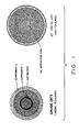
- a 10x10 cm silica gel coated glass plate was used. A drop of the crude oil or the fraction was dropped gently on the plate. The plate was allowed to stand at room temperature on a flat surface for from one minute to several hours. For light crude oils and fractions the separation was completed in a few minutes. For heavy crudes with very high viscosity such as SJV crude the separation required a few hours.
- FIG. 1 illustrates the TLC chromatogram of the asphaltene containing high fouling Crude (BT) showing distinctly the dark colored asphaltenes ring as a concentric ring in the chromatogram.
- BT high fouling Crude
- FIG. 1 illustrates the TLC chromatogram of an asphaltene-free distillate of Crude (BT).
- the chromatogram shows no presence of an asphaltene ring.
- This distillate of Crude (BT) shows no fouling tendency as measured by the Thermal Fouling Tester (TFT).
- TFT Thermal Fouling Tester
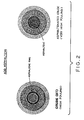
- a sample of the high fouling crude oil, Crude (BT) was modified by the addition of about 5 weight percent of asphaltenes (derived from Crude [BT]) to provide the asphaltenated Crude modification referenced in the description of Figure 2.
- the asphaltenated crude modification was subjected to chromatographic separation for one minute.
- the left diagrammatic view of Figure 2 is the same as illustrated in Figure 1.
- the right diagrammatic view of Figure 2 illustrates the increased area and intensity of the asphaltene ring resulting from a TLC chromatogram when asphaltenes are added to Crude (BT) to increase its fouling tendency. Note that the resulting ring appears as a disk.
- the Thermal Fouling Test was used to determine the fouling characteristics of 3 crude oils, a crude distillate by distillation, asphaltenated crude oil (BT) and deasphaltenated crude oil (BT).
- the Thermal Fouling Tester results presented in the above table gives the fouling characteristics of the various hydrocarbon streams.
- the data of Table II is seen to confirm the fouling tendencies or lack thereof of various hydrocarbon streams as predicted by the method of this invention.
- the left chromatogram of Figure 1 predicted the heavy fouling property of Crude (BT) as shown by Example 5.
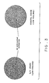
- Similar Examples 8 and 9 show the validity of the chromatograms of Figure 3 in predicting the low fouling tendencies of SJV and Coastal Crudes.
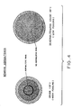
- Example 10 confirms the prediction from the right chromatogram of Figure 4 of the low fouling tendency of the Deasphaltenated Crude (BT).
Landscapes
- Chemical & Material Sciences (AREA)
- Health & Medical Sciences (AREA)
- Life Sciences & Earth Sciences (AREA)
- Biochemistry (AREA)
- Engineering & Computer Science (AREA)
- Pathology (AREA)
- Immunology (AREA)
- General Physics & Mathematics (AREA)
- General Health & Medical Sciences (AREA)
- Physics & Mathematics (AREA)
- Analytical Chemistry (AREA)
- Oil, Petroleum & Natural Gas (AREA)
- Medicinal Chemistry (AREA)
- Food Science & Technology (AREA)
- General Chemical & Material Sciences (AREA)
- Chemical Kinetics & Catalysis (AREA)
- Production Of Liquid Hydrocarbon Mixture For Refining Petroleum (AREA)
- Treatment Of Liquids With Adsorbents In General (AREA)
Claims (7)
Priority Applications (1)
| Application Number | Priority Date | Filing Date | Title |
|---|---|---|---|
| DE8686302800T DE3673517D1 (de) | 1986-04-15 | 1986-04-15 | Chromatographisches verfahren zur feststellung der verschmutzungsfaehigkeit von fluessigen kohlenwasserstoffverbindungen. |
Applications Claiming Priority (1)
| Application Number | Priority Date | Filing Date | Title |
|---|---|---|---|
| US06/723,598 US4751187A (en) | 1985-04-15 | 1985-04-15 | Chromatographic method for determining fouling tendency of liquid hydrocarbons |
Publications (3)
| Publication Number | Publication Date |
|---|---|
| EP0241607A2 EP0241607A2 (de) | 1987-10-21 |
| EP0241607A3 EP0241607A3 (en) | 1988-08-03 |
| EP0241607B1 true EP0241607B1 (de) | 1990-08-16 |
Family
ID=24906920
Family Applications (1)
| Application Number | Title | Priority Date | Filing Date |
|---|---|---|---|
| EP86302800A Expired - Lifetime EP0241607B1 (de) | 1985-04-15 | 1986-04-15 | Chromatographisches Verfahren zur Feststellung der Verschmutzungsfähigkeit von flüssigen Kohlenwasserstoffverbindungen |
Country Status (3)
| Country | Link |
|---|---|
| US (1) | US4751187A (de) |
| EP (1) | EP0241607B1 (de) |
| JP (1) | JP2784762B2 (de) |
Families Citing this family (10)
| Publication number | Priority date | Publication date | Assignee | Title |
|---|---|---|---|---|
| US5132225A (en) * | 1985-04-15 | 1992-07-21 | Exxon Chemical Patents Inc. | Method for continual monitoring and treating a hydrocarbon oil stream |
| US4751187A (en) * | 1985-04-15 | 1988-06-14 | Exxon Chemical Patents Inc. | Chromatographic method for determining fouling tendency of liquid hydrocarbons |
| US5066598A (en) * | 1986-06-20 | 1991-11-19 | Exxon Chemical Patents, Inc. | Method of characterizing the effectiveness of baseoil additives |
| US4853337A (en) * | 1987-05-11 | 1989-08-01 | Exxon Chemicals Patents Inc. | Blending of hydrocarbon liquids |
| US4964974A (en) * | 1988-11-10 | 1990-10-23 | Texaco Inc. | Microscopic examination of ebullated bed process effluent to control sediment |
| US4931164A (en) * | 1988-11-14 | 1990-06-05 | Exxon Chemical Patents Inc. | Antifoulant additive for light end hydrocarbons |
| US5313824A (en) * | 1992-09-30 | 1994-05-24 | Herguth Laboratories | Lubricating oil analysis method and kit |
| US5858213A (en) * | 1996-07-30 | 1999-01-12 | Exxon Research And Engineering Company | Monitoring for coke formation during hydrocarbon feed processing |
| US20100163461A1 (en) * | 2008-10-09 | 2010-07-01 | Wright Chris A | Method and system for controlling the amount of anti-fouling additive for particulate-induced fouling mitigation in refining operations |
| JP5790853B1 (ja) * | 2014-08-13 | 2015-10-07 | 栗田工業株式会社 | 石油組成物の成分分析方法及び成分分析装置 |
Citations (2)
| Publication number | Priority date | Publication date | Assignee | Title |
|---|---|---|---|---|
| US4751187A (en) * | 1985-04-15 | 1988-06-14 | Exxon Chemical Patents Inc. | Chromatographic method for determining fouling tendency of liquid hydrocarbons |
| US4752587A (en) * | 1985-04-15 | 1988-06-21 | Exxon Chemical Patents Inc. | Chromatographic method for determining fouling tendency of liquid hydrocarbons |
Family Cites Families (8)
| Publication number | Priority date | Publication date | Assignee | Title |
|---|---|---|---|---|
| US1756981A (en) * | 1925-01-24 | 1930-05-06 | Simplex Refining Company | Method of eliminating colloidal asphaltenes and carbenes from fuel oil |
| US2196989A (en) * | 1938-07-11 | 1940-04-16 | Phillips Petroleum Co | Process for treating hydrocarbons |
| US2927078A (en) * | 1957-01-29 | 1960-03-01 | Texaco Inc | Prevention of paraffin deposition |
| US2981684A (en) * | 1958-07-15 | 1961-04-25 | Continental Oil Co | Method of paraffin deposition control |
| US3049964A (en) * | 1959-08-10 | 1962-08-21 | Phillips Petroleum Co | Optical oil change indicator |
| SU455272A1 (ru) * | 1971-04-26 | 1974-12-30 | Северный научно-исследовательский институт промышленности | Устройство дл определени качества масла |
| US3776835A (en) * | 1972-02-23 | 1973-12-04 | Union Oil Co | Fouling rate reduction in hydrocarbon streams |
| US4440625A (en) * | 1981-09-24 | 1984-04-03 | Atlantic Richfield Co. | Method for minimizing fouling of heat exchanges |
-
1985
- 1985-04-15 US US06/723,598 patent/US4751187A/en not_active Expired - Lifetime
-
1986
- 1986-04-15 EP EP86302800A patent/EP0241607B1/de not_active Expired - Lifetime
-
1987
- 1987-07-20 JP JP62179267A patent/JP2784762B2/ja not_active Expired - Fee Related
Patent Citations (2)
| Publication number | Priority date | Publication date | Assignee | Title |
|---|---|---|---|---|
| US4751187A (en) * | 1985-04-15 | 1988-06-14 | Exxon Chemical Patents Inc. | Chromatographic method for determining fouling tendency of liquid hydrocarbons |
| US4752587A (en) * | 1985-04-15 | 1988-06-21 | Exxon Chemical Patents Inc. | Chromatographic method for determining fouling tendency of liquid hydrocarbons |
Also Published As
| Publication number | Publication date |
|---|---|
| JP2784762B2 (ja) | 1998-08-06 |
| EP0241607A3 (en) | 1988-08-03 |
| EP0241607A2 (de) | 1987-10-21 |
| US4751187A (en) | 1988-06-14 |
| JPS6435364A (en) | 1989-02-06 |
Similar Documents
| Publication | Publication Date | Title |
|---|---|---|
| Fan et al. | Evaluating crude oils by SARA analysis | |
| US5132225A (en) | Method for continual monitoring and treating a hydrocarbon oil stream | |
| US4671103A (en) | Method for determining crude oil fouling by high performance liquid chromatography | |
| Suatoni et al. | Rapid hydrocarbon group-type analysis by high performance liquid chromatography | |
| EP0241607B1 (de) | Chromatographisches Verfahren zur Feststellung der Verschmutzungsfähigkeit von flüssigen Kohlenwasserstoffverbindungen | |
| US4752587A (en) | Chromatographic method for determining fouling tendency of liquid hydrocarbons | |
| EP0241233B1 (de) | Verfahren zur Bestimmung der Beschmutzungs-Tendenz von Kohlenwasserstoffen | |
| US4853337A (en) | Blending of hydrocarbon liquids | |
| Alfredson | High-performance liquid chromatographic column switching techniques for rapid hydrocarbon group-type separations | |
| Ali et al. | Application of high performance liquid chromatography for hydrocarbon group type analysis of crude oils | |
| Kleinschmidt | Chromatographic method for the fractionation of asphalt into distinctive groups of components | |
| Robbins | Quantitative measurement of mass and aromaticity distributions for heavy distillates 1. Capabilities of the HPLC-2 system | |
| Dark | Crude oil hydrocarbon group separation quantitation | |
| Hostettler et al. | Use of geochemical biomarkers in bottom sediment to track oil from a spill, San Francisco Bay, California | |
| US4781892A (en) | Apparatus and method for determining fouling tendency of liquid hydrocarbons | |
| US4781893A (en) | Apparatus for determining fouling tendency of liquid hydrocarbons using polar polymeric membranes | |
| US4851355A (en) | Hydrocarbon group-type analyzer system | |
| JPH05223799A (ja) | 組成物中の飽和化合物、オレフィン及び芳香族炭化水素成分の定量分析法 | |
| Squicciarini | Paraffin, olefin, naphthene, and aromatic determination of gasoline and JP-4 jet fuel with supercritical fluid chromatography | |
| JPH0813971B2 (ja) | 炭化水素の着き垢傾向を決定する方法 | |
| Barman | Determination of hydrocarbon types in gasoline range samples by multidimensional gas chromatography, fluorescent indicator adsorption and bromine number methods | |
| YAMAMOTO | Analysis of Heavy Oils by FID-TLC (Part 4) A Rapid Method for Hydrocarbon Type Analysis of Heavy Oils | |
| Clerc et al. | Chromatographic Analysis of Gas Oils for Hydrocarbon Types | |
| Hanke | An experimental study in the nature of the film forming characteristics of crude oil fractions on steel surfaces and their influence on paraffin deposition | |
| Distillation | SIMULATED DISTILLATION |
Legal Events
| Date | Code | Title | Description |
|---|---|---|---|
| PUAI | Public reference made under article 153(3) epc to a published international application that has entered the european phase |
Free format text: ORIGINAL CODE: 0009012 |
|
| 17P | Request for examination filed |
Effective date: 19860502 |
|
| AK | Designated contracting states |
Kind code of ref document: A2 Designated state(s): BE DE FR GB IT NL |
|
| PUAL | Search report despatched |
Free format text: ORIGINAL CODE: 0009013 |
|
| AK | Designated contracting states |
Kind code of ref document: A3 Designated state(s): BE DE FR GB IT NL |
|
| 17Q | First examination report despatched |
Effective date: 19881025 |
|
| GRAA | (expected) grant |
Free format text: ORIGINAL CODE: 0009210 |
|
| AK | Designated contracting states |
Kind code of ref document: B1 Designated state(s): BE DE FR GB IT NL |
|
| ITF | It: translation for a ep patent filed | ||
| REF | Corresponds to: |
Ref document number: 3673517 Country of ref document: DE Date of ref document: 19900920 |
|
| ET | Fr: translation filed | ||
| ITTA | It: last paid annual fee | ||
| PLBE | No opposition filed within time limit |
Free format text: ORIGINAL CODE: 0009261 |
|
| STAA | Information on the status of an ep patent application or granted ep patent |
Free format text: STATUS: NO OPPOSITION FILED WITHIN TIME LIMIT |
|
| 26N | No opposition filed | ||
| REG | Reference to a national code |
Ref country code: GB Ref legal event code: IF02 |
|
| PGFP | Annual fee paid to national office [announced via postgrant information from national office to epo] |
Ref country code: NL Payment date: 20040316 Year of fee payment: 19 |
|
| PGFP | Annual fee paid to national office [announced via postgrant information from national office to epo] |
Ref country code: GB Payment date: 20040407 Year of fee payment: 19 |
|
| PGFP | Annual fee paid to national office [announced via postgrant information from national office to epo] |
Ref country code: FR Payment date: 20040420 Year of fee payment: 19 |
|
| PGFP | Annual fee paid to national office [announced via postgrant information from national office to epo] |
Ref country code: BE Payment date: 20040528 Year of fee payment: 19 |
|
| PGFP | Annual fee paid to national office [announced via postgrant information from national office to epo] |
Ref country code: DE Payment date: 20040601 Year of fee payment: 19 |
|
| PG25 | Lapsed in a contracting state [announced via postgrant information from national office to epo] |
Ref country code: IT Free format text: LAPSE BECAUSE OF NON-PAYMENT OF DUE FEES;WARNING: LAPSES OF ITALIAN PATENTS WITH EFFECTIVE DATE BEFORE 2007 MAY HAVE OCCURRED AT ANY TIME BEFORE 2007. THE CORRECT EFFECTIVE DATE MAY BE DIFFERENT FROM THE ONE RECORDED. Effective date: 20050415 Ref country code: GB Free format text: LAPSE BECAUSE OF NON-PAYMENT OF DUE FEES Effective date: 20050415 |
|
| PG25 | Lapsed in a contracting state [announced via postgrant information from national office to epo] |
Ref country code: BE Free format text: LAPSE BECAUSE OF NON-PAYMENT OF DUE FEES Effective date: 20050430 |
|
| BERE | Be: lapsed |
Owner name: *EXXON CHEMICAL PATENTS INC. Effective date: 20050430 |
|
| PG25 | Lapsed in a contracting state [announced via postgrant information from national office to epo] |
Ref country code: NL Free format text: LAPSE BECAUSE OF NON-PAYMENT OF DUE FEES Effective date: 20051101 Ref country code: DE Free format text: LAPSE BECAUSE OF NON-PAYMENT OF DUE FEES Effective date: 20051101 |
|
| GBPC | Gb: european patent ceased through non-payment of renewal fee |
Effective date: 20050415 |
|
| PG25 | Lapsed in a contracting state [announced via postgrant information from national office to epo] |
Ref country code: FR Free format text: LAPSE BECAUSE OF NON-PAYMENT OF DUE FEES Effective date: 20051230 |
|
| NLV4 | Nl: lapsed or anulled due to non-payment of the annual fee |
Effective date: 20051101 |
|
| REG | Reference to a national code |
Ref country code: FR Ref legal event code: ST Effective date: 20051230 |
|
| BERE | Be: lapsed |
Owner name: *EXXON CHEMICAL PATENTS INC. Effective date: 20050430 |