EP0241470B1 - Anordnung für ein lager - Google Patents
Anordnung für ein lager Download PDFInfo
- Publication number
- EP0241470B1 EP0241470B1 EP86900871A EP86900871A EP0241470B1 EP 0241470 B1 EP0241470 B1 EP 0241470B1 EP 86900871 A EP86900871 A EP 86900871A EP 86900871 A EP86900871 A EP 86900871A EP 0241470 B1 EP0241470 B1 EP 0241470B1
- Authority
- EP
- European Patent Office
- Prior art keywords
- bearing
- supporting
- bearing means
- supporting bodies
- means according
- Prior art date
- Legal status (The legal status is an assumption and is not a legal conclusion. Google has not performed a legal analysis and makes no representation as to the accuracy of the status listed.)
- Expired
Links
- 238000004519 manufacturing process Methods 0.000 description 3
- 239000002131 composite material Substances 0.000 description 1
- 230000007423 decrease Effects 0.000 description 1
- 238000010586 diagram Methods 0.000 description 1
- 230000001771 impaired effect Effects 0.000 description 1
- 238000009434 installation Methods 0.000 description 1
- 239000002184 metal Substances 0.000 description 1
- 230000002093 peripheral effect Effects 0.000 description 1
- 150000003839 salts Chemical class 0.000 description 1
- XLYOFNOQVPJJNP-UHFFFAOYSA-N water Substances O XLYOFNOQVPJJNP-UHFFFAOYSA-N 0.000 description 1
Images


Classifications
-
- F—MECHANICAL ENGINEERING; LIGHTING; HEATING; WEAPONS; BLASTING
- F16—ENGINEERING ELEMENTS AND UNITS; GENERAL MEASURES FOR PRODUCING AND MAINTAINING EFFECTIVE FUNCTIONING OF MACHINES OR INSTALLATIONS; THERMAL INSULATION IN GENERAL
- F16C—SHAFTS; FLEXIBLE SHAFTS; ELEMENTS OR CRANKSHAFT MECHANISMS; ROTARY BODIES OTHER THAN GEARING ELEMENTS; BEARINGS
- F16C41/00—Other accessories, e.g. devices integrated in the bearing not relating to the bearing function as such
- F16C41/02—Arrangements for equalising the load on a plurality of bearings or their elements
-
- B—PERFORMING OPERATIONS; TRANSPORTING
- B63—SHIPS OR OTHER WATERBORNE VESSELS; RELATED EQUIPMENT
- B63H—MARINE PROPULSION OR STEERING
- B63H9/00—Marine propulsion provided directly by wind power
- B63H9/04—Marine propulsion provided directly by wind power using sails or like wind-catching surfaces
- B63H9/08—Connections of sails to masts, spars, or the like
- B63H9/10—Running rigging, e.g. reefing equipment
- B63H9/1021—Reefing
- B63H9/1028—Reefing by furling around stays
-
- F—MECHANICAL ENGINEERING; LIGHTING; HEATING; WEAPONS; BLASTING
- F16—ENGINEERING ELEMENTS AND UNITS; GENERAL MEASURES FOR PRODUCING AND MAINTAINING EFFECTIVE FUNCTIONING OF MACHINES OR INSTALLATIONS; THERMAL INSULATION IN GENERAL
- F16C—SHAFTS; FLEXIBLE SHAFTS; ELEMENTS OR CRANKSHAFT MECHANISMS; ROTARY BODIES OTHER THAN GEARING ELEMENTS; BEARINGS
- F16C19/00—Bearings with rolling contact, for exclusively rotary movement
- F16C19/54—Systems consisting of a plurality of bearings with rolling friction
- F16C19/546—Systems with spaced apart rolling bearings including at least one angular contact bearing
- F16C19/547—Systems with spaced apart rolling bearings including at least one angular contact bearing with two angular contact rolling bearings
- F16C19/548—Systems with spaced apart rolling bearings including at least one angular contact bearing with two angular contact rolling bearings in O-arrangement
-
- F—MECHANICAL ENGINEERING; LIGHTING; HEATING; WEAPONS; BLASTING
- F16—ENGINEERING ELEMENTS AND UNITS; GENERAL MEASURES FOR PRODUCING AND MAINTAINING EFFECTIVE FUNCTIONING OF MACHINES OR INSTALLATIONS; THERMAL INSULATION IN GENERAL
- F16C—SHAFTS; FLEXIBLE SHAFTS; ELEMENTS OR CRANKSHAFT MECHANISMS; ROTARY BODIES OTHER THAN GEARING ELEMENTS; BEARINGS
- F16C19/00—Bearings with rolling contact, for exclusively rotary movement
- F16C19/02—Bearings with rolling contact, for exclusively rotary movement with bearing balls essentially of the same size in one or more circular rows
- F16C19/14—Bearings with rolling contact, for exclusively rotary movement with bearing balls essentially of the same size in one or more circular rows for both radial and axial load
- F16C19/16—Bearings with rolling contact, for exclusively rotary movement with bearing balls essentially of the same size in one or more circular rows for both radial and axial load with a single row of balls
- F16C19/163—Bearings with rolling contact, for exclusively rotary movement with bearing balls essentially of the same size in one or more circular rows for both radial and axial load with a single row of balls with angular contact
-
- F—MECHANICAL ENGINEERING; LIGHTING; HEATING; WEAPONS; BLASTING
- F16—ENGINEERING ELEMENTS AND UNITS; GENERAL MEASURES FOR PRODUCING AND MAINTAINING EFFECTIVE FUNCTIONING OF MACHINES OR INSTALLATIONS; THERMAL INSULATION IN GENERAL
- F16C—SHAFTS; FLEXIBLE SHAFTS; ELEMENTS OR CRANKSHAFT MECHANISMS; ROTARY BODIES OTHER THAN GEARING ELEMENTS; BEARINGS
- F16C2326/00—Articles relating to transporting
- F16C2326/30—Ships, e.g. propelling shafts and bearings therefor
Definitions
- the present invention relates to a bearing means according to the preamble of claim 1.
- the bearing means disclosed in German Patent 1 708 557 comprises a moving upper part and a fixed lower part with a ring attached to each of the components, between which balls contained in the bearing are arranged to run.
- the principal object of the present invention is essentially to propose a bearing means of the kind described above which will overcome said problems of achieving the best possible load distribution, and without the need for bearing play, by distributing the load acting upon the bearing in the most advantageous fashion, thereby producing a considerable increase in the strength of the bearing, but without as a consequence having t Q increase the dimensions of the bearing to a corresponding degree.
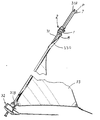
- the bearing means may, for example, be applied to a so-called swivel which is used on board of a boat for a foresail so arranged as to run along a foremast.
- the bearing means in accordance with the present invention as defined in claim 1 differs significantly from the previously disclosed means referred to above.
- the bearing means comprises a bearing body receiving a force and being situated between two bearing rings or other appropriate bearing components, each having its own bearings.
- a number of axially extending supporting bodies are accommodated between the bearing body and each bearing ring. These supporting bodies are so distributed that two supporting bodies or the free ends of a common supporting body are situated between the center of the bearing and the outside of the bearing to either side of the center of the bearing viewed in a direction from one bearing ring to the other bearing ring.
- bearing rings and the bearing body do not call for a high degree of manufacturing accuracy and do not require to be elastic, although bearing play is permissible in the bearing without its function being impaired significantly in the event of dirt or salt water, etc., finding its way inside.
- the component parts are also rigid, which permits the simple manufacture of the bearing arrangement, but which also means that its function will be entirely as specified in spite of what is stated above.
- the invention is applicable to a large number of different bearing means in which load instances can arise with moments which act outside a bearing in question, although the invention is described in the following with reference to the drawings, which illustrate a bearing means for a so-called lowering swivel, for the sake of simplicity only in conjunction with a swivel bearing.
- a bearing means 1 for a swivel 2, which is illustrated in the drawings, is arranged to be capable of being acted upon by an axial active force P which is applied at a point radially displaced outside the bearing means.
- the bearing means comprises two sleeve-shaped bearing bodies 3 and 4 capable of being rotated in relation to one another and which are provided with eyes 5 and 6 or other appropriate attachment components to which, for instance, a hoisting cable 7 or a sail attachment device 8 on board of a floating vessel can be attached in such a way as to be capable of being released.
- the two bearing bodies 3, 4 are preferably so arranged as to be accommodated by and connected to a bearing tube 9 acting as a central sleeve, said tube being capable of being connected to an intermediate connecting element 10 at each of ends 9A, 9B of a hollow inner space 11 of the sleeve.
- a flange 12 on the bearing tube 9 is so arranged as to constitute with a section 13 a bearing surface for a first bearing 14, such as a ball bearing, a roller bearing or a sliding bearing, acting between the first bearing body 3 and the bearing tube 9.
- a second bearing 15 is so arranged as to act between the two bearing bodies 3, 4.
- An intermediate bearing ring 16 or 17 is so arranged as to act between the flange section 13 and the first bearing 14, or between the first bearing body 3 and the second bearing 15, which is in contact with a flange section 19 of a flange 20 on the other bearing body 4, whilst inner and outer ball bearing rings 21, 22 and 23, 24 are so arranged as to act between ball bearings 25 and 26 in the bearings 14 and 15.
- the respective bearing rings 16, 17 have for this purpose an accommodating section 16A, 17A which fits the associated ball bearing ring 23, 24.
- the installation of the swivel 2 is made, after the intermediate connecting element 10 has been accommodated in the inner space 11 of the bearing tube 9 and has been screwed or fastened in other manner securely to the bearing tube 9, by sliding the bearing bodies 3, 4 with their associated bearing components 21, 25, 23, 16 and 17, 24, 26, 22 onto a rod-shaped part 27 of the bearing tube 9 and by rotating the bearing body 4 in relation to the bearing tube 9.
- an attachment device 28 on the bearing tube 9 will interact with a matching attachment element 29 on the bearing body 4, whereupon the bearing tube 9 and the bearing body 4 are locked together by means of, for example, a screw in order to prevent rotating movement in relation to one another.
- An annular thicker section 30 of the bearing tube 9 is so arranged as to interact with and to form a stop for the bearing body 4.
- the intermediate connecting element 10 which may be manufactured from a so-called composite material, has internally a recess which provides positive engagement with the peripheral form of a roller foresail arm 31, or is attached in some other appropriate manner in order to prevent rotation of the swivel 2 in relation to the roller foresail arm 31, which is attached in a previously disclosed fashion at its ends 31A, 31 B to the top of a mast or to a rotating device 32 so as to permit a sail 33 to be rolled or unrolled onto or from the arm 31, an upper end 33A of the sail, by its connection to the swivel 2 and after having been hoisted to the desired level, being held fast by means of the cable 7 which is capable of being connected to a hoisting device.
- the aim is to provide the bearing means 1 with the maximum load distribution.
- a number of supporting bodies 34 - 36 and 37 - 39 are provided for this purpose which are capable of acting between component parts of the bearing means 1 and are distributed around the circumference of the bearing means in such a way that the load, which acts upon the bearing 1, is displaced laterally in relation to a central axis 40 of the bearing means and is transferred to the bearing means 1 radially displaced inwards towards the central axis 40.
- the supporting bodies 34 - 39 preferably extend axially along the central axis 40 of the bearing. In the illustrated embodiment the three supporting bodies 34 - 36 and 37 - 39 are so arranged as to act on the respective bearing, 14 and 15.
- the supporting bodies 34 - 36 and 37 - 39 are distributed at a certain distance from one another and are so arranged as to act around the circumference of a supporting surface 41 and 42 on the first bearing body 3 so as to interact with matching bearing rings 16 and 17, which act between the supporting surface 41, 42 and the bearing 14, 15.
- the supporting bodies 34 - 39 may be integrated with the supporting surface 41, 42 in question, which may be essentially flat apart from said supporting bodies 34 - 39.
- Two supporting bodies 35, 36 and 38, 39 can be positioned between the central axis 40 and an outer part 1A of the bearing means on two supporting surfaces 41, 42 of an annular bearing body component 45 which face away from one another and are situated at a certain distance from one another along the bearing means 1.
- Said supporting bodies 35, 36 and 38, 39 which are arranged in pairs are so arranged in this way as to act upon one side 43 and 44 of the bearing body viewed in relation to the central axis 40, on each part 41A, 42A of the supporting surface 41, 42, in this way giving rise to a moment which counteracts that of the force applied to the attachment eye 5 outside the bearing means 1, the direction of which is indicated by the arrow 46.
- the supporting bodies 34 - 39 are preferably so arranged as to be accommodated in a matching annular groove 48 and 49 in the respective bearing rings 16 and 17, for instance by having a cross-sectional form which matches the cross-sectional form of the bearing ring groove 48, 49. If the bearing means 1 is subjected to radial loading, then there will be advantages to be gained from arranging the grooves 48, 49 so as to have an essentially "U"-shaped cross-sectional profile, in order to prevent unfavourable bearing conditions from arising.
- the supporting bodies 34 - 39 can also be displaced in a radial direction towards the inside of said supporting surface 41, 42.
- a further conceivable bearing alternative involves the arrangement of a single supporting body in each bearing supporting surface 41, 42.
- the form of said supporting bodies in this case is preferably a part of a circle greater than 180°.
- These supporting bodies are turned so as to overlap one another, viewed in the longitudinal direction of the bearing means along its central axis, so that the free ends of each supporting body are situated between the central axis 40 of the bearing means and its bearing side 43 or 44 concerned, for example in the area of the supporting bodies 35, 36 and 38, 39 illustrated in Fig. 3.
- the groove in the bearing rings 16, 17 may have a cross-sectional form having at least one cylindrical lateral surface and a flat bottom for the purpose, among other things, of reducing the incidence of axial forces attributable to the fact that the rings 16, 17 are displaced in relation to one another.
- the bearings may be so arranged as to act directly upon the bearing bodies 3, 4, 9 concerned or upon some other appropriate bearing component.
Landscapes
- Engineering & Computer Science (AREA)
- General Engineering & Computer Science (AREA)
- Mechanical Engineering (AREA)
- Life Sciences & Earth Sciences (AREA)
- Sustainable Development (AREA)
- Sustainable Energy (AREA)
- Chemical & Material Sciences (AREA)
- Combustion & Propulsion (AREA)
- Ocean & Marine Engineering (AREA)
- Rolling Contact Bearings (AREA)
- Support Of The Bearing (AREA)
- Shafts, Cranks, Connecting Bars, And Related Bearings (AREA)
Claims (9)
Priority Applications (1)
| Application Number | Priority Date | Filing Date | Title |
|---|---|---|---|
| AT86900871T ATE46944T1 (de) | 1985-01-10 | 1986-01-10 | Anordnung fuer ein lager. |
Applications Claiming Priority (2)
| Application Number | Priority Date | Filing Date | Title |
|---|---|---|---|
| SE8500103 | 1985-01-10 | ||
| SE8500103A SE446213B (sv) | 1985-01-10 | 1985-01-10 | Anordning vid en lagring som paverkas av en axiell last anbringad radiellt forskjutet utanfor lagringen |
Publications (2)
| Publication Number | Publication Date |
|---|---|
| EP0241470A1 EP0241470A1 (de) | 1987-10-21 |
| EP0241470B1 true EP0241470B1 (de) | 1989-10-04 |
Family
ID=20358721
Family Applications (1)
| Application Number | Title | Priority Date | Filing Date |
|---|---|---|---|
| EP86900871A Expired EP0241470B1 (de) | 1985-01-10 | 1986-01-10 | Anordnung für ein lager |
Country Status (6)
| Country | Link |
|---|---|
| US (1) | US4750879A (de) |
| EP (1) | EP0241470B1 (de) |
| AU (1) | AU588277B2 (de) |
| DE (1) | DE3666079D1 (de) |
| SE (1) | SE446213B (de) |
| WO (1) | WO1986004123A1 (de) |
Families Citing this family (4)
| Publication number | Priority date | Publication date | Assignee | Title |
|---|---|---|---|---|
| EP1181746A4 (de) * | 1999-05-12 | 2007-05-02 | K & K Stamping Company | Elektrischer verbinder und sein herstellungsverfahren |
| US6318285B1 (en) * | 2000-09-19 | 2001-11-20 | Harken, Inc. | Furling sail system |
| ITMI20010148U1 (it) * | 2001-03-15 | 2002-09-16 | Greghi Renzo | Dispositivo di avvolgimento per vele |
| US6796257B1 (en) * | 2002-01-18 | 2004-09-28 | Solution Inc. | Zero moment furling swivel |
Family Cites Families (7)
| Publication number | Priority date | Publication date | Assignee | Title |
|---|---|---|---|---|
| US933974A (en) * | 1908-07-30 | 1909-09-14 | Deutsche Waffen & Munitionsfab | Foot-step ball-bearing. |
| US1176889A (en) * | 1913-09-30 | 1916-03-28 | Max Gohlke | Thrust-bearing. |
| US1734223A (en) * | 1926-12-20 | 1929-11-05 | John M Melott | Balanced thrust bearing |
| US1914204A (en) * | 1931-08-17 | 1933-06-13 | Bassick Co | Swivel bearing |
| DE1708557A1 (de) * | 1968-02-21 | 1972-03-02 | Erwin Bargmann | Einrillige,zur Aufnahme von Kippkraeften bestimmte Kugeldrehverbindung fuer Bagger und Krane |
| US3650583A (en) * | 1970-11-18 | 1972-03-21 | Artur Markovich Itin | Antifriction thrust bearing of a rotary table |
| US4248281A (en) * | 1979-06-18 | 1981-02-03 | Hood Enterprises, Inc. | Roll-reefing jib sail |
-
1985
- 1985-01-10 SE SE8500103A patent/SE446213B/sv not_active IP Right Cessation
-
1986
- 1986-01-10 AU AU53137/86A patent/AU588277B2/en not_active Ceased
- 1986-01-10 EP EP86900871A patent/EP0241470B1/de not_active Expired
- 1986-01-10 DE DE8686900871T patent/DE3666079D1/de not_active Expired
- 1986-01-10 WO PCT/SE1986/000007 patent/WO1986004123A1/en not_active Ceased
- 1986-01-10 US US06/908,018 patent/US4750879A/en not_active Expired - Lifetime
Also Published As
| Publication number | Publication date |
|---|---|
| EP0241470A1 (de) | 1987-10-21 |
| US4750879A (en) | 1988-06-14 |
| SE8500103D0 (sv) | 1985-01-10 |
| WO1986004123A1 (en) | 1986-07-17 |
| AU5313786A (en) | 1986-07-29 |
| SE446213B (sv) | 1986-08-18 |
| DE3666079D1 (en) | 1989-11-09 |
| AU588277B2 (en) | 1989-09-14 |
| SE8500103L (sv) | 1986-07-11 |
Similar Documents
| Publication | Publication Date | Title |
|---|---|---|
| US4981373A (en) | Fixing structure for thrust roller bearing | |
| US4955310A (en) | Bearing arrangement for single point terminal | |
| KR920010895B1 (ko) | 대형 중공구름 베어링 | |
| EP1001899B1 (de) | Vorgespannte lageranordnung für die halterung eines flugzeugpropellerblatts | |
| US4705490A (en) | Hooke's-type joint for a universal shaft | |
| EP0906216B1 (de) | Auflagerstruktur für einen verankerungsdrehturm und einbauverfahren hierfür | |
| US4909641A (en) | Bearing with expanded load zone | |
| GB1580269A (en) | Double row rolling bearing | |
| EP0241470B1 (de) | Anordnung für ein lager | |
| KR20200018333A (ko) | 배럴 및 당해 배럴을 구비한 휠 | |
| US20220010839A1 (en) | Large rolling bearing | |
| US4881830A (en) | Split ring roller bearing cage | |
| US5567057A (en) | Tilting pad thrust bearing assembly | |
| JPS62118115A (ja) | ころがり軸受の支持体 | |
| KR20000005022A (ko) | 레이디얼 롤링 베어링 | |
| US5123756A (en) | Roller bearing and segmented roller retainer therefor | |
| US4923313A (en) | Device in rolling bearings | |
| JP3584040B2 (ja) | ころに正のスキュー角を与える手段を有するころ軸受 | |
| US20040141674A1 (en) | Method for forming a taper roller bearing assembly | |
| US4223961A (en) | Orientation ring with bearings | |
| CA2185482A1 (en) | Pump with improved bearing arrangement for axial position control | |
| US4196947A (en) | Adjustable four point contact bearing | |
| JPS6114747Y2 (de) | ||
| US5417502A (en) | Cage for full-type roller bearings | |
| GB2053380A (en) | Three-point ball bearing |
Legal Events
| Date | Code | Title | Description |
|---|---|---|---|
| PUAI | Public reference made under article 153(3) epc to a published international application that has entered the european phase |
Free format text: ORIGINAL CODE: 0009012 |
|
| 17P | Request for examination filed |
Effective date: 19870709 |
|
| AK | Designated contracting states |
Kind code of ref document: A1 Designated state(s): AT BE CH DE FR GB IT LI LU NL SE |
|
| 17Q | First examination report despatched |
Effective date: 19880706 |
|
| ITF | It: translation for a ep patent filed | ||
| GRAA | (expected) grant |
Free format text: ORIGINAL CODE: 0009210 |
|
| AK | Designated contracting states |
Kind code of ref document: B1 Designated state(s): AT BE CH DE FR GB IT LI LU NL SE |
|
| REF | Corresponds to: |
Ref document number: 46944 Country of ref document: AT Date of ref document: 19891015 Kind code of ref document: T |
|
| REF | Corresponds to: |
Ref document number: 3666079 Country of ref document: DE Date of ref document: 19891109 |
|
| ET | Fr: translation filed | ||
| PG25 | Lapsed in a contracting state [announced via postgrant information from national office to epo] |
Ref country code: SE Effective date: 19900101 |
|
| PLBE | No opposition filed within time limit |
Free format text: ORIGINAL CODE: 0009261 |
|
| STAA | Information on the status of an ep patent application or granted ep patent |
Free format text: STATUS: NO OPPOSITION FILED WITHIN TIME LIMIT |
|
| 26N | No opposition filed | ||
| EPTA | Lu: last paid annual fee | ||
| ITTA | It: last paid annual fee | ||
| PGFP | Annual fee paid to national office [announced via postgrant information from national office to epo] |
Ref country code: AT Payment date: 19980129 Year of fee payment: 13 |
|
| PGFP | Annual fee paid to national office [announced via postgrant information from national office to epo] |
Ref country code: CH Payment date: 19980130 Year of fee payment: 13 |
|
| PGFP | Annual fee paid to national office [announced via postgrant information from national office to epo] |
Ref country code: BE Payment date: 19980211 Year of fee payment: 13 |
|
| PGFP | Annual fee paid to national office [announced via postgrant information from national office to epo] |
Ref country code: LU Payment date: 19980217 Year of fee payment: 13 |
|
| PG25 | Lapsed in a contracting state [announced via postgrant information from national office to epo] |
Ref country code: LU Free format text: LAPSE BECAUSE OF NON-PAYMENT OF DUE FEES Effective date: 19990110 Ref country code: AT Free format text: LAPSE BECAUSE OF NON-PAYMENT OF DUE FEES Effective date: 19990110 |
|
| PGFP | Annual fee paid to national office [announced via postgrant information from national office to epo] |
Ref country code: NL Payment date: 19990129 Year of fee payment: 14 |
|
| PG25 | Lapsed in a contracting state [announced via postgrant information from national office to epo] |
Ref country code: LI Free format text: LAPSE BECAUSE OF NON-PAYMENT OF DUE FEES Effective date: 19990131 Ref country code: CH Free format text: LAPSE BECAUSE OF NON-PAYMENT OF DUE FEES Effective date: 19990131 Ref country code: BE Free format text: LAPSE BECAUSE OF NON-PAYMENT OF DUE FEES Effective date: 19990131 |
|
| BERE | Be: lapsed |
Owner name: JOHNSON LARS Effective date: 19990131 |
|
| REG | Reference to a national code |
Ref country code: CH Ref legal event code: PL |
|
| PG25 | Lapsed in a contracting state [announced via postgrant information from national office to epo] |
Ref country code: NL Free format text: LAPSE BECAUSE OF NON-PAYMENT OF DUE FEES Effective date: 20000801 |
|
| NLV4 | Nl: lapsed or anulled due to non-payment of the annual fee |
Effective date: 20000801 |
|
| PGFP | Annual fee paid to national office [announced via postgrant information from national office to epo] |
Ref country code: DE Payment date: 20010227 Year of fee payment: 16 |
|
| REG | Reference to a national code |
Ref country code: GB Ref legal event code: IF02 |
|
| PG25 | Lapsed in a contracting state [announced via postgrant information from national office to epo] |
Ref country code: DE Free format text: LAPSE BECAUSE OF NON-PAYMENT OF DUE FEES Effective date: 20020801 |
|
| PGFP | Annual fee paid to national office [announced via postgrant information from national office to epo] |
Ref country code: GB Payment date: 20030108 Year of fee payment: 18 |
|
| PGFP | Annual fee paid to national office [announced via postgrant information from national office to epo] |
Ref country code: FR Payment date: 20030127 Year of fee payment: 18 |
|
| PG25 | Lapsed in a contracting state [announced via postgrant information from national office to epo] |
Ref country code: GB Free format text: LAPSE BECAUSE OF NON-PAYMENT OF DUE FEES Effective date: 20040110 |
|
| GBPC | Gb: european patent ceased through non-payment of renewal fee |
Effective date: 20040110 |
|
| PG25 | Lapsed in a contracting state [announced via postgrant information from national office to epo] |
Ref country code: FR Free format text: LAPSE BECAUSE OF NON-PAYMENT OF DUE FEES Effective date: 20040930 |
|
| REG | Reference to a national code |
Ref country code: FR Ref legal event code: ST |
|
| PG25 | Lapsed in a contracting state [announced via postgrant information from national office to epo] |
Ref country code: IT Free format text: LAPSE BECAUSE OF NON-PAYMENT OF DUE FEES;WARNING: LAPSES OF ITALIAN PATENTS WITH EFFECTIVE DATE BEFORE 2007 MAY HAVE OCCURRED AT ANY TIME BEFORE 2007. THE CORRECT EFFECTIVE DATE MAY BE DIFFERENT FROM THE ONE RECORDED. Effective date: 20050110 |