EP0241373A1 - Stromversorgungsvorrichtung für den Glühfaden einer Röntgenröhre - Google Patents
Stromversorgungsvorrichtung für den Glühfaden einer Röntgenröhre Download PDFInfo
- Publication number
- EP0241373A1 EP0241373A1 EP87400774A EP87400774A EP0241373A1 EP 0241373 A1 EP0241373 A1 EP 0241373A1 EP 87400774 A EP87400774 A EP 87400774A EP 87400774 A EP87400774 A EP 87400774A EP 0241373 A1 EP0241373 A1 EP 0241373A1
- Authority
- EP
- European Patent Office
- Prior art keywords
- current
- filament
- circuit
- frequency
- supply device
- Prior art date
- Legal status (The legal status is an assumption and is not a legal conclusion. Google has not performed a legal analysis and makes no representation as to the accuracy of the status listed.)
- Granted
Links
- 238000010438 heat treatment Methods 0.000 claims abstract description 47
- 239000003990 capacitor Substances 0.000 claims description 20
- 238000004804 winding Methods 0.000 claims description 11
- 230000033228 biological regulation Effects 0.000 claims description 10
- 230000001105 regulatory effect Effects 0.000 claims description 6
- 230000005669 field effect Effects 0.000 claims description 3
- 238000002955 isolation Methods 0.000 description 7
- 238000009434 installation Methods 0.000 description 5
- 230000000903 blocking effect Effects 0.000 description 4
- 230000007423 decrease Effects 0.000 description 2
- 238000010292 electrical insulation Methods 0.000 description 2
- 230000004048 modification Effects 0.000 description 2
- 238000012986 modification Methods 0.000 description 2
- 238000003745 diagnosis Methods 0.000 description 1
- 230000009977 dual effect Effects 0.000 description 1
- 238000010894 electron beam technology Methods 0.000 description 1
- 230000002349 favourable effect Effects 0.000 description 1
- 238000005259 measurement Methods 0.000 description 1
- 238000000034 method Methods 0.000 description 1
- 210000000056 organ Anatomy 0.000 description 1
- 238000002601 radiography Methods 0.000 description 1
- 230000001869 rapid Effects 0.000 description 1
Images

Classifications
-
- H—ELECTRICITY
- H05—ELECTRIC TECHNIQUES NOT OTHERWISE PROVIDED FOR
- H05G—X-RAY TECHNIQUE
- H05G1/00—X-ray apparatus involving X-ray tubes; Circuits therefor
- H05G1/08—Electrical details
- H05G1/26—Measuring, controlling or protecting
- H05G1/30—Controlling
- H05G1/34—Anode current, heater current or heater voltage of X-ray tube
-
- H—ELECTRICITY
- H05—ELECTRIC TECHNIQUES NOT OTHERWISE PROVIDED FOR
- H05G—X-RAY TECHNIQUE
- H05G1/00—X-ray apparatus involving X-ray tubes; Circuits therefor
- H05G1/08—Electrical details
- H05G1/10—Power supply arrangements for feeding the X-ray tube
- H05G1/20—Power supply arrangements for feeding the X-ray tube with high-frequency AC; with pulse trains
Definitions
- the invention relates to a device for supplying current to a filament, in particular to an X-ray tube as used in radiodiagnostic installations.
- the invention is particularly applicable in cases where it is necessary to successively supply filaments of very different resistances, with high current dynamics.
- X-ray tubes for medical diagnosis are generally constituted as a diode, that is to say by two electrodes of which one called cathode emits electrons, and the other is called anode and receives these electrons on a small surface which is the source of X-rays.
- the cathode has a heated filament which is the source of electrons.
- a so-called anodic current is established in the circuit, through the generator, and crosses the space between the cathode and the anode in the form of an electron beam whose intensity depends on the temperature of the filament; this temperature being a function of the power dissipated in the filament, that is to say the current, called heating current, which circulates in the filament.
- the quantity of X-ray emitted by the anode depends mainly on the intensity of the anode current, and therefore on the intensity of the heating current of the filament.
- the filament heating current constitutes one of the important parameters which must be determined for each exposure of radiography or radioscopy, during a radiological examination of a patient.
- the parameters of the pose are determined according to the nature of the examination. Generally, these parameters are predetermined by an operator who displays the values on a console control, by which is controlled the operation of the various organs of a radiodiagnostic installation, such as for example, high voltage generator and generator of the filament heating current. It is also common in certain installations for the values of these parameters to be predetermined using a microprocessor device incorporated or not in the control console, and which calculates and programs the optimum values of these parameters, depending for example on the type of examination desired by the practitioner, and according to the specific characteristics of the installation.
- this operation consists in particular in programming different values, such as for example: duration of the exposure time, energy of the X-ray by the choice of the value of the high voltage applied between the anode and the cathode, and intensity of the anodic current by the choice in particular of a value of the intensity of the filament heating current.
- the intensity of the heating current can be modified significantly, from one pose to a next pose, for example from 1.5 amperes to 5.5 amperes.
- radiodiagnostic installations may comprise several X-ray tubes, having different characteristics, which are put into operation successively, sometimes during the same examination; these X-ray tubes may include filaments whose value of the ohmic resistance can vary considerably from one tube to another, from 0.6 Ohms to 4.5 Ohms for example.
- a heating current generator making it possible to quickly obtain, that is to say automatically, a value of the heating current included in the range of values previously mentioned, and this regardless of the value of the resistance of the supplied filament.
- the generator which produces the heating current must supply the latter in a very wide power range. It must also, in this power range, ensure sufficient quality to regulate the heating current, and allow the desired intensity value to be obtained quickly and automatically, as defined for example by a set value; this set value being able to vary from one pose to a next pose.
- the heating current generators according to the prior art do not make it possible to obtain these conditions satisfactorily: either they require manual adjustments as a function of the intensity of the heating current and of the resistance value of the filament; either they allow power dynamics to the detriment of the quality of regulation; or that the conditions of power dynamics, automation and regulatory qualities lead to the design of complex generators, that is to say fragile, unreliable, or bulky and bulky and of a high price.
- the regulation of the filament heating current is further complicated by the fact that the cathode, and the filament of the X-ray tube, are brought to the negative potential of high voltage; also, the problems of electrical insulation generally lead to applying to the filament the heating energy by means of an isolation transformer, the primary winding of which represents the load of the filament. Therefore the heating current is produced according to an alternating current whose measurement of the effective value can also present problems.
- the supply device according to the invention does not have the above-mentioned drawbacks, thanks to a new arrangement which makes it a device which is simple to produce and simple to implement.
- the present invention relates to a device for supplying current to a filament of an X-ray tube, making it possible to automatically obtain a heating current whose intensity corresponds to a set value, this intensity being included in the range of intensities which can be applied to a filament, and this for all the current ohmic resistance values of the filament.
- a device for supplying current to a filament of at least one X-ray tube comprising, a generator supplying control pulses, an inverter receiving the control pulses and producing a current in a load circuit of alternative heating from a direct voltage, a regulation circuit regulating the heating current as a function of a set value, the load circuit comprising a primary winding of a transformer through which the heating current is applied to the filament, the heating current having the same frequency as the frequency of the control pulses, is characterized in that it comprises an oscillating circuit arranged in the load circuit, and in that the regulation circuit delivers a signal of error applied to the generator to modify the frequency of the control pulses, so as to modify the impedance of the oscillating circuit until a value of the current of the heating corresponding to the set value.
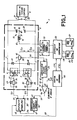
- Figure 1 shows a supply device 1 according to the invention allowing, in the non-limiting example described, to ali by running the filament of an X-ray tube, for example selected from several X-ray tubes, of which only two tubes 26, 27 are shown in the example described.
- the X-ray tubes are of a conventional type each comprising an anode, 28, 29 and a cathode 23, 24 represented by the filament which it contains.
- the tubes 26, 27 are supplied with high voltage by conventional means (not shown).
- the filament 23.24 of the tube 26.27 selected is brought to the negative potential - HT of the high voltage, and the problems of electrical insulation impose to apply to the filament 23.24 the electrical energy necessary for its heating. , via an isolation transformer 30.
- the selection of the first or second tube 26, 27 is made by connecting the corresponding filament 23, 24, to the secondary winding 31 of the transformer 30, by means of a switching device. 35, comprising switches (not shown) constituted for example by electromechanical relays; the transformer 30 comprising a primary winding 12 to which is applied a heating current I delivered by an inverter 2.
- the control of the switching device 35 can take place either by manual control, or automatically in the context of programmed sequences controlled for example by a control console 40; the latter being connected to the switching device 35 by a first and a second link CT1, CT2 by which it can select the first or the second tube 26,27, the first tube 26 for example, so as to apply to the filament 23 of this last a current I ⁇ for its heating.
- a tube 26, 27 can be carried out in a different way, such as for example by switching at the level of the primary of the isolation transformer.
- an isolation transformer in this case being associated with each filament.
- the supply device 1 also comprises a source of regulated DC voltage 3, delivering via terminals 27, 28 respectively the positive polarity + and the negative polarity - of a DC voltage V1, regulated, having for example a value of 200 Volts.
- the voltage source 3 is constituted in a conventional manner and develops the direct voltage V1 from, for example, a single-phase voltage (not shown) of 220 V.
- the inverter 2 is supplied by the DC voltage V1, from which it produces an AC voltage.
- the inverter 2 comprises two electronic switching means 4,5 arranged in series between the positive pole + and the negative pole - of the DC voltage V1.
- the two switching means 4,5 are constituted by field effect transistors.
- the source S of the first transistor 4 is connected to the positive pole + of the DC voltage V1 and its drain D is connected to the source S of the second transistor 5, whose drain D is connected to the negative pole - of the DC voltage V1.
- a first and a second diode d1, d2 are respectively connected in parallel on the first and the second transistor 4,5; the first diode d1 having its cathode connected to the + pole of the voltage V1 and its anode connected on the one hand, to the junction 6 between the drain of the first transistor 4 and the source of the second transitor 5, and connected on the other hand to the cathode of the second diode d2, the anode of which is connected to the negative pole - of the DC voltage V1.
- the junction 6 is also connected to the first end 7 of a current sensor means 9, the second end 10 of which is connected to the first end 11 of the primary winding 12 of the isolation transformer 30.
- the second end 14 of the primary winding 12 is connected to the first end 15 of an inductor 16 whose second end 17 is connected to a capacitive midpoint 18.
- the capacitive midpoint 18 is formed by the junction of a first and a second capacitor 19.20 connected in series between the positive and negative terminals +, - of the DC voltage V1; the first capacitor 19 being connected to the positive pole +, and the second capacitor 20 being connected to the negative pole -.
- the two capacitors 19 and 20 form a capacitor which is placed in series with the inductor 16, to form an oscillating circuit 13 arranged in series with the primary winding 12 of the transformer 13, with which it constitutes a charging circuit 12-13 .
- the primary winding 12 represents the filament 23 whose ohmic resistance R is reported in the charging circuit 12-13.
- the filament 23 is of a conventional type, its resistance R can have any value included in the current value range, for example between 0.6 Ohms and 4.5 Ohms.
- the current I ⁇ in the secondary circuit of the transformer 30, where the filament 23 is disposed being proportional to the current I flowing in the circuit of the primary winding or load circuit 12-13, according to a known ratio, and the resistance R of the filament 23 being reported in the charging circuit 12-13, it is the current I which flows in the charging circuit 12-13 which is called heating current for the sake of clarity of the description.
- the current sensor 9 is placed in the charging circuit 12-13 and delivers by an output 59 a signal S1 proportional to the pseudo-sinusoidal heating current I; the current sensor 9 is of a conventional type, such as for example constituted by an intensity transformer.
- the signal S1 proportional to the heating current I, is applied to the input 61 of a converter device 25, which conventionally processes the values of the signal S1, to provide by an output 62, a second signal S2 corresponding to the effective value of the heating current I.
- These effective values are used to regulate the current I in the primary circuit or load circuit 12-13 which allows, thanks in particular to the isolation transformer 30 with low leakage, to carry out a control rigorous current I ⁇ passing through the filament 23 ensuring better proportionality between the current I 'in the filament 23 and the current I in the charging circuit 12-13.
- the second signal S2 is applied to the first input 41 of an error processor 42, constituted for example by a differential amplifier.
- the second input 43 of the error processor 42 receives a setpoint value VC corresponding to the desired value of the heating current I; this setpoint being for example delivered by the control console 40 which, for this purpose, is connected by a link 63 to the second input 43 of the error processor 42.
- the error processor 42 delivers to its output 44 an error signal SE proportional to the difference between the second signal S2 and the set value VC.
- the error signal SE is applied to a means for producing pulses at a given frequency F and for modifying this frequency F more or less depending on the sign and the amplitude of the error signal SE. In the nonlimiting example described, this means for producing pulses consists of a voltage-frequency converter 46, the input 45 of which is connected to the output 44 of the error generator 42.
- An output 47 of the voltage-frequency converter 46 delivers a fourth signal S4 consisting of pulses delivered at frequency F, which frequency F constitutes the initial frequency at which the inverter 2 operates.
- the signal S4 is applied to input 49 d 'A switching device 50 whose function is to produce first and second control pulses SC1, SC2, delivered at the same frequency F as the fourth signal S4, and intended respectively to control the first transistor 4 and the second transistor 5.
- the first and second control pulses SC1, SC2 (not shown) have a width or duration t substantially equal to or less than half the time between the front edges of two pulses of the same type, that is to say half of the period P corresponding to the frequency F (t ⁇ 1 / 2F).
- the switching device 50 delivers the first control pulses SC1 by a first output 51 which is connected to the cathode of a third diode d3 and, at the first end 53 of a resistor R1 whose second end 54 is connected to the anode of the third diode d3 and at the control input G1 of the first transistor 4.
- the switching device 50 delivers the second control pulses SC2 by a second output 52 connected to the cathode of a fourth diode d4 and at the first end 55 of a second resistor R2; the second end 56 of the second resistor R2 is connected to the anode of the fourth diode d4 and to the control input G2 of the second transistor 5.
- the general operation of the supply device 1 according to the invention is as follows.
- these pulses SC1, SC2 are applied respectively the first and second transistor 4,5, via the networks formed on the one hand, by the third diode d3 and the resistor R1 and, on the other hand by the fourth diode d4 and the second resistor R2; the simultaneous non-conduction of the two transistors 4,5 being prohibited by a simple asymmetry in the conduction and blocking of each transistor 4,5.
- the control pulses SC1, SC2 have a frequency F corresponding to an initial operating frequency of the inverter 2.
- the control pulses SC1, SC2 being for example positive, the first pulses SC1 cause the first transistor 4 to conduct so that with the exception of the relatively low voltage drop across the terminals of the first transistor 4, the positive polarity + of the DC voltage V1 is applied to the junction 6, and the capacitor 19, which was charged at an intermediate voltage V2, tends to discharge in the charging circuit 12-13, i.e. in the inductor 16 and in the primary winding 12 which represents the filament 23; the heating current I then being established in the direction represented by the arrow marked I C1 ; the second capacitor 20 itself tending to charge at the value of the positive polarity + of the DC voltage V1.
- the protection of the transistors 4,5 is thus ensured in an efficient and much simpler way than that of the switching means which, in the prior art, have the function of chopping a DC voltage. This is possible in particular because the transistors 4,5 are of the field effect type and are fast in switching.
- the regulation circuit constituted by the current sensor 9, the converter device 25, the error generator 42 and the voltage-frequency converter 46, carry out a regulation of the heating current I on the effective value of the latter, corresponding to the setpoint VC delivered by the control panel 40.
- a non-zero error signal SE applied to the voltage frequency converter 46 generates a modification of the frequency F of the pulses (signal S4) which the latter applies to the switching device 50, and consequently generates a modification of the frequency of the pulses SC1, SC2 that the switching device 50 applies to the transistors 4,5; whence there results a variation of the operating frequency of the inverter 2, so as to modify the value of the impedance Z, presented by the oscillating circuit 13 constituted by the inductor 16 in series with the capacitors 19, 20 .
- the oscillating circuit 13 being in series with the load constituted by the resistance R of the filament 23, the value of the heating current I is directly linked to the impedance Z of the oscillating circuit LC, and decreases or increases as this impedance decreases or increases .
- the inverter 2 operates in a relatively high frequency range, from 18 KHZ to 35 KHZ for example, which allows on the one hand, a significant reduction in the volume of the elements, in particular the magnetic elements and in particular of the isolation transformer 30; and on the other hand allows a quick response of the regulation circuit, as well as a quick stop if necessary for safety needs.
- the inductor 16 and the capacitors 19, 20 are chosen so that the resonant frequency Fo of the oscillating circuit 13 is a little lower than the minimum operating frequency of the inverter 2, at 15 KHz pa example, so that in the load circuit 12-13 the current is ahead of the voltage; this arrangement being favorable for the switching of transistors 4,5.
- the oscillating circuit 13 consists of the inductance 16 and a capacitance in series formed by the capacitors 19 and 20: it can be noted that the capacitors 19 and 20, in addition to constituting the capacitance of the oscillating circuit 13, are arranged in series in the DC voltage V1, and thus ensure efficient decoupling of the charging circuit 12-13 at the capacitive point 18; these two capacitors 19, 20 having to be considered as being connected in parallel to constitute the capacity of the oscillating circuit 13.
- - inductance 16 to a value of 325 microhenry
- the capacitors 19, 20 each have a value of 0.1 microfarad, and form a capacity of 0.2 microfarad
- - the resonance frequency F o of the oscillating circuit 13 is approximately 15 KHZ
- - the transformer self-leakage 30 is of the order of 250 microhenry - the DC voltage V1 at a value of 200 volts.
- the supply device 1 makes it possible to successively supply several filaments 23, 24 having different resistances, as illustrated in FIG. 2.
- FIG. 2 is a graph which represents, by a first and a second curve 65, 66, the variations of the heating current I as a function of the frequency F; the frequency F being plotted on the abscissa and expressed in KHZ, and the heating current I being plotted on the ordinate and expressed in amps.
- the resonant frequency F o of the oscillating circuit 13 is 15 KHZ, and the operating frequency range F is between 18 and 35 KHZ.
- the first and second curves 65, 66 correspond respectively to the supply of a first and a second filament 23, 24; the first filament 23 having a resistance of 4.5 ohms, and the second filament 24 having a resistance of 1 ohm.
- first and second curves 65, 66 illustrate the possible values of the current I in the frequency range between 18 and 35 KHZ. It is observed that the same values of the current I are obtained with different frequencies F, depending on whether it is a question of feeding a filament 23 of 4.5 ohms (first curve 65) or a filament 24 of 1 ohm (second curve 66): - for 4.5 ohms, the values of 5.5 amps and 2.2 amps are obtained respectively at 18 KHZ and 30.5 KHZ; - for 1 ohm, the values of 5.5 amps and 2.2 amps are obtained respectively at 20.5 KHZ and 32.5 KHZ.
- a limit to the maximum value of the heating current is achieved by means of a frequency stop device (not shown), in itself conventional.
- the frequency stop device makes it possible, when approaching the resonant frequency F o , to limit the operating frequency range to a value greater than F o ; this limit being situated at approximately 15.7 KHZ in the nonlimiting example described.
- This description constitutes a nonlimiting example, showing that the operating principle of the supply device 1 according to the invention makes it possible not only to supply a filament of an X-ray tube with a heating current regulated with great precision, but also allows in addition to automatically, supplying successively several heating filaments of different resistances, in a wide power range, while retaining great precision in the definition of the heating current.
Landscapes
- Health & Medical Sciences (AREA)
- General Health & Medical Sciences (AREA)
- Toxicology (AREA)
- X-Ray Techniques (AREA)
Applications Claiming Priority (2)
| Application Number | Priority Date | Filing Date | Title |
|---|---|---|---|
| FR8605240 | 1986-04-11 | ||
| FR8605240A FR2597285B1 (fr) | 1986-04-11 | 1986-04-11 | Dispositif d'alimentation en courant d'un filament de tube radiogene |
Publications (2)
| Publication Number | Publication Date |
|---|---|
| EP0241373A1 true EP0241373A1 (de) | 1987-10-14 |
| EP0241373B1 EP0241373B1 (de) | 1990-08-16 |
Family
ID=9334166
Family Applications (1)
| Application Number | Title | Priority Date | Filing Date |
|---|---|---|---|
| EP87400774A Expired - Lifetime EP0241373B1 (de) | 1986-04-11 | 1987-04-07 | Stromversorgungsvorrichtung für den Glühfaden einer Röntgenröhre |
Country Status (4)
| Country | Link |
|---|---|
| US (1) | US4809310A (de) |
| EP (1) | EP0241373B1 (de) |
| DE (1) | DE3764292D1 (de) |
| FR (1) | FR2597285B1 (de) |
Cited By (2)
| Publication number | Priority date | Publication date | Assignee | Title |
|---|---|---|---|---|
| EP0471626A1 (de) * | 1990-08-14 | 1992-02-19 | General Electric Cgr S.A. | Vorrichtung zur Speisung und Regelung des Stromes für den Kathodenglühfaden einer Röntgenröhre |
| US5950772A (en) * | 1997-08-29 | 1999-09-14 | Hayes Brake, Inc. | Bicycle brake system having a flexible disk |
Families Citing this family (8)
| Publication number | Priority date | Publication date | Assignee | Title |
|---|---|---|---|---|
| JP2677409B2 (ja) * | 1988-09-19 | 1997-11-17 | 勲 高橋 | インバータ装置 |
| DE3927888A1 (de) * | 1989-08-24 | 1991-02-28 | Philips Patentverwaltung | Wechselrichteranordnung |
| MX9200368A (es) * | 1991-01-29 | 1992-08-01 | Dawari Datubo Dan Harry | Sistema de conversion de potencia de alta densidad y alta frecuencia. |
| US5301095A (en) * | 1991-10-01 | 1994-04-05 | Origin Electric Company, Limited | High power factor AC/DC converter |
| US5272618A (en) * | 1992-07-23 | 1993-12-21 | General Electric Company | Filament current regulator for an X-ray system |
| FR2782206B1 (fr) * | 1998-08-05 | 2000-09-29 | Europ Agence Spatiale | Convertisseur de tension continu-continu, susceptible d'une protection contre les courts-circuits |
| DE10228336C1 (de) * | 2002-06-25 | 2003-11-27 | Siemens Ag | Schaltungsanordnung und Verfahren zur Erzeugung einer Röntgenröhrenspannung, sowie Röntgengenerator und Röntgeneinrichtung |
| CN113438785A (zh) * | 2021-06-18 | 2021-09-24 | 浙江国研智能电气有限公司 | 用于高压x光机球管灯丝的电源 |
Citations (8)
| Publication number | Priority date | Publication date | Assignee | Title |
|---|---|---|---|---|
| US3567995A (en) * | 1968-08-12 | 1971-03-02 | Automation Ind Inc | Current stabilizer circuit for thermionic electron emission device |
| US3916251A (en) * | 1974-11-11 | 1975-10-28 | Cgr Medical Corp | Filament current regulator for rotating anode X-ray tubes |
| DE2826455A1 (de) * | 1977-06-17 | 1978-12-21 | Hitachi Medical Corp | Roentgenapparat |
| GB2005878A (en) * | 1977-09-23 | 1979-04-25 | Den Tal Ez Mfg Co | Regulating and stabilizing circuit for x-ray source g3u |
| FR2471118A1 (fr) * | 1979-12-07 | 1981-06-12 | Siemens Ag | Dispositif pour determiner la temperature du filament de chauffage d'un tube a rayons x |
| WO1982000397A1 (en) * | 1980-07-14 | 1982-02-04 | Corp Pennwalt | Low ripple regulated x-ray tube power supply |
| EP0075283A1 (de) * | 1981-09-18 | 1983-03-30 | Kabushiki Kaisha Toshiba | Röntgenapparat |
| EP0137401A2 (de) * | 1983-09-27 | 1985-04-17 | Kabushiki Kaisha Toshiba | Heizvorrichtung für den Glühfaden einer Röntgenröhre |
-
1986
- 1986-04-11 FR FR8605240A patent/FR2597285B1/fr not_active Expired
-
1987
- 1987-04-07 EP EP87400774A patent/EP0241373B1/de not_active Expired - Lifetime
- 1987-04-07 DE DE8787400774T patent/DE3764292D1/de not_active Expired - Lifetime
- 1987-04-08 US US07/035,867 patent/US4809310A/en not_active Expired - Lifetime
Patent Citations (8)
| Publication number | Priority date | Publication date | Assignee | Title |
|---|---|---|---|---|
| US3567995A (en) * | 1968-08-12 | 1971-03-02 | Automation Ind Inc | Current stabilizer circuit for thermionic electron emission device |
| US3916251A (en) * | 1974-11-11 | 1975-10-28 | Cgr Medical Corp | Filament current regulator for rotating anode X-ray tubes |
| DE2826455A1 (de) * | 1977-06-17 | 1978-12-21 | Hitachi Medical Corp | Roentgenapparat |
| GB2005878A (en) * | 1977-09-23 | 1979-04-25 | Den Tal Ez Mfg Co | Regulating and stabilizing circuit for x-ray source g3u |
| FR2471118A1 (fr) * | 1979-12-07 | 1981-06-12 | Siemens Ag | Dispositif pour determiner la temperature du filament de chauffage d'un tube a rayons x |
| WO1982000397A1 (en) * | 1980-07-14 | 1982-02-04 | Corp Pennwalt | Low ripple regulated x-ray tube power supply |
| EP0075283A1 (de) * | 1981-09-18 | 1983-03-30 | Kabushiki Kaisha Toshiba | Röntgenapparat |
| EP0137401A2 (de) * | 1983-09-27 | 1985-04-17 | Kabushiki Kaisha Toshiba | Heizvorrichtung für den Glühfaden einer Röntgenröhre |
Cited By (4)
| Publication number | Priority date | Publication date | Assignee | Title |
|---|---|---|---|---|
| EP0471626A1 (de) * | 1990-08-14 | 1992-02-19 | General Electric Cgr S.A. | Vorrichtung zur Speisung und Regelung des Stromes für den Kathodenglühfaden einer Röntgenröhre |
| FR2666000A1 (fr) * | 1990-08-14 | 1992-02-21 | Gen Electric Cgr | Dispositif d'alimentation et de regulation en courant d'un filament de cathode d'un tube radiogene. |
| US5200984A (en) * | 1990-08-14 | 1993-04-06 | General Electric Cgr S.A. | Filament current regulator for an x-ray tube cathode |
| US5950772A (en) * | 1997-08-29 | 1999-09-14 | Hayes Brake, Inc. | Bicycle brake system having a flexible disk |
Also Published As
| Publication number | Publication date |
|---|---|
| FR2597285B1 (fr) | 1988-06-17 |
| US4809310A (en) | 1989-02-28 |
| DE3764292D1 (de) | 1990-09-20 |
| EP0241373B1 (de) | 1990-08-16 |
| FR2597285A1 (fr) | 1987-10-16 |
Similar Documents
| Publication | Publication Date | Title |
|---|---|---|
| FR2486348A1 (fr) | Circuit d'alimentation de puissance pour une lampe de decharge a haute intensite | |
| EP0241373B1 (de) | Stromversorgungsvorrichtung für den Glühfaden einer Röntgenröhre | |
| FR2527889A1 (fr) | Procede et appareil de reduction des harmoniques dans les circuits ballasts de lampe a decharge dans les gaz | |
| EP0471626B1 (de) | Vorrichtung zur Speisung und Regelung des Stromes für den Kathodenglühfaden einer Röntgenröhre | |
| FR2768273A1 (fr) | Dispositif de conversion de l'energie a butee auto-adaptive et son procede de fonctionnement | |
| EP0986288B1 (de) | Wechselstromwandlervorrichtung mit gesteuerter Leistungsabgabe | |
| FR2911469A1 (fr) | Alimentation electrique d'un tube a rayons x et son procede de mise en oeuvre | |
| FR2490442A1 (fr) | Dispositif de stabilisation d'un courant de faisceau electronique dans un tube accelerateur a cathode chaude | |
| CA1074862A (fr) | Generateur de tres haute tension commutable | |
| EP0504010B1 (de) | Verfahren und Vorrichtung zum Schutz gegen Überlaste von elektrischen Umwandlungsschaltungen | |
| EP0471625B1 (de) | Vorrichtung zur Erzeugung einer regelbaren Gleichspannung | |
| EP0117198B1 (de) | Schaltverfahren zur elektrischen Versorgung von zwei unabhängigen Lastkreisen | |
| EP0000676B1 (de) | Verfahren und Einrichtung zur Steuerung eines Elektronenstrahlerzeugers zum Schweissen | |
| CA2170317C (fr) | Procede de commande pour courant electrique bidirectionnel et onduleur de tension a commutation douce | |
| EP1022855A1 (de) | Steuerungsvorrichtung und -verfahren einer vertikalen Ablenkschaltung eines einen Bildschirm abtastenden Punktes, insbesondere für Fernsehen oder Computermonitor | |
| EP0032335A1 (de) | Generator mit hoher Leistung für elektrische Signale | |
| FR2494520A1 (fr) | Onduleur statique perfectionne, notamment pour des lampes a decharge | |
| BE488868A (de) | ||
| FR2672166A1 (fr) | Dispositif pour obtenir une tension continue a faible ondulation residuelle. | |
| BE464722A (de) | ||
| FR2643760A1 (fr) | Alimentation electronique en energie electrique d'une charge, preferentiellement de nature capacitive, telle que particulierement un tube a decharge, mise periodiquement en court-circuit sans destruction de ladite alimentation | |
| EP0045675B1 (de) | Steuerschaltung und Regelung der Geschwindigkeit der Umdrehungszahl eines Läufers, insbesondere der drehenden Anode einer Röntgenröhre | |
| BE491389A (fr) | Appareil à rayons x à réglage automatique | |
| BE443939A (fr) | Perfectionnements aux dispositifs de contrôle du couple pour moteurs a courant alternatif | |
| FR2480647A1 (fr) | Generateur de courant continu pour le soudage a l'arc utilisant un onduleur autonome a thyristors |
Legal Events
| Date | Code | Title | Description |
|---|---|---|---|
| PUAI | Public reference made under article 153(3) epc to a published international application that has entered the european phase |
Free format text: ORIGINAL CODE: 0009012 |
|
| AK | Designated contracting states |
Kind code of ref document: A1 Designated state(s): DE GB IT |
|
| 17P | Request for examination filed |
Effective date: 19871207 |
|
| 17Q | First examination report despatched |
Effective date: 19890213 |
|
| RAP1 | Party data changed (applicant data changed or rights of an application transferred) |
Owner name: GENERAL ELECTRIC CGR S.A. |
|
| RAP1 | Party data changed (applicant data changed or rights of an application transferred) |
Owner name: GENERAL ELECTRIC CGR S.A. |
|
| GRAA | (expected) grant |
Free format text: ORIGINAL CODE: 0009210 |
|
| AK | Designated contracting states |
Kind code of ref document: B1 Designated state(s): DE GB IT |
|
| ITF | It: translation for a ep patent filed | ||
| REF | Corresponds to: |
Ref document number: 3764292 Country of ref document: DE Date of ref document: 19900920 |
|
| GBT | Gb: translation of ep patent filed (gb section 77(6)(a)/1977) | ||
| PLBE | No opposition filed within time limit |
Free format text: ORIGINAL CODE: 0009261 |
|
| STAA | Information on the status of an ep patent application or granted ep patent |
Free format text: STATUS: NO OPPOSITION FILED WITHIN TIME LIMIT |
|
| 26N | No opposition filed | ||
| PGFP | Annual fee paid to national office [announced via postgrant information from national office to epo] |
Ref country code: GB Payment date: 19920326 Year of fee payment: 6 |
|
| ITTA | It: last paid annual fee | ||
| PG25 | Lapsed in a contracting state [announced via postgrant information from national office to epo] |
Ref country code: GB Effective date: 19930407 |
|
| GBPC | Gb: european patent ceased through non-payment of renewal fee |
Effective date: 19930407 |
|
| PG25 | Lapsed in a contracting state [announced via postgrant information from national office to epo] |
Ref country code: IT Free format text: LAPSE BECAUSE OF NON-PAYMENT OF DUE FEES;WARNING: LAPSES OF ITALIAN PATENTS WITH EFFECTIVE DATE BEFORE 2007 MAY HAVE OCCURRED AT ANY TIME BEFORE 2007. THE CORRECT EFFECTIVE DATE MAY BE DIFFERENT FROM THE ONE RECORDED. Effective date: 20050407 |
|
| PGFP | Annual fee paid to national office [announced via postgrant information from national office to epo] |
Ref country code: DE Payment date: 20060531 Year of fee payment: 20 |