EP0241351B1 - Vorrichtung zum Explorieren des inneren Volumes eines Zylinders und ein mit einer solchen Vorrichtung versehenes Untersuchungssystem - Google Patents
Vorrichtung zum Explorieren des inneren Volumes eines Zylinders und ein mit einer solchen Vorrichtung versehenes Untersuchungssystem Download PDFInfo
- Publication number
- EP0241351B1 EP0241351B1 EP19870400704 EP87400704A EP0241351B1 EP 0241351 B1 EP0241351 B1 EP 0241351B1 EP 19870400704 EP19870400704 EP 19870400704 EP 87400704 A EP87400704 A EP 87400704A EP 0241351 B1 EP0241351 B1 EP 0241351B1
- Authority
- EP
- European Patent Office
- Prior art keywords
- cylinder
- probe carrier
- shaft
- probe
- spacers
- Prior art date
- Legal status (The legal status is an assumption and is not a legal conclusion. Google has not performed a legal analysis and makes no representation as to the accuracy of the status listed.)
- Expired - Lifetime
Links
- 238000011835 investigation Methods 0.000 title claims 3
- 239000000523 sample Substances 0.000 claims description 61
- 125000006850 spacer group Chemical group 0.000 claims description 25
- 238000013519 translation Methods 0.000 claims description 5
- 230000001105 regulatory effect Effects 0.000 claims 1
- 238000005259 measurement Methods 0.000 description 7
- 238000006243 chemical reaction Methods 0.000 description 3
- 230000003287 optical effect Effects 0.000 description 3
- 238000009434 installation Methods 0.000 description 2
- 238000000034 method Methods 0.000 description 2
- 238000013421 nuclear magnetic resonance imaging Methods 0.000 description 2
- 239000004033 plastic Substances 0.000 description 2
- 229920003023 plastic Polymers 0.000 description 2
- 229920004943 Delrin® Polymers 0.000 description 1
- 238000005481 NMR spectroscopy Methods 0.000 description 1
- XAGFODPZIPBFFR-UHFFFAOYSA-N aluminium Chemical compound [Al] XAGFODPZIPBFFR-UHFFFAOYSA-N 0.000 description 1
- 229910052782 aluminium Inorganic materials 0.000 description 1
- 238000013475 authorization Methods 0.000 description 1
- 230000000295 complement effect Effects 0.000 description 1
- 238000012937 correction Methods 0.000 description 1
- 238000002474 experimental method Methods 0.000 description 1
- 239000011521 glass Substances 0.000 description 1
- 239000000696 magnetic material Substances 0.000 description 1
- 238000002595 magnetic resonance imaging Methods 0.000 description 1
- 238000012423 maintenance Methods 0.000 description 1
- 239000000463 material Substances 0.000 description 1
- -1 polytetrafluoroethylene Polymers 0.000 description 1
- 229920001343 polytetrafluoroethylene Polymers 0.000 description 1
- 239000004810 polytetrafluoroethylene Substances 0.000 description 1
- 238000003825 pressing Methods 0.000 description 1
- 238000010200 validation analysis Methods 0.000 description 1
Images
Classifications
-
- G—PHYSICS
- G12—INSTRUMENT DETAILS
- G12B—CONSTRUCTIONAL DETAILS OF INSTRUMENTS, OR COMPARABLE DETAILS OF OTHER APPARATUS, NOT OTHERWISE PROVIDED FOR
- G12B9/00—Housing or supporting of instruments or other apparatus
- G12B9/08—Supports; Devices for carrying
-
- G—PHYSICS
- G01—MEASURING; TESTING
- G01R—MEASURING ELECTRIC VARIABLES; MEASURING MAGNETIC VARIABLES
- G01R33/00—Arrangements or instruments for measuring magnetic variables
- G01R33/20—Arrangements or instruments for measuring magnetic variables involving magnetic resonance
- G01R33/24—Arrangements or instruments for measuring magnetic variables involving magnetic resonance for measuring direction or magnitude of magnetic fields or magnetic flux
-
- G—PHYSICS
- G01—MEASURING; TESTING
- G01R—MEASURING ELECTRIC VARIABLES; MEASURING MAGNETIC VARIABLES
- G01R33/00—Arrangements or instruments for measuring magnetic variables
- G01R33/20—Arrangements or instruments for measuring magnetic variables involving magnetic resonance
- G01R33/28—Details of apparatus provided for in groups G01R33/44 - G01R33/64
Definitions
- the present invention is due to the collaboration of the National Service of the Intensive Fields (Director M. Guy AUBERT), it relates to a device for exploring the interior of a cylindrical volume, in particular a magnet. It can find an application in the medical field where magnets are used to make nuclear magnetic resonance imaging. However, it can be used in other fields, in particular for other cylindrical magnets, or in other fields of technology where cylindrical volumes are encountered.
- the object of the present invention is to propose an exploration device which provides an overall solution to all these problems.
- the device comprises an armature provided with means for securing and adjusting it inside a cylinder to be explored.
- the device further comprises a probe holder which can translate parallel to the axis of the cylinder, and which can pivot around this axis.
- the probe holder includes pre-cut housings, to receive exactly a measurement probe.
- the invention relates to a device for exploring the interior volume of a cylinder, characterized in that it comprises, a probe holder, a frame for serving as a support for the probe holder, means for setting and adjusting in position. of the armature in the cylinder, means for sliding the probe holder along the axis of the cylinder, means for pivoting the probe holder around the axis of the cylinder, the probe holder comprising housing pre-. determined to receive a measurement probe.
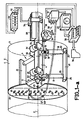
- FIG. 1a and 1b show the exploration device according to the invention.
- the interior volume 1 to be explored is recalled by the drawing of a generator cylinder 2 and of circular cross section 3.
- the exploration device comprises a frame, the elements of which are numbered from 4 to 24.
- This frame essentially comprises a slide 4 supported for example by two sets, respectively 5 and 6, of spacers each comprising three spacers.
- the three spacers of each set are each placed in a different plane and substantially perpendicular to the axis 7 of the cylinder.
- the two planes are about 30 cm apart.
- the spacers are oriented with directions forming between them angles substantially equal to 120 ° .
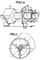
- FIG. 2 schematically shows the position of the spacers 8 and 9 visible in FIG. 1a, and of the spacer 10 which is not shown there.
- These spacers are made integral with the slide 4 at one of their ends, by any means, in particular by means of a pentagonal piece 11 provided with a recess 12 and two faces respectively 13 and 14 to serve as a base for the spacers 8 and 10.
- the recess 12 is used for the translation of the probe holder.
- Each of the six spacers of the frame has an adjustment wheel 15 in the form of a disc.
- One of the faces of each wheel has a threaded endpiece 16 for engaging in a nut 17 fixed to the frame (part 11), while the other face is provided with a smooth cylindrical endpiece 18.
- the endpiece 18 is designed to engage in a hole in the base of a spacer element 19.
- Each spacer element also has at its head an em smooth cylindrical end 20.
- the spacer elements may be of different lengths, and possibly plugged into each other, to constitute a larger spacer. For this reason, the diameters of the end pieces 20 of the spacers are compatible with the holes made in their base.
- the end pieces 20 of the heads of the spacers are designed to be fitted into elementary floors such as 21.
- Each floor has two holes on one face, for example 22 and 23, designed to receive the ends of two spacers, for example 9 and 19, mutually parallel but located in different planes 5 or 6.
- the device of the invention overcomes all the problems of wedging this cylinder on a support.
- the exploration device also includes means for sliding the probe holder 25.
- These means for sliding essentially comprise a shaft 26 of polygonal section, here the section is even square.
- the shaft 26 rests on the slide 4 by means of pads, such as 27 or 28 ( Figure 1b) of sliding without friction. A number of these pads are thus distributed along each bearing face of the slide 4.
- pads such as 27 or 28 ( Figure 1b) of sliding without friction. A number of these pads are thus distributed along each bearing face of the slide 4.
- sets of rollers 29, 30 and 31 , 32 exert a reaction on the upper faces of the shaft 26.
- the axes of the rollers are held integral with the slide. This reaction prevents the shaft 26 from tilting.
- the section of the shaft 26 is preferably polygonal so that the supports and the reactions can be exerted whatever the abscissa position of the shaft 26.
- a strip graduated 33 is fixed on the shaft 26.
- This graduated strip 33 comprises a glass beam provided with stripes, regularly spaced, which scroll, when the shaft 26 slides, in front of an optical encoder 34.
- the optical encoder 34 counts the stripes and allows the abscissa of the end of the shaft 26 to be measured and displayed in a display 35.
- a drum 36 is for example provided integral with a crank 37.
- the crank 37 causes the drum to rotate about an axis 38 substantially orthogonal to the axis 7 and fixed to the slide 4.
- a wire 39, or a cable, is wound a few turns around the drum 36; one of its ends is hooked to a stop 40 integral with the shaft 26, near the probe holder 25, while the other is fixed by means of a tension adjusting screw 41 to an indexing hub 42 also made integral with the shaft 26 at its other end.
- the crank 37 By operating the crank 37, the shaft 26 is made to slide. This sliding is stopped on either side when the stop 40 or the indexing hub 42 comes into contact with the ends of the slide 4.
- the means for pivoting the probe holder 25 about the axis 7 essentially comprise a mandrel 43 (FIGS. 1a and 1b) mounted to rotate freely inside and in the axis of the shaft. 26.
- the mandrel At the rear end (FIG. 1b) the mandrel has a longitudinal notch 44 for receiving a lug 45 of an indexing button 46.
- the indexing button comprises a sliding crown around the mandrel 43 and provided with a or a plurality of pins such as 47. This or these pins 47 are provided to engage in cells 48 made opposite in the indexing hub.
- the cells 48 are distributed there regularly on a ring centered on the axis 7 of the hub.
- the hub 42 is fixed to the end of the shaft 26 by any means, in particular by means of two screws 49 and 50 which engage in holes 51 and 52 respectively of the hub 42.
- the button 46 is pulled back, the lug 45 slides in the notch 44.
- the mandrel 43 is turned by a desired angle, and the button 46 is pushed forward so that the pin 47 comes to engage in a hole 48 chosen in advance.
- the probe holder 25 has pivoted about the axis 7, and is now rotated by a predetermined angle. This angle corresponds to a multiple of the difference between two neighboring cells 48 on the hub 42.
- the probe holder 25 is mounted at the end of the mandrel 43. It comprises a series of housings denoted 55 to 61, regularly distributed radially.
- the housing 55 is located on the axis 7. If the pitch of the distribution of the housings 55 to 61 is insufficiently fine, it is possible to produce another series of housings, 62 to 66, offset radially from those of the first series for increase the smoothness of the exploration step.
- the other series can however also be adapted to an exploration whose radial repair would be different from that of the first series.
- All the elements of the exploration device are made of non-magnetic material.
- the slide 4 and the shaft 26 are made of aluminum; maintenance games his, the floor elements, the drum, the crank, the mandrel etc ... g have a preferably non-magnetic plastics material, in particular that known under the trade name DELRIN.
- the sliding pads 27 and 28 and the rollers 29 to 32 are covered with polytetrafluoroethylene.
- the armature is first installed inside the cylinder 1. To adjust the position of this armature, the procedure is as follows. The crank 37 is actuated so that the stop 40 comes to bear on the slide 4. In this position, the spacers of the clearance 5 are adjusted: those which are closest to the probe holder 25. The adjustment is reached when a point chosen outside of the probe holder 25 can occupy in rotation all equidistant positions of the cylinder 1. To facilitate this operation, the adjustment can be carried out with shims applied on the inside of the cylinder. When the clearance 5 is adjusted, by means of the crank 37, the probe holder 25 is moved until the hub 42 abuts at the other end of the slide 4.
- clearance 5 we then undertake, as for clearance 5 , the adjustment of the spacers of the clearance 6. There is in principle no need to touch up the adjustment of the spacers of the clearance 5. In fact, as much the clearance 5 is the only one concerned in the preceding adjustment, as much the adjustment of the clearance 6 is the only efficient in this case. However, the whole operation can be repeated, taking care to replace the probe holder in the appropriate positions each time.
- the adjustment of the clearance 6 is undertaken while a probe 66 is engaged in one of the housings of the probe holder 25.
- the weight of this probe 66 as well as that of its power cable 67 are thus taken into account for the additional deflection that they bring.
- the cable 67 is brought back towards the rear of the device passing alongside if the probe holder comprises a radial piece or through the probe holder 25 through a hole 68 if it is circular.
- an operator places the probe 66 in a specific housing. It also engages the indexing button 46 in a given position of the indexing hub 42. Then by means of the crank 37, it moves the device along a generator of a cylinder inside the cylinder 1.
- predetermined abscissa by means of a measuring device 69 (in the example mentioned an NMR gaussometer), it measures the value of the corresponding field. This value can be entered in memory in a computer 70 then possibly written on a list 74.
- the operator grasps the indexing button 46, pulls it back and rotates it. , driving with it the mandrel 43, by a predetermined angle.
- the exploration procedure is as follows. While the probe holder is oriented in a desired direction, the operator brings the probe holder to a predetermined abscissa. When this predetermined abscissa is reached, the computer 70 sends a validation instruction to display 35. Then the computer 70 controls the multiplexer 71 in sequence. The multiplexer 71 connects each of the probes in turn to the measuring device 69.
- the computer 70 sends a maneuvering authorization which illuminates an indicator light 72 on the display 35.
- the operator can then move the probe holder again to reach another chosen abscissa. So on each time the computer 70 verifies that the abscissa reached corresponds to a predetermined abscissa and which has been previously introduced into its memory.
- the operation of the crank 37 can be prohibited by the lighting of a light 73 also present on the display 35.
- the computer 70 can for example make flash LED 73.
- the movements of translation and rotation of the probe holder 25 can be motorized and the exploration of the volume of the cylinder can then be carried out automatically under the control of the computer.
- the motorization can preferably use pneumatic means which do not produce a magnetic field.
Landscapes
- Physics & Mathematics (AREA)
- Condensed Matter Physics & Semiconductors (AREA)
- General Physics & Mathematics (AREA)
- Investigating Or Analyzing Materials By The Use Of Magnetic Means (AREA)
- Length Measuring Devices With Unspecified Measuring Means (AREA)
Claims (13)
Applications Claiming Priority (3)
| Application Number | Priority Date | Filing Date | Title |
|---|---|---|---|
| FR8604591A FR2596527B1 (fr) | 1986-04-01 | 1986-04-01 | Dispositif d'exploration du volume interieur d'un cylindre et systeme d'investigation muni de ce dispositif |
| FR8604591 | 1986-04-01 | ||
| PCT/FR1987/000193 WO1988009937A1 (fr) | 1987-06-02 | 1987-06-02 | Dispositif d'exploration du volume interieur d'un cylindre |
Publications (2)
| Publication Number | Publication Date |
|---|---|
| EP0241351A1 EP0241351A1 (de) | 1987-10-14 |
| EP0241351B1 true EP0241351B1 (de) | 1990-03-14 |
Family
ID=26225119
Family Applications (1)
| Application Number | Title | Priority Date | Filing Date |
|---|---|---|---|
| EP19870400704 Expired - Lifetime EP0241351B1 (de) | 1986-04-01 | 1987-03-31 | Vorrichtung zum Explorieren des inneren Volumes eines Zylinders und ein mit einer solchen Vorrichtung versehenes Untersuchungssystem |
Country Status (1)
| Country | Link |
|---|---|
| EP (1) | EP0241351B1 (de) |
Families Citing this family (1)
| Publication number | Priority date | Publication date | Assignee | Title |
|---|---|---|---|---|
| FR2693802B1 (fr) * | 1992-07-17 | 1994-09-16 | Sadis Bruker Spectrospin | Procédé de mesure et d'ajustement des gradients d'un appareil à résonance magnétique nucléaire et dispositif correspondant. |
Family Cites Families (3)
| Publication number | Priority date | Publication date | Assignee | Title |
|---|---|---|---|---|
| GB1452280A (en) * | 1973-03-02 | 1976-10-13 | British United Shoe Machinery | Measuring machines |
| US3984627A (en) * | 1974-04-18 | 1976-10-05 | Andre Galerne | Method and apparatus for examining the interior of a bore hole and/or caisson or the like |
| DE2704396C2 (de) * | 1977-02-03 | 1982-09-23 | Deutsche Forschungs- und Versuchsanstalt für Luft- und Raumfahrt e.V., 5000 Köln | Vorrichtung zur Feinpositionierung einer Trägerstange für eine Sonde o.dgl. |
-
1987
- 1987-03-31 EP EP19870400704 patent/EP0241351B1/de not_active Expired - Lifetime
Also Published As
| Publication number | Publication date |
|---|---|
| EP0241351A1 (de) | 1987-10-14 |
Similar Documents
| Publication | Publication Date | Title |
|---|---|---|
| CA2729190C (fr) | Perfectionnements a la determination d'au moins une grandeur associee au rayonnement electromagnetique d'un objet sous test | |
| EP2776853B1 (de) | Vorrichtung zur messung von strömen in leitungen eines ummantelten kabels eines mehrphasigen netzes | |
| EP1666833B1 (de) | Motorisierter und orientierbarer Messkopf | |
| EP0559560B1 (de) | Anordnung zur verstellbaren Aufhängung für ein Objekt in einem dreidimensionalen Bezugsraum | |
| EP1376056A1 (de) | Modulares System zur Erzeugung einer Referenzebene mittels Laser | |
| EP1598265B1 (de) | Vorrichtung zum Steuern eines geschleppten Unterwasserobjektes | |
| EP0213028A1 (de) | Verfahren und Vorrichtung zur Überprüfung von Stäben eines Stabkreuzes für ein Kernbrennstabbündel | |
| EP0241351B1 (de) | Vorrichtung zum Explorieren des inneren Volumes eines Zylinders und ein mit einer solchen Vorrichtung versehenes Untersuchungssystem | |
| CH617506A5 (de) | ||
| FR2596527A1 (fr) | Dispositif d'exploration du volume interieur d'un cylindre et systeme d'investigation muni de ce dispositif | |
| CA2108185C (fr) | Dispositif support d'une sonde de detection et de localisation de defauts eventuels a l'interieur d'un alesage | |
| EP0058594B1 (de) | Gerät zum gleichzeitigen Einlegen von optischen Fasern in einen strukturierten zylindrischen Tragekörper und Kabelherstellungsvorrichtung mit einem derartigen Gerät | |
| CA1103908A (fr) | Fabrication d'elements de cablage comportant des fibres optiques | |
| EP1672309B1 (de) | Motorisierter und orientierbarer Messkopf | |
| CA2535927C (fr) | Dispositif et procede pour la determination d'au moins une grandeur associee au rayonnement electromagnetique d'un objet sous test | |
| WO1988009937A1 (fr) | Dispositif d'exploration du volume interieur d'un cylindre | |
| CA2314166C (fr) | Dispositif pour le deplacement d'un organe dans un tube allonge depuis une extremite de ce tube | |
| FR2761286A1 (fr) | Positionneur multiaxe | |
| CA2873784C (fr) | Distribution de particules solides dans un reacteur | |
| FR2740688A1 (fr) | Sonde videoendoscopique souple a poignee de commande motorisee | |
| FR2515161A1 (fr) | Dispositif de mesure de course, notamment dispositif de mesure de hauteur pour des appareils elevateurs | |
| EP0654631A1 (de) | Vorrichtung zur Untersuchung des physikalischen Zustandes von Rohrleitungen, die von Menschen erreichbar oder begehbar sind | |
| FR2630419A1 (fr) | Touret et appareil enrouleur-derouleur pour cable a fibre optique | |
| WO2014111660A1 (fr) | Dispositif de mesure de profil interne d'un arbre creux | |
| EP0301941B1 (de) | Vorrichtung zur räumlichen Lagebestimmung eines Modells, insbesondere zur Erforschung seiner Retrodiffusionseigenschaften |
Legal Events
| Date | Code | Title | Description |
|---|---|---|---|
| PUAI | Public reference made under article 153(3) epc to a published international application that has entered the european phase |
Free format text: ORIGINAL CODE: 0009012 |
|
| AK | Designated contracting states |
Kind code of ref document: A1 Designated state(s): CH DE GB LI NL |
|
| 17P | Request for examination filed |
Effective date: 19871109 |
|
| 17Q | First examination report despatched |
Effective date: 19890608 |
|
| RAP1 | Party data changed (applicant data changed or rights of an application transferred) |
Owner name: GENERAL ELECTRIC CGR S.A. |
|
| GRAA | (expected) grant |
Free format text: ORIGINAL CODE: 0009210 |
|
| AK | Designated contracting states |
Kind code of ref document: B1 Designated state(s): CH DE GB LI NL |
|
| GBT | Gb: translation of ep patent filed (gb section 77(6)(a)/1977) | ||
| REF | Corresponds to: |
Ref document number: 3761933 Country of ref document: DE Date of ref document: 19900419 |
|
| PLBE | No opposition filed within time limit |
Free format text: ORIGINAL CODE: 0009261 |
|
| STAA | Information on the status of an ep patent application or granted ep patent |
Free format text: STATUS: NO OPPOSITION FILED WITHIN TIME LIMIT |
|
| 26N | No opposition filed | ||
| PGFP | Annual fee paid to national office [announced via postgrant information from national office to epo] |
Ref country code: DE Payment date: 19940218 Year of fee payment: 8 |
|
| PGFP | Annual fee paid to national office [announced via postgrant information from national office to epo] |
Ref country code: GB Payment date: 19940221 Year of fee payment: 8 |
|
| PGFP | Annual fee paid to national office [announced via postgrant information from national office to epo] |
Ref country code: CH Payment date: 19940330 Year of fee payment: 8 |
|
| PGFP | Annual fee paid to national office [announced via postgrant information from national office to epo] |
Ref country code: NL Payment date: 19940331 Year of fee payment: 8 |
|
| PG25 | Lapsed in a contracting state [announced via postgrant information from national office to epo] |
Ref country code: LI Effective date: 19950331 Ref country code: GB Effective date: 19950331 Ref country code: CH Effective date: 19950331 |
|
| PG25 | Lapsed in a contracting state [announced via postgrant information from national office to epo] |
Ref country code: NL Effective date: 19951001 |
|
| GBPC | Gb: european patent ceased through non-payment of renewal fee |
Effective date: 19950331 |
|
| REG | Reference to a national code |
Ref country code: CH Ref legal event code: PL |
|
| NLV4 | Nl: lapsed or anulled due to non-payment of the annual fee |
Effective date: 19951001 |
|
| PG25 | Lapsed in a contracting state [announced via postgrant information from national office to epo] |
Ref country code: DE Effective date: 19951201 |