EP0241153B1 - Dispositif de commande des déphaseurs - Google Patents
Dispositif de commande des déphaseurs Download PDFInfo
- Publication number
- EP0241153B1 EP0241153B1 EP87302168A EP87302168A EP0241153B1 EP 0241153 B1 EP0241153 B1 EP 0241153B1 EP 87302168 A EP87302168 A EP 87302168A EP 87302168 A EP87302168 A EP 87302168A EP 0241153 B1 EP0241153 B1 EP 0241153B1
- Authority
- EP
- European Patent Office
- Prior art keywords
- frequency
- clock pulses
- radiant energy
- antenna
- phase
- Prior art date
- Legal status (The legal status is an assumption and is not a legal conclusion. Google has not performed a legal analysis and makes no representation as to the accuracy of the status listed.)
- Expired - Lifetime
Links
Images

Classifications
-
- H—ELECTRICITY
- H01—ELECTRIC ELEMENTS
- H01Q—ANTENNAS, i.e. RADIO AERIALS
- H01Q3/00—Arrangements for changing or varying the orientation or the shape of the directional pattern of the waves radiated from an antenna or antenna system
- H01Q3/26—Arrangements for changing or varying the orientation or the shape of the directional pattern of the waves radiated from an antenna or antenna system varying the relative phase or relative amplitude of energisation between two or more active radiating elements; varying the distribution of energy across a radiating aperture
- H01Q3/30—Arrangements for changing or varying the orientation or the shape of the directional pattern of the waves radiated from an antenna or antenna system varying the relative phase or relative amplitude of energisation between two or more active radiating elements; varying the distribution of energy across a radiating aperture varying the relative phase between the radiating elements of an array
- H01Q3/34—Arrangements for changing or varying the orientation or the shape of the directional pattern of the waves radiated from an antenna or antenna system varying the relative phase or relative amplitude of energisation between two or more active radiating elements; varying the distribution of energy across a radiating aperture varying the relative phase between the radiating elements of an array by electrical means
- H01Q3/36—Arrangements for changing or varying the orientation or the shape of the directional pattern of the waves radiated from an antenna or antenna system varying the relative phase or relative amplitude of energisation between two or more active radiating elements; varying the distribution of energy across a radiating aperture varying the relative phase between the radiating elements of an array by electrical means with variable phase-shifters
- H01Q3/38—Arrangements for changing or varying the orientation or the shape of the directional pattern of the waves radiated from an antenna or antenna system varying the relative phase or relative amplitude of energisation between two or more active radiating elements; varying the distribution of energy across a radiating aperture varying the relative phase between the radiating elements of an array by electrical means with variable phase-shifters the phase-shifters being digital
- H01Q3/385—Scan control logics
Definitions
- This invention relates to phased array antennas and, more particularly, to a system for forming a beam of radiation at various frequencies of radiation.
- Arrays of radiating elements are utilized for forming beams of radiant energy for both electromagnetic energy and sonic energy.
- the beams are generally formed by transducers of a sonar system.
- the radiating elements may take the form of dipoles or other form of radiating elements.
- beam-steering units form the beam and direct the beam by the control of delay or phase shift of the radiant energy from one radiating element relative to the radiant energy from a second radiating element of the array.
- the beam may be made to scan across a region of space, or may be made to jump from region to region as in the case of the tracking of targets located in different directions from the antenna.
- a scanning antenna radiating electromagnetic energy as in the case of a phased-array antenna of a microwave landing system for aircraft at an airport.
- a beam scans back and forth to both sides of a runway for use by an incoming aircraft in the generation of guidance signals which guide the aircraft to the runway.
- guidance signals which guide the aircraft to the runway.
- such a beam would be scanned approximately 30° to either side of the runway.
- the beam-steering unit is designed to produce a beam at a specific frequency of electro-magnetic energy.
- MLS microwave landing system
- a beam-steering unit includes a memory for storing data as to the requisite phase shift where phase shifters are utilized, or delay where delay units are utilized, for each radiating element for each direction in which the beam is to be pointed relative to the antenna array.
- phase shifters phase shifters
- delay units delay units
- phase data or delay data would be repeated for a second frequency and for a third frequency, and again for still further frequencies, in the case where the beams are to be formed at different frequencies of radiation.
- the beam-steering unit is able to form and steer the beams at different frequencies of radiation.
- a beam forming system which incorporates the invention to provide for the multiple frequency capability without the need for the additional storage of phase or delay data for each of the frequencies at which the antenna is to radiate. While the invention is equally applicable to systems employing either phase shifters or delay units, the description of the invention is facilitated by considering a specific scanning system utilizing phase shifters.
- the theory of the invention can be understood with reference to the formulation of the amount of phase shift required to direct a beam in a specific angle relative to the array.
- the requisite phase shift is proportional to the spacing between two radiating elements, to the frequency, and to the sine of the angle between the beam and a normal to the array.
- a separate set of date is stored for each angle, and also for each radiating element to accommodate the various distances between one element and its neighbors. It is also noted from the foregoing formulation that a shift in frequency has the same effect as a shift in the sine of the angle.
- the beam-steering unit of the invention commands a value of the sine of an angle other than the one to which the beam is to be pointed.
- the beam actually points in a direction closely approximating the desired angle.
- the invention is most useful in the situation of the scanning beam wherein the scanning takes place, as noted above, by a sequence of stepwise increments of the beam direction.
- a sequence of stepwise increments in the beam direction still results.
- the resultant sequence of steps may be more coarse or more fine than the steps of the original sequence.
- an incoming aircraft still responds as though there is a continuously scanned beam.
- the sine is zero at all frequencies. And for slight deviations in beam direction from the normal to the array, there are relatively small differences in the sine at the various frequencies for which the array is to radiate. However, at relatively large angles of deviation of the normal to the array, such as 30°, the resultant differences in phase shift may have passed through many multiples of 360°, depending on the length of the array relative to a wavelength of the radiation.
- the largest changes in the stepwise increments of beam direction occur for the largest deviations of the beam direction from the normal to the array.
- the changes in the steps become smaller and, accordingly, the beam steering commands essentially "catch up " with the beam-steering commands for radiation at the design frequency.
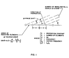
- Figs. 1 and 2A an incident wavefront of radiant energy impinges upon the array of radiating elements from a direction offset from a normal to the array.
- the spacing between the elements of the array, the wavelength, the angle of the direction of propagation, and the phase shift are all identified by symbols shown in Fig. 1. Since the mathematical description of the requisite phase is the same for both an incoming and an outgoing beam of radiation, the description applies equally well to transmitted and received beams.
- Fig. 1 provides the mathematical formulation for the requisite phase shift for each element of the array, the requisite phase shift being dependent on the number of elements between which the phase shift is measured, the frequency of the radiation, and on the sine of the angle of propagation relative to a normal to the array.
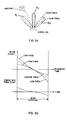
- a shift in frequency or wavelength results in a shift in beam position as depicted in Fig. 2A.
- a shift in frequency without a corresponding change in the command to the phase shifters (to be described subsequently) results in a shifting of the beam position for all beams other than the beam pointing straight ahead of the array.
- Fig. 1 show the effect of beam pointing angle as a function of radiation frequency in terms of center, or midband, values of wavelength and frequency.
- the mathematical relationships show that the sine of the beam pointing angle varies inversely with the radiation frequency.
- Fig. 2A a decrease in radiation frequency from the center frequency offsets the beam away from the center beam position, while an increase in frequency offsets the beam towards the center position. This shift is observed for a fixed value of phase shift.
- a different value of the phase angle produces each of the three beam positions of Fig. 2A.
- Fig. 2A also demonstrates the scanning of a beam for an MLS, the scanned beam being received by an incoming aircraft flying towards the array. While only a few beam positions are shown in Fig. 2A, it is to be understood that many steps of beam scanning are employed, the steps being sufficiently close together such that the incremental changes in direction are less than a beamwidth so that a receiver within the aircraft responds as though there were a continuously moving beam.
- the set of phase-shift commands for each beam direction is indicated by a subscript.
- the resulting beam positions are offset from each other due to a shift in the wavelength and frequency, as noted above.
- the design frequency is set at the highest frequency of interest, with all of the other frequencies which are to be accommodated being at lower frequencies than the design frequency.
- Fig. 2B three graphs are presented in time registration with each other to show beam direction and error as a function of scanning time, as a beam of Fig. 2A is scanned about the antenna array of Fig. 2A.
- the upper graph depicts a variation in beam direction as a function of frequency in the absence of the frequency compensation of the invention.
- a linear scan at the center radiation frequency as a function of scanning time, is indicated by a dashed line.
- a beam at a lower radiation frequency would tend to deflect with a greater angle than is desired and a beam at higher radiation frequency would deflect at a lesser angle than is desired.
- the deflections of the higher and lower frequency beams are indicated by solid lines, and result in a nonlinear error as shown in the second graph.
- the effect of the frequency shift on beam position is compensated by commanding a different value of phase shift as a function of scanning time, and dependent on a selected value of radiation frequency.
- a different value of phase shift as a function of scanning time, and dependent on a selected value of radiation frequency.
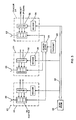
- an antenna array 20 having radiating elements 22 corresponding to the array of the elements of Figs. 1 and 2A.
- the radiating elements 22 are coupled by phasors 24 and a power divider 26 to a transmitter 28.
- the transmitter 28 provides electromagnetic power which is divided by the divider 26 among the respective elements 22.
- the electromagnetic power flows through the phasors 24 which impart the requisite phase shift so that the power radiates from the respective elements 22 with the requisite phase shifts to produce one of the beams shown in Fig. 2A.
- Each of the phasors 24 in the preferred embodiment of the invention is constructed with a digitally operated phase shifter 30 and a counter 32 which provides a multidigit signal to activate the respective sections of the phase-shifter 30.
- a scan PROM 34 (programmable read-only memory) provides signals to each of the counters 32 which increment their respective counts to the required values of phase-shift command.
- Each of the phasors 24 includes a decoder 35 connected between the scan PROM 34 and the counter 32 for decoding a phasor identification signal transmitted by the PROM 34, thereby insuring that the increment command signals of the PROM 34 are properly identified and applied to the respective ones of the phasors 24.
- each of the phasors 24 employ a digital phase-shifter 30 operated by a counter 32
- other circuitry can be utilized for directing the command to the phase shifter 30.
- the counter 32 and the PROM 34 an alternative form of memory could be utilized for applying directly a multi-digit signal to the phase-shifters 30.
- the antenna system employing the invention generates only a scanning beam for an MLS, it has been found useful to employ the counter 32 with the PROM 34 storing sets of commands for incrementing the respective counts of the counters 32 to the required phase-shifts.
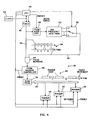
- a beam scanning unit 36 comprises the phasors 24 and the scan PROM 34 previously seen in Fig. 3.
- the unit 36 includes a CPU 38 (central processing unit) and a timer 40 which are driven by a clock 42. Clock pulses from the timer 40 are passed by an AND gate 44 to an address controller 46.
- the address controller 46 includes a counter (not shown), and provides an address to the PROM 34, the address being incremented by the counter of the controller 46 in response to the reception of clock pulses from the gate 44.
- the beam scanning unit 36 further comprises an address controller 48, a PROM 50 storing data with respect to frequency and the sine of the beam pointing angle, and a switch 52 which selects an output terminal of the PROM 50 in response to a control signal from the CPU 38.
- a graph 54 shows two sets of digital signals in temporal registration with each other, the upper set being coupled by the line 56 from the timer 40 to the gate 44 while the signals of the lower set are coupled by the line 58 from the switch 52 to the gate 44.
- a graph 60 describes the digital signals outputted on a bus 62 by the PROM 34, the signals being applied by the bus 62 to respective ones of the phasors 24.
- the CPU 38 provides signals to the timer 40, the phasors 24, the controller 48 and the switch 52 to provide the desired scanning of a beam from the array 20.
- the controller 48 includes a counter (not shown) which increments in response to pulses from the timer 40, the counter providing a sequence of addresses to the PROM 50.
- the memory of the PROM 50 is divided in sections, one section corresponding to the central frequency of each band of received channels to be utilized in the MLS for guiding the aircraft of Fig. 2A. For example, in the usual MLS wherein there are 200 separate receiver channels, it has been found adequate to divide the spectral space into 24 separate bands for transmission by the antenna array 20 of Figs. 2A and 3.
- Each section of the memory of the PROM 50 is set for the center frequency of one of the foregoing frequency bands. All of the sections of the PROM 50 are simultaneously addressed by the controller 48, the address commanding a specific beam angle for directing the beam of Fig. 2A. The individual sections of the PROM 50 have corresponding output terminals of which one is selected by the switch 52.
- the CPU 38 presets the counter of the controller 48 to a desired beam angle after which the addresses provided by the controller 48 are incremented by the timer pulses for stepping the beam of Fig. 2A to provide for the scanning of the beam.
- the data stored in the PROM 50 is of relatively simple form, the data being simply a set of signals designating the increment or non-increment of the counter of the controller 46.
- the resulting clock pulses exiting from the PROM 50 via the switch 52 are of the same form as the pulses of the timer 40, the two sets of pulses differing only in respect to the presence and absence of certain pulses; the two sets of pulses are coupled via the lines 58 and 56 to the AND gate 44.
- the scan PROM 34 stores data with respect to the phase-shift commands for operation of the phasors 24. Since the phasors 24 have been constructed with counters 32, the phase-shift commands provided on bus 62 have the format of a sequence of digital words each of which comprises a field of digits which identify a phasor, followed by a pulse which increments the count of an individual one of the counters 32.
- phase-shifters 30 comprise sections of well-known diode phase-shifters of microwave energy.
- Each section of the phase-shifter 30 includes well-known transmission lines, such as waveguides, having a length equal to an integral number of quarter wavelengths.
- One segment provides phase-shift in increments of 180°, a second section in increments of 90°, and a third section in increments of 45°. While only three sections are shown in the diagram of Fig. 3, it is to be understood that a fourth section having increments of 22.5° is advantageously employed and that, if desired, a still further section for yet finer control of the beam may be utilized.
- the counters 32 count modulo-16.
- the counters 32 include a preset terminal and an up/down terminal for receiving signals from the CPU 38 to designate a starting count and increments therefrom. Thus, by receipt of a specified number of increment pulses along bus 62, a counter 32 can be driven to any desired output count.
- Each output line of the counter 32 carries one digit of the count. Each of these lines is coupled to a corresponding one of the sections of the phase-shifter 30 for driving that section.
- Each output line of the counter 32 provides a logic 1 or a logic 0 depending on the value of the output count.
- the logic 1 signals activate the corresponding sections of the phase-shifter 30 to which the output signals of the counter 32 are applied. Thereby, the microwave signals receive a phase-shift equal to the sum of the phase-shifts introduced by the individual sections of the phase-shifter 30.
- the steps in the scanning direction are sufficiently small such that for any one step the phase shift imparted by any one of the phase shifters 30 may remain unchanged, or may be changed by the smallest phase increment, plus or minus 22.5° in the case of a four-element phase shifter. But such change is never greater than the foregoing smallest phase instrument. Accordingly, the count of a counter 32 of a phasor 24 is never altered by more than a count of one for each stepwise increment in beam position during a scanning of the beam.
- the scan PROM 34 sends simply a logic 1 or logic 0 (in addition to the phasor identity) and the CPU 38 sends an up/down signal to a phasor 24 at each step of a scan.
- the CPU 38 also sends a reset signal to the counter 32 in each phasor 24 for initializing the value of the count at a convenient point in the scanning process. For example, a reset to zero may be employed when the beam passes by the center position, this being zero degrees beam angle, in each sweep of the scan.
- the average repetition frequency of pulses on line 58 is equal to one-half of the repetition frequency of the pulses on line 56 at the design frequency of the beam scanning unit 36.
- pulses may be added to, or deleted from the line 58.
- the pulses on line 58 serve to gate the pulses on the line 56 through the gate 44, the absence of a pulse on line 58 serving to blank the appearance of a pulse on line 56.
- the number of clock pulses on line 56 from the timer 40 which are applied to the controller 46 depends on the presence of a pulse on line 58.
- the PROM 50 along with the controller 48 and the switch 52 would be deleted, and pulses from the timer 40 would be applied at one-half the present rate directly to the controller 46. It is the presence of the PROM 50 with the controller 48 and the switch 52 which apply the gating pulses via the gate 44 that convert a single frequency system to a multiple-frequency beam-scanning unit 36 of the invention.
- the counter in the controller 46 is preset by a signal from the CPU 38 and, thereafter, counts clock pulses supplied by the gate 44. Depending upon whether a wide scan or a narrow scan is desired, the CPU 38 presets the counter of the controller 46 to a desired count for addressing the PROM 34 the count providing the desired beam angle at the start of a scan. Thereafter, the count of the controller 46 is incremented by the clock pulses supplied by the timer 40 via the gate 44 for stepping the beam of Fig. 2A to provide for the scanning of the beam. The CPU 38 also applies an enable signal to the counter of the controller 48 during each scan interval.
- a scan interval terminates upon termination of the enable signal, at which point further addressing of the PROM 50 and further flow of gating pulses on line 58 are terminated.
- the operation of the scan PROM 34 under a control of the controller 46 may be further understood with reference to Figs. 5 and 6.
- the horizontal axis represents increments of time during an interval of scan, each increment of time corresponding to an individual address of the PROM 34.
- the vertical axis represents identification numbers of the phasors 24.
- the entire contents of the PROM 34 is outputted to the phasors 24.
- the PROM 34 advances to the next location on the horizontal axis of Fig. 5 to output incrementing pulses 64 shown stored at various locations in Fig. 5.
- Fig. 6 is a simplified representation of the graph of Fig. 5 with the PROM address being presented on the horizontal axis.
- the controllers 46 and 48 are both preset by the CPU 38 to the address shown at the left side of Fig. 6. Scanning continues until the address at the right side of Fig. 6 is reached.
- the range of addresses is reduced as indicated in Fig. 6.
- the beam tends to deflect through a greater scan angle than is the case for the higher radiation frequency even though the phase angle is the same. Accordingly, the full scan at any frequency is to be attained by using more or less of the stored phase increment commands of Fig.
- the beam-steering unit 36 compensates for changes in frequency of the transmitted radiation by altering the commanded angle to the PROM 34 which, in turn, makes a corresponding change in the commanded phase shift by the phase shifters 30.
- the phasors 24 then institute a phase shift which closely approximates the amount of phase shift actually required to steer the beam to the desired angle at the new frequency of the radiation. While the total number of steps appearing in the incrementally stepped scan may differ as a function of frequency, there are a sufficient number of steps to provide increments in direction which are smaller than a beamwidth so as to provide the appearance of a smoothly scanned beam.
- the foregoing features have been attained by use of only one PROM 34 storing phase shift commands for the single frequency case. The only other stored data required is that of the PROM 50, which date relates to the addressing of the PROM 34 to accomplish the skipping (or addition) of steps to the scan.
Landscapes
- Variable-Direction Aerials And Aerial Arrays (AREA)
Claims (12)
- Structure d'antenne à fréquences multiples conçue pour fonctionner à uns fréquence sélectionnée dans une bande de fréquences présélectionnée qui est définie par une première fréquence et une seconde fréquence, cette structure comprenant :
une antenne-réseau à balayage par déphasage (20);
un ensemble de déphaseurs (24, 30) connectés à des éléments (22) de l'antenne pour communiquer un déphasage à l'énergie rayonnante des éléments;
une mémoire (34) connectée aux déphaseurs pour commander le déphasage de déphaseurs respectifs afin de pointer un faisceau de l'énergie rayonnante à la fréquence sélectionnée selon un angle commandé par rapport à l'antenne;
un circuit d'adresse (46) destiné à adresser la mémoire avec l'angle commandé pour produire le déphasage précité; et
un circuit de modification (38, 48, 50, 52) connecté au circuit d'adresse (46) pour modifier l'adresse conformément à un changement de la fréquence sélectionnée de l'énergie rayonnante;
caractérisée en ce que :
la mémoire (34) enregistre seulement des déphasages qui sont associés à une fréquence prédéterminée dans la bande de fréquences; et
le circuit de modification comprend une mémoire supplémentaire (50) qui enregistre un ensemble de données pour chaque angle entre le faisceau et une normale au réseau et pour chacun des éléments, de façon à modifier l'adresse précitée d'une quantité qui compense pratiquement le changement de la fréquence sélectionnée, afin d'obtenir pratiquement le déphasage exigé pour l'angle de faisceau commandé, pour le rayonnement à la fréquence sélectionnée changée. - Une structure selon la revendication 1, caractérisée en outre par une unité centrale de traitement (UC, 38), connectée au circuit d'adresse pour produire une séquence d'adresses pour un balayage pas à pas du faisceau de rayonnement.
- Structure selon la revendication 2, caractérisée en outre par un générateur de signaux de temps (40) qui est destiné à produire une séquence d'impulsions d'horloge, et dans laquelle le circuit d'adresse est conçu de façon à fonctionner sous la dépendance de la réception des impulsions d'horloge, la mémoire supplémentaire (50) enregistrant des séquences d'impulsions d'horloge qui correspondent à la différence entre la fréquence sélectionnée et la fréquence prédéterminée, un train d'impulsions d'horloge provenant de la mémoire supplémentaire (50) étant associé à un train d'impulsions d'horloge provenant du générateur de signaux de temps, pour réaliser une transmission sélective des impulsions d'horloge du générateur de signaux de temps, afin de modifier la valeur de l'incrémentation du circuit d'adresse.
- Structure selon la revendication 3, caractérisée en ce que le circuit de modification comprend une porte (44) qui est connectée entre le générateur de signaux de temps et le circuit d'adresse, pour réaliser la transmission sélective des impulsions d'horloge du générateur de signaux de temps.
- Structure selon la revendication 4, caractérisée en ce que l'unité centrale est connectée aux déphaseurs et au circuit d'adresse (46) pour prépositionner les déphaseurs et pour prépositionner le circuit d'adresse pour le balayage d'un faisceau d'énergie rayonnante à la fréquence prédéterminée.
- Structure selon la revendication 4, caractérisée en ce que les séquences d'impulsions d'horloge qui sont enregistrées dans la mémoire supplémentaire (50) comprennent un ensemble d'impulsions d'horloge (54) mutuellement espacées avec des espacements temporels différents, le format d'espacement des impulsions d'horloge pour une fréquence d'énergie rayonnante dans la bande de fréquences présélectionnée étant différent du format des impulsions d'horloge pour une autre fréquence de l'énergie rayonnante dans la bande de fréquences présélectionnée, grâce à quoi la fréquence de répétition d'impulsions moyenne de la séquence enregistrée d'impulsions d'horloge à une fréquence de l'énergie rayonnante diffère de la fréquence de répétition d'impulsions moyenne de a séquence enregistrée d'impulsions d'horloge à une autre fréquence de l'énergie rayonnante.
- Structure selon la revendication 6, caractérisée en ce que les changements de direction du faisceau de rayonnement par rapport à l'antenne, qui se produisent à chaque pas du balayage pas à pas, sont inférieurs à la largeur du faisceau, pour donner une approximation d'un faisceau à balayage continu, à un ensemble de fréquences différentes dans la bande de fréquences présélectionnée de l'énergie rayonnante.
- Un procédé de balayage pas à pas pour une antenne-réseau à déphasage par balayage qui est conçue pour fonctionner à une fréquence sélectionnée dans une bande de fréquences présélectionnée qui est définie par une première fréquence et une seconde fréquence, un ensemble de déphaseurs (24, 30) étant connecté à des éléments (22) de l'antenne pour communiquer un déphasage à l'énergie rayonnante des éléments;
caractérisé en ce que :(a) on enregistre dans une mémoire (34) un ensemble d'ordres de déphasage en fonction de l'angle du faisceau pour chacun des déphaseurs, à une fréquence de rayonnement prédéterminée dans la bande de fréquences précitée;(b) on adresse séquentiellement cette mémoire pour effectuer un balayage d'un faisceau à la fréquence de rayonnement prédéterminée de l'antenne; et(c) on modifie l'adressage dans une séquence d'adresses pour le balayage, cette modification étant effectuée en fonction de la différence entre la fréquence prédéterminée et la fréquence sélectionnée de l'énergie rayonnante, dans le but d'introduire une compensation dans la relation du déphasage commandé vis-à-vis de la fréquence sélectionnée, en fonction de l'angle du faisceau. - Un procédé selon la revendication 8, caractérisé en ce que l'adressage est accompli en incrémentant une valeur de comptage d'impulsions d'horloge (40), et dans lequel la modification précitée est accomplie en transmettant sélectivement en sortie (par l'intermédiaire de 44) certaines des impulsions d'horloge, pour produire une fréquence de répétition moyenne d'impulsions d'horloge comptées qui diffère en fonction de la différence entre la fréquence prédéterminée et la fréquence sélectionnée de l'énergie rayonnante de l'antenne.
- Un procédé selon la revendication 9, caractérisé en ce que la transmission sélective est accomplie en enregistrant des séquences d'impulsions d'horloge (54) qui sont espacées avec différentes valeurs d'espacement temporel.
- Un procédé selon la revendication 10, caractérisé en ce que la transmission sélective est accomplie en outre en faisant varier l'espacement temporel des séquences enregistrées en fonction de l'angle de balayage (50), pour donner une cadence d'incrémentation à des fréquences comprises entre les première et seconde fréquences, qui est égale à une cadence d'incrémentation à la fréquence prédéterminée, pour des faisceaux de rayonnement qui sont dirigés pratiquement selon une normale au réseau.
- Un procédé selon la revendication 11, caractérisé en outre en ce qu'on met en oeuvre des ordres de déphasage en comptant des impulsions d'incrémentation d'une séquence de telles impulsions dans un ordre de déphasage enregistré, ce comptage comprenant l'application d'une valeur de comptage résultante à des déphaseurs qui sont connectés à des éléments rayonnants de l'antenne.
Applications Claiming Priority (2)
| Application Number | Priority Date | Filing Date | Title |
|---|---|---|---|
| US06/848,533 US4670756A (en) | 1986-04-07 | 1986-04-07 | Phase shifter control |
| US848533 | 1986-04-07 |
Publications (3)
| Publication Number | Publication Date |
|---|---|
| EP0241153A2 EP0241153A2 (fr) | 1987-10-14 |
| EP0241153A3 EP0241153A3 (en) | 1989-03-29 |
| EP0241153B1 true EP0241153B1 (fr) | 1993-10-20 |
Family
ID=25303550
Family Applications (1)
| Application Number | Title | Priority Date | Filing Date |
|---|---|---|---|
| EP87302168A Expired - Lifetime EP0241153B1 (fr) | 1986-04-07 | 1987-03-13 | Dispositif de commande des déphaseurs |
Country Status (7)
| Country | Link |
|---|---|
| US (1) | US4670756A (fr) |
| EP (1) | EP0241153B1 (fr) |
| JP (1) | JPS62243404A (fr) |
| AU (1) | AU583713B2 (fr) |
| CA (1) | CA1269750A (fr) |
| DE (1) | DE3787824T2 (fr) |
| NZ (1) | NZ219746A (fr) |
Cited By (2)
| Publication number | Priority date | Publication date | Assignee | Title |
|---|---|---|---|---|
| US6538619B2 (en) | 1994-11-04 | 2003-03-25 | Andrew Corporation | Antenna control system |
| US6573875B2 (en) | 2001-02-19 | 2003-06-03 | Andrew Corporation | Antenna system |
Families Citing this family (14)
| Publication number | Priority date | Publication date | Assignee | Title |
|---|---|---|---|---|
| US4811022A (en) * | 1986-10-31 | 1989-03-07 | Cafarelli Nicholas J | Scanning antenna having phase center diversity |
| DE69018906T2 (de) * | 1989-09-11 | 1995-08-24 | Nippon Electric Co | Phasengesteuerte Gruppenantenne mit Temperaturkompensation. |
| US5266953A (en) * | 1991-08-01 | 1993-11-30 | Allied-Signal Inc. | Adaptive fixed-threshold pulse time-of-arrival detection apparatus for precision distance measuring equipment applications |
| US5351053A (en) * | 1993-07-30 | 1994-09-27 | The United States Of America As Represented By The Secretary Of The Air Force | Ultra wideband radar signal processor for electronically scanned arrays |
| KR100468820B1 (ko) * | 1997-08-04 | 2005-03-16 | 삼성전자주식회사 | 가중치기억장치를이용한적응위상배열안테나 |
| US6239744B1 (en) | 1999-06-30 | 2001-05-29 | Radio Frequency Systems, Inc. | Remote tilt antenna system |
| DE19938862C1 (de) | 1999-08-17 | 2001-03-15 | Kathrein Werke Kg | Hochfrequenz-Phasenschieberbaugruppe |
| US6327221B1 (en) * | 1999-09-20 | 2001-12-04 | Honeywell International Inc. | Steered beam ultrasonic sensor for object location and classification |
| DE10104564C1 (de) | 2001-02-01 | 2002-09-19 | Kathrein Werke Kg | Steuerungsvorrichtung zum Einstellen eines unterschiedlichen Absenkwinkels insbesondere von zu einer Basisstation gehörenden Mobilfunkantennen sowie eine zugehörige Antenne und Verfahren zur Veränderung eines Absenkwinkels |
| US6693589B2 (en) * | 2002-01-30 | 2004-02-17 | Raytheon Company | Digital beam stabilization techniques for wide-bandwidth electronically scanned antennas |
| NZ521823A (en) * | 2002-10-04 | 2005-11-25 | Ind Res Ltd | An array of antenna elements used as a microwave sensor to grade produce such as fruit |
| US7557675B2 (en) | 2005-03-22 | 2009-07-07 | Radiacion Y Microondas, S.A. | Broad band mechanical phase shifter |
| US8305751B2 (en) | 2008-04-17 | 2012-11-06 | Teradyne, Inc. | Vibration isolation within disk drive testing systems |
| CN114966557B (zh) * | 2022-05-12 | 2023-04-28 | 浙江铖昌科技股份有限公司 | 一种用于相控阵雷达多通道t/r多功能的快速波控系统 |
Family Cites Families (4)
| Publication number | Priority date | Publication date | Assignee | Title |
|---|---|---|---|---|
| US3887926A (en) * | 1973-11-14 | 1975-06-03 | Singer Co | Phased array scanning antenna |
| US4166274A (en) * | 1978-06-02 | 1979-08-28 | Bell Telephone Laboratories, Incorporated | Techniques for cophasing elements of a phased antenna array |
| US4217587A (en) * | 1978-08-14 | 1980-08-12 | Westinghouse Electric Corp. | Antenna beam steering controller |
| US4445119A (en) * | 1981-04-30 | 1984-04-24 | Raytheon Company | Distributed beam steering computer |
-
1986
- 1986-04-07 US US06/848,533 patent/US4670756A/en not_active Expired - Fee Related
-
1987
- 1987-03-10 AU AU69850/87A patent/AU583713B2/en not_active Ceased
- 1987-03-12 CA CA000531924A patent/CA1269750A/fr not_active Expired - Fee Related
- 1987-03-13 DE DE3787824T patent/DE3787824T2/de not_active Expired - Fee Related
- 1987-03-13 EP EP87302168A patent/EP0241153B1/fr not_active Expired - Lifetime
- 1987-03-24 NZ NZ219746A patent/NZ219746A/xx unknown
- 1987-04-07 JP JP62085604A patent/JPS62243404A/ja active Pending
Cited By (6)
| Publication number | Priority date | Publication date | Assignee | Title |
|---|---|---|---|---|
| US6538619B2 (en) | 1994-11-04 | 2003-03-25 | Andrew Corporation | Antenna control system |
| US6567051B2 (en) | 1994-11-04 | 2003-05-20 | Andrew Corporation | Antenna control system |
| US6603436B2 (en) | 1994-11-04 | 2003-08-05 | Andrew Corporation | Antenna control system |
| US8558739B2 (en) | 1994-11-04 | 2013-10-15 | Andrew Llc | Antenna control system |
| US6573875B2 (en) | 2001-02-19 | 2003-06-03 | Andrew Corporation | Antenna system |
| US6987487B2 (en) | 2001-02-19 | 2006-01-17 | Andrew Corporation | Antenna system |
Also Published As
| Publication number | Publication date |
|---|---|
| AU583713B2 (en) | 1989-05-04 |
| JPS62243404A (ja) | 1987-10-23 |
| US4670756A (en) | 1987-06-02 |
| AU6985087A (en) | 1987-10-08 |
| EP0241153A3 (en) | 1989-03-29 |
| NZ219746A (en) | 1989-08-29 |
| DE3787824T2 (de) | 1994-05-19 |
| EP0241153A2 (fr) | 1987-10-14 |
| CA1269750A (fr) | 1990-05-29 |
| DE3787824D1 (de) | 1993-11-25 |
Similar Documents
| Publication | Publication Date | Title |
|---|---|---|
| US4670756A (en) | Phase shifter control | |
| US4336540A (en) | Radar system | |
| US3448450A (en) | Pulse radar for determining angles of elevation | |
| US4257050A (en) | Large element antenna array with grouped overlapped apertures | |
| US3993999A (en) | Amplitude modulation scanning antenna system | |
| US4178581A (en) | Integrated antenna aperture | |
| US3276023A (en) | Grid array antenna | |
| EP0106494A2 (fr) | Antenne à balayage électronique | |
| US4276551A (en) | Electronically scanned antenna | |
| US3305867A (en) | Antenna array system | |
| US3978482A (en) | Dynamically focused thinned array | |
| US3438035A (en) | Pencil beam frequency/phase scanning system | |
| EP0935761A1 (fr) | Capteur radar a utiliser sur des vehicules a moteur | |
| US3887926A (en) | Phased array scanning antenna | |
| US3286260A (en) | Electronic scanning radar system | |
| US4573050A (en) | Dual scan rate radar | |
| US3864679A (en) | Antenna system for radiating doppler coded pattern using multiple beam antenna | |
| US3484784A (en) | Antenna array duplexing system | |
| WO1991001620A2 (fr) | Systeme d'antenne a elements multiples et procede de traitement de signaux en reseau | |
| US4086597A (en) | Continuous line scanning technique and means for beam port antennas | |
| US4306238A (en) | Microwave landing systems | |
| US6531980B1 (en) | Radar antenna system | |
| US6906665B1 (en) | Cluster beam-forming system and method | |
| US3345631A (en) | Phased array radar antenna scan control | |
| US3878523A (en) | Generation of scanning radio beams |
Legal Events
| Date | Code | Title | Description |
|---|---|---|---|
| PUAI | Public reference made under article 153(3) epc to a published international application that has entered the european phase |
Free format text: ORIGINAL CODE: 0009012 |
|
| AK | Designated contracting states |
Kind code of ref document: A2 Designated state(s): DE FR GB IT NL SE |
|
| PUAL | Search report despatched |
Free format text: ORIGINAL CODE: 0009013 |
|
| AK | Designated contracting states |
Kind code of ref document: A3 Designated state(s): DE FR GB IT NL SE |
|
| 17P | Request for examination filed |
Effective date: 19890919 |
|
| RAP3 | Party data changed (applicant data changed or rights of an application transferred) |
Owner name: HAZELTINE CORPORATION |
|
| 17Q | First examination report despatched |
Effective date: 19920117 |
|
| GRAA | (expected) grant |
Free format text: ORIGINAL CODE: 0009210 |
|
| AK | Designated contracting states |
Kind code of ref document: B1 Designated state(s): DE FR GB IT NL SE |
|
| PG25 | Lapsed in a contracting state [announced via postgrant information from national office to epo] |
Ref country code: SE Effective date: 19931020 |
|
| ITF | It: translation for a ep patent filed | ||
| REF | Corresponds to: |
Ref document number: 3787824 Country of ref document: DE Date of ref document: 19931125 |
|
| ET | Fr: translation filed | ||
| PGFP | Annual fee paid to national office [announced via postgrant information from national office to epo] |
Ref country code: FR Payment date: 19931215 Year of fee payment: 8 |
|
| PGFP | Annual fee paid to national office [announced via postgrant information from national office to epo] |
Ref country code: GB Payment date: 19931223 Year of fee payment: 8 |
|
| PGFP | Annual fee paid to national office [announced via postgrant information from national office to epo] |
Ref country code: NL Payment date: 19940331 Year of fee payment: 8 Ref country code: DE Payment date: 19940331 Year of fee payment: 8 |
|
| PLBE | No opposition filed within time limit |
Free format text: ORIGINAL CODE: 0009261 |
|
| 26N | No opposition filed | ||
| PG25 | Lapsed in a contracting state [announced via postgrant information from national office to epo] |
Ref country code: GB Effective date: 19950313 |
|
| PG25 | Lapsed in a contracting state [announced via postgrant information from national office to epo] |
Ref country code: NL Effective date: 19951001 |
|
| GBPC | Gb: european patent ceased through non-payment of renewal fee |
Effective date: 19950313 |
|
| PG25 | Lapsed in a contracting state [announced via postgrant information from national office to epo] |
Ref country code: FR Free format text: LAPSE BECAUSE OF NON-PAYMENT OF DUE FEES Effective date: 19951130 |
|
| NLV4 | Nl: lapsed or anulled due to non-payment of the annual fee |
Effective date: 19951001 |
|
| PG25 | Lapsed in a contracting state [announced via postgrant information from national office to epo] |
Ref country code: DE Effective date: 19951201 |
|
| REG | Reference to a national code |
Ref country code: FR Ref legal event code: ST |
|
| PG25 | Lapsed in a contracting state [announced via postgrant information from national office to epo] |
Ref country code: IT Free format text: LAPSE BECAUSE OF NON-PAYMENT OF DUE FEES;WARNING: LAPSES OF ITALIAN PATENTS WITH EFFECTIVE DATE BEFORE 2007 MAY HAVE OCCURRED AT ANY TIME BEFORE 2007. THE CORRECT EFFECTIVE DATE MAY BE DIFFERENT FROM THE ONE RECORDED. Effective date: 20050313 |