EP0241076A2 - Drivesystem for weaving looms - Google Patents
Drivesystem for weaving looms Download PDFInfo
- Publication number
- EP0241076A2 EP0241076A2 EP87200551A EP87200551A EP0241076A2 EP 0241076 A2 EP0241076 A2 EP 0241076A2 EP 87200551 A EP87200551 A EP 87200551A EP 87200551 A EP87200551 A EP 87200551A EP 0241076 A2 EP0241076 A2 EP 0241076A2
- Authority
- EP
- European Patent Office
- Prior art keywords
- transmission
- shaft
- auxiliary
- main
- coupling element
- Prior art date
- Legal status (The legal status is an assumption and is not a legal conclusion. Google has not performed a legal analysis and makes no representation as to the accuracy of the status listed.)
- Granted
Links
- 238000009941 weaving Methods 0.000 title claims abstract description 22
- 230000005540 biological transmission Effects 0.000 claims abstract description 105
- 230000008878 coupling Effects 0.000 claims abstract description 84
- 238000010168 coupling process Methods 0.000 claims abstract description 84
- 238000005859 coupling reaction Methods 0.000 claims abstract description 84
- 230000006870 function Effects 0.000 description 6
- 238000010009 beating Methods 0.000 description 4
- 238000001514 detection method Methods 0.000 description 4
- 238000000034 method Methods 0.000 description 3
- 230000000875 corresponding effect Effects 0.000 description 2
- 230000002950 deficient Effects 0.000 description 2
- 239000004744 fabric Substances 0.000 description 2
- 229910052729 chemical element Inorganic materials 0.000 description 1
- 238000005259 measurement Methods 0.000 description 1
Images


Classifications
-
- D—TEXTILES; PAPER
- D03—WEAVING
- D03D—WOVEN FABRICS; METHODS OF WEAVING; LOOMS
- D03D51/00—Driving, starting, or stopping arrangements; Automatic stop motions
- D03D51/02—General arrangements of driving mechanism
-
- D—TEXTILES; PAPER
- D03—WEAVING
- D03D—WOVEN FABRICS; METHODS OF WEAVING; LOOMS
- D03D51/00—Driving, starting, or stopping arrangements; Automatic stop motions
- D03D51/06—Driving, starting, or stopping arrangements; Automatic stop motions using particular methods of stopping
- D03D51/08—Driving, starting, or stopping arrangements; Automatic stop motions using particular methods of stopping stopping at definite point in weaving cycle, or moving to such point after stopping
- D03D51/085—Extraction of defective weft
Definitions
- the present invention concerns a transmission for weaving looms of any kind. More particularly, the invention concerns a transmission comprising a shot search coupling which makes possible to achieve a connection between the auxiliary shaft and the main shaft, whereby this connection between these shafts can occur with a large number of different positions and automatically in function of a previously adjustable parameter.
- the wording "main shaft” is related in this case, as already known, to the shaft which is mainly driving the lathe and, in the case of a gripper weaving loom, is also driving the gripper.
- the main shaft rotates at the same speed as the weaving loom.
- auxiliary shaft means, in this case, as already known, the shaft which is driving the weaving loom parts which are rotating at half speed.
- the auxiliary shaft is mainly driving the frames in this case.
- the present invention is also designed to achieve a transmission whereby the crossing moment of the weaving frames can relatively easily be modified in relationship to the beating moment of the lathe, whereby such operation takes place automatically in function of the adjustment carried out by the weaver after having considered the aspect of the woven cloth.
- the auxiliary shaft of the weaving loom which is mainly driving the frames, as already reported, whereas the main shaft is mainly driving the lathe and can manually be adjusted in order to modify the crossing moment.
- This operation is achieved, for instance, by means of a belt pulley or of a that which is rotated in relation with the shaft after loosening the clamp connection or, for instance, to shift a toothed-belt over a few teeth or, in the case, of a gear transmission, to shift the toothed gears over a few teeth in relationship to each other and to get them engaged afterwards.
- this method implies time losses for thess mounting and assembling operations.
- the objective of the present invention is thus to foresee a transmission for weaving loom, whereby the crossing moment can be modified in relationship with the beating movement of the lathe and whereby this occurs according to the invention by means of the fully automatic switching-on of the shot search coupling in function of a set value.
- Another objective of the invention comprises the fact that the shaft whereon the coupling element of the shot search coupling is mounted must not necessarily rotate at the weaving loom speed or the shaft speed.
- the coupling element of the shot search coupling is mounted on a shaft which is normally rotating at a larger speed than the speed of the main shaft. This system is advantageous because, owing to the larger speed of the coupling element, a smaller rotation moment must be applied to this latter one.
- Still another advantage of this embodiment whereby the coupling element of the shot search coupling is rotating at a larger speed than the main shaft is related to the fact that such a shot search coupling system is specially suitable to achieve the automation reported hereabove.
- the transmission for weaving looms in accordance with the invention comprises the combination of a main shaft transmission, of an auxiliary transmission, of a main shaft, of an auxiliary shaft and of a shot search coupling that can achieve the connection or disconnection between the main shaft and the auxiliary shaft, whereby the connection can occur for a large number of mutually different positions of the main shaft and of the auxiliary shaft; of detection means for determining the angular difference between the positions of the main shaft and of the auxiliary shaft; and of a control unit thath controls the shot search coupling and at last one of the transmissions and this way creates an automatic connection between the main shaft and the auxiliary shaft in function of a set value of this angular difference.
- the shot search coupling used to this end will preferably be equipped with a coupling element that is mounted on a shaft rotating at a larger speed, than the main shaft and the auxiliary shaft.
- the shot search coupling will be preferably composed of a coupling element, the first part of which is connected by means of a first transmission with the main shaft of the weaving loom and the second part of which is connected by means of a second transmission with the auxiliary shaft, whereby the transmission ratios of both transmissions are chosen in such a way that the coupling element has a larger working speed than the working speeds of the main shaft and of the auxiliary shaft.
- the coupling element is running a larger number of revolutions than the main shaft and the auxiliary shaft, the advantage is achieved that a large number of selections for the mutual connection of the main shaft and of the auxiliary shaft are made possible also if the aforesaid coupling element is made of a clutch coupling that has an inherently limited number of gripping capabilities.
- the main transmission and the auxiliary transmission will be preferably mounted respectively along both sides of the coupling element. This way a central location of both transmissions is obtained between the aforesaid first and second transmissions. Such a central position is advantageous because the main transmission, the auxiliary transmission, the coupling element of the shot search coupling, and possibly a break can be included within one single assembly. To this end an electro-magnetic coupling can be used for achieving the necessary mutual connections between the various parts. Such a coupling is described in a separate patent application of the applicant.
- the transmission for weaving looms is mainly composed of a main transmission 1, of an auxiliary transmission 2, of a main shaft 3 that is driving the lathe and possibly the gripper transmission in the case of a gripper weaving loom, an auxiliary shaft 4 that is driving the frames and a shot search coupling 5.
- the shot search coupling 5 renders possible to disconnect the main shaft 3 and the auxiliary shaft 4 while the frames can be moved only by means of the auxiliary shaft 4 that is driven by the auxiliary transmission 2.
- a shot search coupling 5 is used which makes possible to achieve mutual connection of the main shaft 3 and of the auxiliary shaft 4 following a large number of different mutual annular positions, whereby, as schematically illustrated on figure 1, switching-on is automatically achieved by means of a control unit 6 and in such a way that the shot search coupling 5 is achieving the connection between the main shaft 3 and the auxiliary shaft 4 in function of a set value.
- detection means are mounted to this end on the main shaft 3 and the auxiliary shaft 4, and are composed for instance of angle meters.
- the data from these detection means 7 and 8 are supplied through the measuring lines 9 and 10 to the control unit 6.
- control lines 11 and 12 are running from the control unit 6 to, on the one hand, the auxiliary transmission 2 and possibly the main transmission 1 and, on the other hand, to a switching-on mechanism which is not illustrated on the figures for switching-on or off the coupling element 13, properly speaking, of the shot search coupling 5.
- a setting signal 14 can be also applied to the control unit 6 whereby this signal is indicating the desirable difference between the positions of the main shaft 3 and of the auxiliary shaft 4 at the moment of the next switching-on of the shot search coupling 5.
- the ratio shall be interrupted this way if an unadequate adjustment of the weaving loom is carried out.
- the coupling element 13 is switched off and the auxiliary shaft is kept rotating by means of the auxiliary transmission 2 until the appropriate weft thread is introduced at the right time into the shed, with other words the auxiliary shaft is brought to the correct position towards the main shaft.
- an angle is set on the control unit 6 and the auxiliary transmission 2 will be automatically kept switched on by means of this control unit 6 until the correct switching condition is obtained whereby this result is achieved by means of the measurements which are carried out by the detection means 7 and 8.
- the coupling element 13 is automatically switched-on.
- Figures 2 to 6 are illustrating by way of examples a few preferred embodiments of the transmission and which are equipped with shot search couplings 5 and which are particularly suitable for establishing an automatic connection with a large number of positions and which still have a lot of different other advantages.
- the shot search coupling 5 which is considered in this case is mainly composed of a coupling element 13 the first part 15 of which is connected to the main shaft 3 by means of a first transmission 16 and the second part 17 of this coupling element 13 is connected with the auxiliary shaft 4 by means of a second transmission 18 whereby the transmission ratios of both transmissions are chosen in such a way that, when the coupling element 13 is switched-on, the latter one will run at a larger speed than the speeds of the main shaft 3 and of the auxiliary shaft 4.
- the transmission ratios 16 and 18 will be generally chosen respecmerelytive to each other in such a way that, as already known, the main shaft 3 is rotating in the normal working conditions of the weaving loom at a speed which is twice as large as the revolution speed of the auxiliary shaft 4.
- the coupling element 13 is mounted on the shaft 19 that is made of two shaft parts 20 and 21, which are equipped on their ends facing each other of the aforesaid first and second part, respectively 15 and 17 of the coupling element 13.
- the main transmission 1 and the auxiliary transmission 2 are respectively mounted on the shaft parts 20 and 21 and in such a way that they are located between the corresponding coupling parts, respectively 15 and 17, and the transmissions 16 and 18. This way, we get the advantage that the whole system made of the transmissions 1 and 2 and of the coupling element 13 can be designed as a compact assembly 22.
- Another advantage is related to the fact that the transmission 1 and 2 are centrally mounted between the main shaft 3 and the auxiliary shaft 4 whereby the number of couplings in the transmissions is kept limited.
- the aforesaid assembly 22 may be equipped preferably of an electro-magnetic coupling which makes possible that either the main transmission 1 or the auxiliary transmission 2 or a break not illustrated on the figures can be switched on.
- the transmission 18 is composed in the embodiment according to figure 2 of the combination of a gear coupling 23 comprising two conical gears 24 and 25 and a belt transmission 26.
- the aforesaid coupling element 13 is made in this case, for instance, of a clutch coupling which has a relatively large number of gripping elements.
- the functioning of the transmission in accordance with figure 2 includes that, in case of break of thread, the main transmission 1 is switched-off, and the aforesaid thread is actuated. This way, the main shaft, as well as the auxiliary shaft are set within a short time. Then the coupling element 13 is disconnected and the defective thread is eliminated.
- the shaft part 21 is first rotated back by means of the auxiliary transmission 2 in such a way that the auxiliary shaft 4 is brought to a position corresponding to the set value supplied to the control unit. Such is automatically occurring by means of the detectors 7 and 8 and of the control unit 6.
- control unit 6 causes the switching-off of the auxiliary transmission 2, the switching-on of the coupling element 13 and finally the switching-on of the main transmission 1.
- auxiliary transmission 2 means a transmission designed to achieve slow running of the weaving loom.
- Figure 3 is illustrating an alternative solution of the embodiment according to figure 2.
- the transmission 18 is made, on the one hand, of a conventional gear transmission while, on the other hand, the main transmission 1 and the auxiliary transmission 2 are mounted in a common system and can co-operate with the shaft part 21.
- the main transmission 1 and the auxiliary transmission 2 can be implemented on quite different ways. According to a preferred embodiment, these elements are made of a given number of coupling parts, of an electro-magnetic coupling, whereby a brake is also foreseen and whereby separate coupling parts are used for the main transmission 1 and for the auxiliary transmission 2, these parts being respectively connected to a main motor and to an auxiliary motor.
- the main transmission 1 and the auxiliary transmission 2, according to the embodiment of figure 3, can be also made of a motor running at the normal speed, as well as at the slow-run speed, whereby brake actuation can also be foreseen.
- FIG 4 is illustrating still another alternative solution of the transmission in accordance with the invention, whereby the coupling element 13 is cooperating with a gear 27 of the aforesaid transmission 16.
- the shaft 19 is equipped with a threaded end 28 in such a way that the gear 27 can be axially shifted towards the end 28 by means of an adequate notch 29.
- connection and the disconnection of the coupling element 13 are achieved in this case, for instance, by axially shifting the gear 27 until the transmission 16 is interrupted. This result is indeed automatically achieved by means of a switching mechanism not illustrated on figure 4 and that is actuated by the control unit 6.
- the aforesaid first 15 and the second part 17 of the coupling element 13 are made in this case of the gears of the transmission 16.
- additional couplings 30 and 31 can also be used in order to get the main transmission 1 and the auxiliary transmission 2 co-operating respectively with the gears 32 and 33 of the aforesaid transmissions 16 and 18. This way, it becomes possible to use transmissions 1 and 2 as well as motors having a large speed. Consequently, the moments applied to the motors can be kept limited.
- the additional transmission 31 between the auxiliary transmission 2 and the aforesaid shaft 19 offers the possibility to foresee a second coupling element 34, whereby the auxiliary transmission 2 can be completely loosened.
- This coupling element 34 can be designed for instance in the same way as the coupling element 13 already illustrated on figures 5 and 6.
- all aforesaid transmissions 16, 18, 30 and 31 may be made of gears, belts, conical gears or combination of these elements.
- the shot search coupling 5 and more particularly the coupling element 13 must not necessarily be a clutch coupling and may also be made for instance of a continuously connectable coupling element.
- All aforesaid embodiments can be foreseen with a locking device prohibiting rotation and mounted on the main shaft 3, whereby this device can be switched-on or switched-off.
Landscapes
- Engineering & Computer Science (AREA)
- Textile Engineering (AREA)
- Looms (AREA)
Abstract
Description
- The present invention concerns a transmission for weaving looms of any kind. More particularly, the invention concerns a transmission comprising a shot search coupling which makes possible to achieve a connection between the auxiliary shaft and the main shaft, whereby this connection between these shafts can occur with a large number of different positions and automatically in function of a previously adjustable parameter. The wording "main shaft" is related in this case, as already known, to the shaft which is mainly driving the lathe and, in the case of a gripper weaving loom, is also driving the gripper. The main shaft rotates at the same speed as the weaving loom. The wording "auxiliary shaft" means, in this case, as already known, the shaft which is driving the weaving loom parts which are rotating at half speed. The auxiliary shaft is mainly driving the frames in this case.
- The present invention is also designed to achieve a transmission whereby the crossing moment of the weaving frames can relatively easily be modified in relationship to the beating moment of the lathe, whereby such operation takes place automatically in function of the adjustment carried out by the weaver after having considered the aspect of the woven cloth.
- It is indeed already known that the crossing moment related to the beating moment of the lathe is a decisive factor in weaving looms as far as the aspect of the woven cloth is concerned. Consequently, it is necessary to be able to adjust these values, whereby fine adjustment should be preferably possible.
- According to a well-known method, the auxiliary shaft of the weaving loom which is mainly driving the frames, as already reported, whereas the main shaft is mainly driving the lathe and can manually be adjusted in order to modify the crossing moment. This operation is achieved, for instance, by means of a belt pulley or of a that which is rotated in relation with the shaft after loosening the clamp connection or, for instance, to shift a toothed-belt over a few teeth or, in the case, of a gear transmission, to shift the toothed gears over a few teeth in relationship to each other and to get them engaged afterwards. Quite obviously this method implies time losses for thess mounting and assembling operations.
- It is also well known that, for shot search couplings, methods are designed, whereby the main shaft and the auxiliary shaft are always engaging each other without erroneous mutual rotation. To this end, clutch couplings are used which make coupling possible only for a specific mutual position of the main shaft and of the auxiliary shaft. Quite obviously, such shot search couplings have the disadvantage that they don't make possible to automatically adjust the crossing moment of the frames.
- The objective of the present invention is thus to foresee a transmission for weaving loom, whereby the crossing moment can be modified in relationship with the beating movement of the lathe and whereby this occurs according to the invention by means of the fully automatic switching-on of the shot search coupling in function of a set value.
- Another objective of the invention comprises the fact that the shaft whereon the coupling element of the shot search coupling is mounted must not necessarily rotate at the weaving loom speed or the shaft speed. According to a preferred embodiment of the invention, the coupling element of the shot search coupling is mounted on a shaft which is normally rotating at a larger speed than the speed of the main shaft. This system is advantageous because, owing to the larger speed of the coupling element, a smaller rotation moment must be applied to this latter one. Still another advantage of this embodiment whereby the coupling element of the shot search coupling is rotating at a larger speed than the main shaft is related to the fact that such a shot search coupling system is specially suitable to achieve the automation reported hereabove.
- To this end, the transmission for weaving looms in accordance with the invention comprises the combination of a main shaft transmission, of an auxiliary transmission, of a main shaft, of an auxiliary shaft and of a shot search coupling that can achieve the connection or disconnection between the main shaft and the auxiliary shaft, whereby the connection can occur for a large number of mutually different positions of the main shaft and of the auxiliary shaft; of detection means for determining the angular difference between the positions of the main shaft and of the auxiliary shaft; and of a control unit thath controls the shot search coupling and at last one of the transmissions and this way creates an automatic connection between the main shaft and the auxiliary shaft in function of a set value of this angular difference.
- The shot search coupling used to this end will preferably be equipped with a coupling element that is mounted on a shaft rotating at a larger speed, than the main shaft and the auxiliary shaft. To this end, the shot search coupling will be preferably composed of a coupling element, the first part of which is connected by means of a first transmission with the main shaft of the weaving loom and the second part of which is connected by means of a second transmission with the auxiliary shaft, whereby the transmission ratios of both transmissions are chosen in such a way that the coupling element has a larger working speed than the working speeds of the main shaft and of the auxiliary shaft. Quite obviously, owing to the fact that the coupling element is running a larger number of revolutions than the main shaft and the auxiliary shaft, the advantage is achieved that a large number of selections for the mutual connection of the main shaft and of the auxiliary shaft are made possible also if the aforesaid coupling element is made of a clutch coupling that has an inherently limited number of gripping capabilities.
- The main transmission and the auxiliary transmission will be preferably mounted respectively along both sides of the coupling element. This way a central location of both transmissions is obtained between the aforesaid first and second transmissions. Such a central position is advantageous because the main transmission, the auxiliary transmission, the coupling element of the shot search coupling, and possibly a break can be included within one single assembly. To this end an electro-magnetic coupling can be used for achieving the necessary mutual connections between the various parts. Such a coupling is described in a separate patent application of the applicant.
- In order to achieve better understanding of the characteristics of the invention a few preferred embodiments will be described hereafter by way of examples without any limitative character and with reference to the figures in appendix which are respectively:
- figure 1 a schematic view of the transmission in accordance with the invention;
- figure 2 a view of one embodiment of the invention whereby the main transmission and the auxiliary transmission, as well as the coupling element of the shot search coupling are mounted on a shaft that is rotating at a larger speed than the main shaft and the auxiliary shaft;
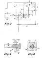
- figure 3 illustrates an alternative solution of the transmission in accordance with the invention;
- figure 4 illustrates still another alternative solution of the transmission in accordance with the invention;
- figure 5 is a magnification of a part of figure 4 which is indicated by F5;
- figure 6 is a cross-section following the line VI-VI of figure 5.
- As illustrated on the figures, the transmission for weaving looms is mainly composed of a
main transmission 1, of anauxiliary transmission 2, of amain shaft 3 that is driving the lathe and possibly the gripper transmission in the case of a gripper weaving loom, anauxiliary shaft 4 that is driving the frames and ashot search coupling 5. Theshot search coupling 5 renders possible to disconnect themain shaft 3 and theauxiliary shaft 4 while the frames can be moved only by means of theauxiliary shaft 4 that is driven by theauxiliary transmission 2. - According to the present invention a
shot search coupling 5 is used which makes possible to achieve mutual connection of themain shaft 3 and of theauxiliary shaft 4 following a large number of different mutual annular positions, whereby, as schematically illustrated on figure 1, switching-on is automatically achieved by means of acontrol unit 6 and in such a way that theshot search coupling 5 is achieving the connection between themain shaft 3 and theauxiliary shaft 4 in function of a set value. - As illustrated on figures 1 to 4, detection means, respectively 7 and 8, are mounted to this end on the
main shaft 3 and theauxiliary shaft 4, and are composed for instance of angle meters. The data from these detection means 7 and 8 are supplied through themeasuring lines control unit 6. - On the other hand,
control lines control unit 6 to, on the one hand, theauxiliary transmission 2 and possibly themain transmission 1 and, on the other hand, to a switching-on mechanism which is not illustrated on the figures for switching-on or off thecoupling element 13, properly speaking, of theshot search coupling 5. Moreover, asetting signal 14 can be also applied to thecontrol unit 6 whereby this signal is indicating the desirable difference between the positions of themain shaft 3 and of theauxiliary shaft 4 at the moment of the next switching-on of theshot search coupling 5. - The function of the transmission in accordance with the invention occurs mainly as described hereafter. If in case of break of a weft or chain thread the machine is stopped on a known manner and the defective thread is pulled from the shed.
- Quite obviously, the ratio shall be interrupted this way if an unadequate adjustment of the weaving loom is carried out. To this end and as already known, the
coupling element 13 is switched off and the auxiliary shaft is kept rotating by means of theauxiliary transmission 2 until the appropriate weft thread is introduced at the right time into the shed, with other words the auxiliary shaft is brought to the correct position towards the main shaft. According to the present invention an angle is set on thecontrol unit 6 and theauxiliary transmission 2 will be automatically kept switched on by means of thiscontrol unit 6 until the correct switching condition is obtained whereby this result is achieved by means of the measurements which are carried out by the detection means 7 and 8. At the moment that the right mutual position of themain shaft 7 and of theauxiliary shaft 8 is achieved, thecoupling element 13 is automatically switched-on. - Quite obviously, the use of a
shot search coupling 5 that makes possible to mutually connect themain shaft 3 and theauxiliary shaft 4 according to a large number of different mutual positions and, on the other hand, the use of acontrol unit 6 renders super fluous the manual adjustments with the advantage that the crossing moment of the frames can easily be modified in relationship to the beating moment. - Figures 2 to 6 are illustrating by way of examples a few preferred embodiments of the transmission and which are equipped with
shot search couplings 5 and which are particularly suitable for establishing an automatic connection with a large number of positions and which still have a lot of different other advantages. - The
shot search coupling 5 which is considered in this case is mainly composed of acoupling element 13 thefirst part 15 of which is connected to themain shaft 3 by means of afirst transmission 16 and thesecond part 17 of thiscoupling element 13 is connected with theauxiliary shaft 4 by means of asecond transmission 18 whereby the transmission ratios of both transmissions are chosen in such a way that, when thecoupling element 13 is switched-on, the latter one will run at a larger speed than the speeds of themain shaft 3 and of theauxiliary shaft 4. - The
transmission ratios main shaft 3 is rotating in the normal working conditions of the weaving loom at a speed which is twice as large as the revolution speed of theauxiliary shaft 4. - In the embodiment according to figure 2, the
coupling element 13 is mounted on theshaft 19 that is made of twoshaft parts coupling element 13. Themain transmission 1 and theauxiliary transmission 2 are respectively mounted on theshaft parts transmissions transmissions coupling element 13 can be designed as acompact assembly 22. Another advantage is related to the fact that thetransmission main shaft 3 and theauxiliary shaft 4 whereby the number of couplings in the transmissions is kept limited. - The
aforesaid assembly 22 may be equipped preferably of an electro-magnetic coupling which makes possible that either themain transmission 1 or theauxiliary transmission 2 or a break not illustrated on the figures can be switched on. - The
transmission 18 is composed in the embodiment according to figure 2 of the combination of agear coupling 23 comprising twoconical gears belt transmission 26. Theaforesaid coupling element 13 is made in this case, for instance, of a clutch coupling which has a relatively large number of gripping elements. - The functioning of the transmission in accordance with figure 2 includes that, in case of break of thread, the
main transmission 1 is switched-off, and the aforesaid thread is actuated. This way, the main shaft, as well as the auxiliary shaft are set within a short time. Then thecoupling element 13 is disconnected and the defective thread is eliminated. - When the weaving loom is switched-on again, the
shaft part 21 is first rotated back by means of theauxiliary transmission 2 in such a way that theauxiliary shaft 4 is brought to a position corresponding to the set value supplied to the control unit. Such is automatically occurring by means of thedetectors control unit 6. - Afterwards, the
control unit 6 causes the switching-off of theauxiliary transmission 2, the switching-on of thecoupling element 13 and finally the switching-on of themain transmission 1. - Quite obviously, the word
auxiliary transmission 2 means a transmission designed to achieve slow running of the weaving loom. - It is also obvious that, in the case of a
shot search coupling 5, as illustrated on figure 2, thecoupling element 13 is running a larger number of revolutions compared with themain shaft 3 and theauxiliary shaft 4. This gives the advantage that themain shaft 3 and theauxiliary shaft 4 can be connected to each other with a large number of possibilities and that this embodiment is particularly suitable for achieving an automated transmission. - Figure 3 is illustrating an alternative solution of the embodiment according to figure 2. In this case, the
transmission 18 is made, on the one hand, of a conventional gear transmission while, on the other hand, themain transmission 1 and theauxiliary transmission 2 are mounted in a common system and can co-operate with theshaft part 21. Themain transmission 1 and theauxiliary transmission 2 can be implemented on quite different ways. According to a preferred embodiment, these elements are made of a given number of coupling parts, of an electro-magnetic coupling, whereby a brake is also foreseen and whereby separate coupling parts are used for themain transmission 1 and for theauxiliary transmission 2, these parts being respectively connected to a main motor and to an auxiliary motor. - Quite obviously, the
main transmission 1 and theauxiliary transmission 2, according to the embodiment of figure 3, can be also made of a motor running at the normal speed, as well as at the slow-run speed, whereby brake actuation can also be foreseen. - The working of the transmission according to figure 3 is essentially similar to that of figure 2 and can also easily be understood by looking at the figure.
- Figure 4 is illustrating still another alternative solution of the transmission in accordance with the invention, whereby the
coupling element 13 is cooperating with agear 27 of theaforesaid transmission 16. As illustrated in details of figures 5 and 6 theshaft 19 is equipped with a threadedend 28 in such a way that thegear 27 can be axially shifted towards theend 28 by means of anadequate notch 29. - The connection and the disconnection of the
coupling element 13 are achieved in this case, for instance, by axially shifting thegear 27 until thetransmission 16 is interrupted. This result is indeed automatically achieved by means of a switching mechanism not illustrated on figure 4 and that is actuated by thecontrol unit 6. The aforesaid first 15 and thesecond part 17 of thecoupling element 13 are made in this case of the gears of thetransmission 16. - As also illustrated on figure 4,
additional couplings main transmission 1 and theauxiliary transmission 2 co-operating respectively with thegears aforesaid transmissions transmissions - The
additional transmission 31 between theauxiliary transmission 2 and theaforesaid shaft 19 offers the possibility to foresee asecond coupling element 34, whereby theauxiliary transmission 2 can be completely loosened. Thiscoupling element 34 can be designed for instance in the same way as thecoupling element 13 already illustrated on figures 5 and 6. - Quite obviously, all
aforesaid transmissions shot search coupling 5 and more particularly thecoupling element 13 must not necessarily be a clutch coupling and may also be made for instance of a continuously connectable coupling element. - All aforesaid embodiments can be foreseen with a locking device prohibiting rotation and mounted on the
main shaft 3, whereby this device can be switched-on or switched-off. - The present invention is by no means limited to the embodiments described by way of examples and illustrated by the figures in appendix but this transmission may also be used for weaving looms and for their shot search coupling with any shape and size without departing from the scope of the invention.
Claims (6)
Applications Claiming Priority (2)
| Application Number | Priority Date | Filing Date | Title |
|---|---|---|---|
| NL8600870A NL8600870A (en) | 1986-04-07 | 1986-04-07 | DRIVE FOR WEAVING MACHINES. |
| NL8600870 | 1986-04-07 |
Publications (3)
| Publication Number | Publication Date |
|---|---|
| EP0241076A2 true EP0241076A2 (en) | 1987-10-14 |
| EP0241076A3 EP0241076A3 (en) | 1990-05-09 |
| EP0241076B1 EP0241076B1 (en) | 1993-08-18 |
Family
ID=19847836
Family Applications (1)
| Application Number | Title | Priority Date | Filing Date |
|---|---|---|---|
| EP87200551A Expired - Lifetime EP0241076B1 (en) | 1986-04-07 | 1987-03-25 | Drivesystem for weaving looms |
Country Status (4)
| Country | Link |
|---|---|
| US (1) | US4874018A (en) |
| EP (1) | EP0241076B1 (en) |
| DE (1) | DE3787039T2 (en) |
| NL (1) | NL8600870A (en) |
Cited By (4)
| Publication number | Priority date | Publication date | Assignee | Title |
|---|---|---|---|---|
| FR2660672A1 (en) * | 1990-04-06 | 1991-10-11 | Staubli Sa Ets | System for driving a machine for forming the shed on a weaving machine |
| EP0736622A1 (en) * | 1995-04-05 | 1996-10-09 | STAUBLI FAVERGES, Société Anonyme | Driving system for shedding mechanisms on looms |
| EP0743383A1 (en) * | 1995-05-12 | 1996-11-20 | Tsudakoma Kogyo Kabushiki Kaisha | Loom drive mechanism |
| EP0799920A1 (en) * | 1996-04-04 | 1997-10-08 | Sulzer RàTi Ag | Jacquard loom and method of operating said loom |
Families Citing this family (2)
| Publication number | Priority date | Publication date | Assignee | Title |
|---|---|---|---|---|
| BE1010849A3 (en) * | 1997-01-14 | 1999-02-02 | Picanol Nv | DRIVE for a weaving machine. |
| EP1312709B1 (en) * | 2001-11-20 | 2007-06-20 | Promatech S.p.A. | Weaving loom with an assembly for actuating the weaving mechanism |
Citations (4)
| Publication number | Priority date | Publication date | Assignee | Title |
|---|---|---|---|---|
| DE2353590A1 (en) * | 1972-11-02 | 1974-05-16 | Elitex Zavody Textilniho | SHOT LOOKING DEVICE, IN PARTICULAR FOR SHEEP MACHINERY OF LOOMS |
| US4424835A (en) * | 1980-10-28 | 1984-01-10 | Ruti-Te Strake B.V. | Weaving error correction device for shuttleless weaving machine |
| US4474219A (en) * | 1982-01-29 | 1984-10-02 | Societe Des Etablissements Staubli (France) | Shed locating devices associated with dobbies and other weaving systems |
| EP0161012A1 (en) * | 1984-04-06 | 1985-11-13 | Picanol N.V. | Shot seeking mechanism for weaving looms |
Family Cites Families (3)
| Publication number | Priority date | Publication date | Assignee | Title |
|---|---|---|---|---|
| JPS59192752A (en) * | 1983-04-13 | 1984-11-01 | 株式会社豊田自動織機製作所 | Constant position stopping control in loom |
| DE3481720D1 (en) * | 1983-12-28 | 1990-04-26 | Nissan Motor | WEAVING MACHINE. |
| CH671591A5 (en) * | 1985-01-17 | 1989-09-15 | Textilma Ag |
-
1986
- 1986-04-07 NL NL8600870A patent/NL8600870A/en not_active Application Discontinuation
-
1987
- 1987-03-25 EP EP87200551A patent/EP0241076B1/en not_active Expired - Lifetime
- 1987-03-25 DE DE87200551T patent/DE3787039T2/en not_active Expired - Lifetime
-
1989
- 1989-02-21 US US07/312,389 patent/US4874018A/en not_active Expired - Lifetime
Patent Citations (4)
| Publication number | Priority date | Publication date | Assignee | Title |
|---|---|---|---|---|
| DE2353590A1 (en) * | 1972-11-02 | 1974-05-16 | Elitex Zavody Textilniho | SHOT LOOKING DEVICE, IN PARTICULAR FOR SHEEP MACHINERY OF LOOMS |
| US4424835A (en) * | 1980-10-28 | 1984-01-10 | Ruti-Te Strake B.V. | Weaving error correction device for shuttleless weaving machine |
| US4474219A (en) * | 1982-01-29 | 1984-10-02 | Societe Des Etablissements Staubli (France) | Shed locating devices associated with dobbies and other weaving systems |
| EP0161012A1 (en) * | 1984-04-06 | 1985-11-13 | Picanol N.V. | Shot seeking mechanism for weaving looms |
Cited By (6)
| Publication number | Priority date | Publication date | Assignee | Title |
|---|---|---|---|---|
| FR2660672A1 (en) * | 1990-04-06 | 1991-10-11 | Staubli Sa Ets | System for driving a machine for forming the shed on a weaving machine |
| EP0736622A1 (en) * | 1995-04-05 | 1996-10-09 | STAUBLI FAVERGES, Société Anonyme | Driving system for shedding mechanisms on looms |
| FR2732698A1 (en) * | 1995-04-05 | 1996-10-11 | Staubli Sa Ets | SYSTEM FOR TRAINING MECHANICS FOR TRAINING CROWD ON WEAVING LAMPS |
| EP0743383A1 (en) * | 1995-05-12 | 1996-11-20 | Tsudakoma Kogyo Kabushiki Kaisha | Loom drive mechanism |
| EP0799920A1 (en) * | 1996-04-04 | 1997-10-08 | Sulzer RàTi Ag | Jacquard loom and method of operating said loom |
| US5755267A (en) * | 1996-04-04 | 1998-05-26 | Sulzer Rueti Ag | Weaving machine operation by control of torque and rotation angle of a mechanical transmission |
Also Published As
| Publication number | Publication date |
|---|---|
| EP0241076B1 (en) | 1993-08-18 |
| NL8600870A (en) | 1987-11-02 |
| EP0241076A3 (en) | 1990-05-09 |
| DE3787039T2 (en) | 1993-12-09 |
| DE3787039D1 (en) | 1993-09-23 |
| US4874018A (en) | 1989-10-17 |
Similar Documents
| Publication | Publication Date | Title |
|---|---|---|
| EP0241076A2 (en) | Drivesystem for weaving looms | |
| US5518039A (en) | Leno selvage device having a leno rotor forming the rotor of an electric motor | |
| US5797433A (en) | Weaving apparatus with motor controlled weft insertion | |
| EP0161012B1 (en) | Shot seeking mechanism for weaving looms | |
| EP0461524B2 (en) | Weft yarn presenting device for gripper looms | |
| EP0514959B1 (en) | Method and device for driving a weaving machine during the slow motion | |
| US4424835A (en) | Weaving error correction device for shuttleless weaving machine | |
| EP1158081B1 (en) | Weaving loom drive, with no flywheel and friction clutch | |
| US6286560B1 (en) | Device for producing a leno selvedge for a loom with heald frames | |
| CN1035073C (en) | Improved control system for tuck-in selvedge forming devices in a loom, in particular in a loom for terry cloth formed by varying the reed beta-up pos | |
| US4537226A (en) | System for controlling warp let-off motion of weaving machine during machine downtime | |
| US4448220A (en) | Method for operating a two-phase gripper loom and two-phase gripper loom for performance of the method | |
| US5404916A (en) | Loom method and apparatus for avoiding beat up markings in a fabric | |
| EP0241075A2 (en) | Driving and control mechanism for clamping, presentation and fastening of weft threads in gripper weaving looms | |
| US5307845A (en) | Split loom including a selvage-former mounted in a removable loom part | |
| US5080141A (en) | Multiply fabric having center portion with delicate warp threads and lateral portions with robust threads | |
| US4000761A (en) | Device for controlling the sequence of movement of individual heddle frames of a weaving machine | |
| US3568725A (en) | Dobbies | |
| EP0326960B1 (en) | Improved weft feeder for weaving looms | |
| EP1783254A1 (en) | Warp yarn weaving device for selvedge formation in weaving looms | |
| US20080135122A1 (en) | Loom | |
| EP1420093A2 (en) | Method of controlling an electric selvedge device and the electric selvedge device | |
| EP1498524B1 (en) | Electrically-controlled device for programmable weft cutting in weaving looms | |
| JPH07197351A (en) | Apparatus for switching alternately driving switch of at least two picking motions in weaving machine | |
| US3680602A (en) | Looms for weaving |
Legal Events
| Date | Code | Title | Description |
|---|---|---|---|
| PUAI | Public reference made under article 153(3) epc to a published international application that has entered the european phase |
Free format text: ORIGINAL CODE: 0009012 |
|
| AK | Designated contracting states |
Kind code of ref document: A2 Designated state(s): BE CH DE ES FR GB IT LI LU NL |
|
| PUAL | Search report despatched |
Free format text: ORIGINAL CODE: 0009013 |
|
| AK | Designated contracting states |
Kind code of ref document: A3 Designated state(s): BE CH DE ES FR GB IT LI LU NL |
|
| 17P | Request for examination filed |
Effective date: 19900518 |
|
| 17Q | First examination report despatched |
Effective date: 19920311 |
|
| GRAA | (expected) grant |
Free format text: ORIGINAL CODE: 0009210 |
|
| AK | Designated contracting states |
Kind code of ref document: B1 Designated state(s): BE CH DE ES FR GB IT LI LU NL |
|
| PG25 | Lapsed in a contracting state [announced via postgrant information from national office to epo] |
Ref country code: NL Effective date: 19930818 Ref country code: BE Effective date: 19930818 |
|
| ITF | It: translation for a ep patent filed | ||
| REF | Corresponds to: |
Ref document number: 3787039 Country of ref document: DE Date of ref document: 19930923 |
|
| PG25 | Lapsed in a contracting state [announced via postgrant information from national office to epo] |
Ref country code: ES Free format text: LAPSE BECAUSE OF FAILURE TO SUBMIT A TRANSLATION OF THE DESCRIPTION OR TO PAY THE FEE WITHIN THE PRESCRIBED TIME-LIMIT Effective date: 19931129 |
|
| ET | Fr: translation filed | ||
| NLV1 | Nl: lapsed or annulled due to failure to fulfill the requirements of art. 29p and 29m of the patents act | ||
| PG25 | Lapsed in a contracting state [announced via postgrant information from national office to epo] |
Ref country code: LU Free format text: LAPSE BECAUSE OF NON-PAYMENT OF DUE FEES Effective date: 19940331 |
|
| PLBE | No opposition filed within time limit |
Free format text: ORIGINAL CODE: 0009261 |
|
| STAA | Information on the status of an ep patent application or granted ep patent |
Free format text: STATUS: NO OPPOSITION FILED WITHIN TIME LIMIT |
|
| 26N | No opposition filed | ||
| PGFP | Annual fee paid to national office [announced via postgrant information from national office to epo] |
Ref country code: GB Payment date: 19990324 Year of fee payment: 13 |
|
| PG25 | Lapsed in a contracting state [announced via postgrant information from national office to epo] |
Ref country code: GB Free format text: LAPSE BECAUSE OF NON-PAYMENT OF DUE FEES Effective date: 20000325 |
|
| GBPC | Gb: european patent ceased through non-payment of renewal fee |
Effective date: 20000325 |
|
| PGFP | Annual fee paid to national office [announced via postgrant information from national office to epo] |
Ref country code: FR Payment date: 20060220 Year of fee payment: 20 |
|
| PGFP | Annual fee paid to national office [announced via postgrant information from national office to epo] |
Ref country code: DE Payment date: 20060303 Year of fee payment: 20 |
|
| PGFP | Annual fee paid to national office [announced via postgrant information from national office to epo] |
Ref country code: IT Payment date: 20060331 Year of fee payment: 20 |
|
| PGFP | Annual fee paid to national office [announced via postgrant information from national office to epo] |
Ref country code: CH Payment date: 20060421 Year of fee payment: 20 |
|
| REG | Reference to a national code |
Ref country code: CH Ref legal event code: PL |