EP0241024A2 - Holder device for picking-up, transporting and depositing micro-components - Google Patents
Holder device for picking-up, transporting and depositing micro-components Download PDFInfo
- Publication number
- EP0241024A2 EP0241024A2 EP87105232A EP87105232A EP0241024A2 EP 0241024 A2 EP0241024 A2 EP 0241024A2 EP 87105232 A EP87105232 A EP 87105232A EP 87105232 A EP87105232 A EP 87105232A EP 0241024 A2 EP0241024 A2 EP 0241024A2
- Authority
- EP
- European Patent Office
- Prior art keywords
- holding head
- holding
- components
- switching element
- component
- Prior art date
- Legal status (The legal status is an assumption and is not a legal conclusion. Google has not performed a legal analysis and makes no representation as to the accuracy of the status listed.)
- Granted
Links
Images
Classifications
-
- H—ELECTRICITY
- H10—SEMICONDUCTOR DEVICES; ELECTRIC SOLID-STATE DEVICES NOT OTHERWISE PROVIDED FOR
- H10P—GENERIC PROCESSES OR APPARATUS FOR THE MANUFACTURE OR TREATMENT OF DEVICES COVERED BY CLASS H10
- H10P72/00—Handling or holding of wafers, substrates or devices during manufacture or treatment thereof
-
- B—PERFORMING OPERATIONS; TRANSPORTING
- B65—CONVEYING; PACKING; STORING; HANDLING THIN OR FILAMENTARY MATERIAL
- B65G—TRANSPORT OR STORAGE DEVICES, e.g. CONVEYORS FOR LOADING OR TIPPING, SHOP CONVEYOR SYSTEMS OR PNEUMATIC TUBE CONVEYORS
- B65G47/00—Article or material-handling devices associated with conveyors; Methods employing such devices
- B65G47/02—Devices for feeding articles or materials to conveyors
- B65G47/04—Devices for feeding articles or materials to conveyors for feeding articles
- B65G47/12—Devices for feeding articles or materials to conveyors for feeding articles from disorderly-arranged article piles or from loose assemblages of articles
- B65G47/14—Devices for feeding articles or materials to conveyors for feeding articles from disorderly-arranged article piles or from loose assemblages of articles arranging or orientating the articles by mechanical or pneumatic means during feeding
- B65G47/1407—Devices for feeding articles or materials to conveyors for feeding articles from disorderly-arranged article piles or from loose assemblages of articles arranging or orientating the articles by mechanical or pneumatic means during feeding the articles being fed from a container, e.g. a bowl
- B65G47/1478—Devices for feeding articles or materials to conveyors for feeding articles from disorderly-arranged article piles or from loose assemblages of articles arranging or orientating the articles by mechanical or pneumatic means during feeding the articles being fed from a container, e.g. a bowl by means of pick-up devices, the container remaining immobile
- B65G47/1485—Devices for feeding articles or materials to conveyors for feeding articles from disorderly-arranged article piles or from loose assemblages of articles arranging or orientating the articles by mechanical or pneumatic means during feeding the articles being fed from a container, e.g. a bowl by means of pick-up devices, the container remaining immobile using suction or magnetic forces
-
- B—PERFORMING OPERATIONS; TRANSPORTING
- B65—CONVEYING; PACKING; STORING; HANDLING THIN OR FILAMENTARY MATERIAL
- B65G—TRANSPORT OR STORAGE DEVICES, e.g. CONVEYORS FOR LOADING OR TIPPING, SHOP CONVEYOR SYSTEMS OR PNEUMATIC TUBE CONVEYORS
- B65G47/00—Article or material-handling devices associated with conveyors; Methods employing such devices
- B65G47/74—Feeding, transfer, or discharging devices of particular kinds or types
- B65G47/90—Devices for picking-up and depositing articles or materials
- B65G47/91—Devices for picking-up and depositing articles or materials incorporating pneumatic, e.g. suction, grippers
-
- H—ELECTRICITY
- H10—SEMICONDUCTOR DEVICES; ELECTRIC SOLID-STATE DEVICES NOT OTHERWISE PROVIDED FOR
- H10P—GENERIC PROCESSES OR APPARATUS FOR THE MANUFACTURE OR TREATMENT OF DEVICES COVERED BY CLASS H10
- H10P72/00—Handling or holding of wafers, substrates or devices during manufacture or treatment thereof
- H10P72/70—Handling or holding of wafers, substrates or devices during manufacture or treatment thereof for supporting or gripping
- H10P72/78—Handling or holding of wafers, substrates or devices during manufacture or treatment thereof for supporting or gripping using vacuum or suction, e.g. Bernoulli chucks
Definitions
- the present invention relates to a holding device for receiving, transporting and depositing small components in a structure according to the preamble of claim 1.
- a number of pick-up pegs or pipettes have already been proposed, which generally consist of a holding head with a holding handle, the individual components being connected via a suction line sucked into a suction opening in the holding head and thus taken over and placed on the circuit board.
- the devices enable the individual components to be picked up in a simple manner and, in general, also to allow the component to be placed correctly on a circuit board at the desired location.
- the vacuum source which is generally connected via a connecting hose through the handle part to the holding head and its outlet opening, is switched on and off via a foot switch.
- Hand and foot movement must be coordinated precisely and since the placement of a miniature component on a circuit board requires maximum concentration, the operator disturbs the additional movement with the foot, which also easily causes vibrations, which then occurs exactly at the moment that Component is to be removed, the component may be moved and then soldered incorrectly.
- Holding devices for the components mentioned have also become known, in which the pressure build-up and release is actuated via a switch in the handle or a vent hole that is opened and closed by a finger of the operator.
- a switch in the handle or a vent hole that is opened and closed by a finger of the operator.
- additional vibrations can occur through the actuation of a switch in the handle, which make it difficult to set the small components down properly.
- the object of the invention is to provide a holding device for small components, in particular small electrical components, in which picking up and putting down the components does not require any additional switching measures by the operator, but by simply bringing the holding device to the component or together with the component to the desired one Filing is done automatically.
- the holding head which is intended to hold the component on its front side and from which the component is then released again, is designed in two parts, the two parts being telescopically displaceable to a certain extent against a spring force.
- a bistable switching element is provided, which is switched over once each time the tip of the holding head is pressed and remains switched over, even if the pressure is reduced again.
- the holding device with the holding head is thus pressed onto a component in one embodiment according to the invention, as a result of which the negative pressure is switched on and remains switched on via the bistable switching element.
- bistable switching element to be provided according to the invention can be implemented in various ways - for the rest depending on the intended application.
- an electric flip-flop becomes a bistable switching element provide that is switched over and over again via contacts arranged in the holding head as in a primary counter and switches on and off via a solenoid valve or similar vacuum supply.
- any other bistable switching elements e.g. simple snap springs are also provided, which then snap once in one direction in the event of a bump and in the other direction at the next bump and either close or release a suction opening or push a wiper pin or the like back and forth, as still in connection with one Embodiment will be explained.
- this is of particular advantage if the individual component is held on an adhesion cover or plug to be provided at the tip of the holding head and a stripper pin is inserted and pushed out through the plug or the cover, which is correspondingly guided is actuated in the sense of the invention by a mechanical switching element, such as is also used, for example, in ballpoint pens, etc.
- a cylindrical SMD switching element 1 should be sucked in by negative pressure when a holding device consisting of a holding head 2 with holding handle 3 is approached.
- the holding head 2 is adapted in its front area to the component 1 to the extent that the negative pressure built up via the feed line 4 and the inner guide 5 in the stem 3 by a negative pressure generator is fully sealed and thereby holds the component 1.
- the holding head is made in two parts, the front sliding part 6 with the suction opening 8 can be pushed inward against the pressure of a spring 10.
- the rigid part 7 firmly connected to the handle 3 is designed as a guide.
- a ball valve 9 In the interior of the holding head, a ball valve 9 is indicated, which can assume two different positions via a mechanical rocker 11, the negative pressure being to be prevented in the position shown, while the ball would release the suction opening if it were snapped to the left.
- two control pins 12 are provided which always trigger the switching of the snap rocker when the front part is pressed briefly to the rear.
- the holding device can then be moved as desired with the component 1 and, if the operator then places the component 1 on a printed circuit board (not shown) and briefly exerts a pressure which is necessary anyway for the component to be placed correctly on the printed circuit board, the switch the left control pin, the rocker switch 11 again and the suction opening is closed, so that the entire holding device can be lifted off the component 1, since it is on the circuit board and is soldered there. Now there is no negative pressure at all until the holding device is placed on the next component at the suction opening.
- Fig. 2 shows in a somewhat detailed form the structure of a holding device according to the invention in the form of a suction pipette.
- the hose is led out of the handle 3 with the negative pressure and guided from above into the two-part holding head 2.
- the hose 14 is rotatably guided in an airtight manner in the upper attachment of the holding head 2 in order to enable any spatial assignment of the holding handle 3 to the holding head 2.
- a hinge joint 16 is provided, which enables the adjustment of any angle of the support arm 3 to the axis of the support head 2.
- This hinge 16 is attached to a sleeve 17.
- the sleeve 17, the axis of which coincides with the center line of the holding head 2, is freely rotatably mounted in the holding head 2, so that the holding handle can also be rotated around the holding head 2.
- the intake manifold tip 20 is shown replaceable.
- the - not shown - switching element is electrically controlled in the proposed embodiment, specifically via the electrical contacts 18 and 19, which are pressed apart by a spring only indicated.
- FIG. 3 is only hinted at in the following that the holding device according to the invention can also be realized without connection to a suction source.
- the holding head without holding handle is indicated schematically in FIG. 3, which in turn is made in two parts.
- a mechanically operating bistable switching element 21 which - similar to a ballpoint pen - pulls the push rod 24 with tip 23 back when pushed or pushes it forward through plug 22 at the next pressure.
Landscapes
- Engineering & Computer Science (AREA)
- Mechanical Engineering (AREA)
- Manipulator (AREA)
- Sampling And Sample Adjustment (AREA)
- Supply And Installment Of Electrical Components (AREA)
Abstract
Die Erfindung bezieht sich auf eine Haltevorrichtung bestehend aus Haltekopf (2) und Haltestiel (3) zum Aufnehmen, Transportieren und gezieltem Ablegen von Kleinbauteilen, und zwar vorzugsweise zum Bestücken von Schaltungsträgerplatten mit elektrischen SMD-Schaltelementen.The invention relates to a holding device consisting of a holding head (2) and a holding handle (3) for receiving, transporting and deliberately storing small components, preferably for equipping circuit carrier boards with electrical SMD switching elements.
Erfindungsgemäß ist der Haltekopf (2) so ausgebildet, daß durch einen Druck in Richtung der aufzunehmenden Bauelementen ein bistabiles Schaltglied (18, 19) und dadurch die Haftung des Bauelementes eingeschaltet und durch den nächsten Druck in gleicher Richtung wieder ausgeschaltet wird. Hierdurch werden eigene Steuerungsmaßnahmen zum Ein- und Ausschalten einer Druckluftquelle oder auch anderer Haftvorrichtung eingespart. 
Description
Die vorliegende Erfindung bezieht sich auf eine Haltevorrichtung zum Aufnehmen, Transportieren und gezieltem Ablegen von Kleinbauteilen in einem Aufbau gemäß dem Oberbegriff des Patentanspruches 1.The present invention relates to a holding device for receiving, transporting and depositing small components in a structure according to the preamble of claim 1.
Insbesondere besteht Bedarf an einer derartigen Haltevorrichtung beim Bestücken von Schaltungsträgerplatten - Leiterplatten -, wenn die einzelnen Bauelemente aus einem Behälter mit einer Vielzahl gleichartiger Bauelemente entnommen und auf die Leiterplatte dann definiert in einer durch die Verdrahtung auf der Leiterplatte vorgesehenen Lage und Richtung aufgebracht werden müssen, wo sie dann mit ihren Anschlüssen verlötet werden.In particular, there is a need for such a holding device when assembling circuit carrier boards - printed circuit boards - if the individual components have to be removed from a container with a large number of similar components and then applied to the printed circuit board in a defined position and direction provided by the wiring on the printed circuit board, where they are then soldered to their connections.
Das Aufbringen unterschiedlicher elektrischer Bauelemente geschieht dabei nach einem genau vorgegebenen Programm, wobei ggfs. Leuchtpunktanzeigen oder ähnliche Arbeitshilfsmittel vorgesehen sind.Different electrical components are applied according to a precisely specified program, with red dot displays or similar work aids possibly being provided.
In jüngster Zeit sind nun Miniaturbauelemente, insbesondere SMD-Schaltelemente bekannt geworden, bei denen die übliche Arbeitsweise mit Hand nicht mehr möglich ist und die auch nicht mehr, wie elektrische Bauelemente früher, mit konkreten Drahtanschlüssen versehen sind, die vom Bauelement wegstehen und die dann entsprechend leicht verlötet werden können. Diese Miniaturbauelemente sind im allgemeinen stirnkontaktiert und ein Verlöten eines zwischen Fingern gehaltenen Bauelementes scheidet von vornherein aus. Der Einsatz von Pinzetten ist äußerst zeitaufwendig, da das Aufnehmen einzelner Bauelemente aus Behältern mit einer Pinzette im allgemeinen nicht die richtige räumliche Zuordnung zwischen Halterung (Pinzette) und Bauteil ermöglicht.Recently, miniature components, in particular SMD switching elements, have become known in which the usual way of working by hand is no longer possible and which, like electrical components in the past, are no longer provided with specific wire connections which protrude from the component and which then accordingly can be easily soldered. These miniature components are generally in face contact and soldering of a component held between fingers is ruled out from the outset. The use of tweezers is extremely time-consuming, since picking up individual components from containers with tweezers generally does not allow the correct spatial assignment between the holder (tweezers) and the component.
Es sind schon eine Reihe von Aufnahmegriffel oder Pipetten vorgeschlagen worden, die im allgemeinen aus einem Haltekopf mit einem Haltestiel bestehen, wobei die einzelnen Bauelemente über eine Saugleitung an eine Saugöffnung im Haltekopf angesaugt und so übernommen und auf der Schaltungsplatte abgesetzt werden.A number of pick-up pegs or pipettes have already been proposed, which generally consist of a holding head with a holding handle, the individual components being connected via a suction line sucked into a suction opening in the holding head and thus taken over and placed on the circuit board.
Die Geräte ermöglichen ein einfaches Aufnehmen der einzelnen Bauelemente und im allgemeinen auch ein einwandfreies Absetzen des Bauteils auf einer Schaltungsplatte an der jeweils gewünschten Stelle.The devices enable the individual components to be picked up in a simple manner and, in general, also to allow the component to be placed correctly on a circuit board at the desired location.
Dabei wird bei einigen Ausführungsformen die Unterdruckquelle, die im allgemeinen über einen Anschlußschlauch durch das Griffteil hindurch bis zum Haltekopf und dessen Austrittsöffnung verbunden ist, über einen Fußschalter ein- und ausgeschaltet. Dabei muß Hand- und Fußbewegung genau koordiniert werden und da das Aufsetzen eines Miniaturbauteils auf eine Schaltungsplatte höchste Konzentration erfordert, stört die Bedienungsperson die zusätzliche Bewegung mit dem Fuß, wobei es auch leicht zu Erschütterungen kommt, wodurch dann genau in dem Moment, in welchem das Bauteil abgesetzt werden soll, das Bauteil unter Umständen verschoben und dann falsch verlötet wird.In some embodiments, the vacuum source, which is generally connected via a connecting hose through the handle part to the holding head and its outlet opening, is switched on and off via a foot switch. Hand and foot movement must be coordinated precisely and since the placement of a miniature component on a circuit board requires maximum concentration, the operator disturbs the additional movement with the foot, which also easily causes vibrations, which then occurs exactly at the moment that Component is to be removed, the component may be moved and then soldered incorrectly.
Auch Unterdruckaufbau und -abbau ist bei dieser Art von Handgeräten für viele Zwecke zu langsam.With this type of handheld device, the build-up and reduction of vacuum is too slow for many purposes.
Es sind auch schon Haltevorrichtung für die erwähnten Bauteile bekannt geworden, bei denen der Druckaufbau und -abbau über einen Schalter im Handgriff bzw. ein Entlüftungsloch, das von einem Finger der Bedienungsperson geöffnet und geschlossen wird, betätigt werden. Auch hier ist der Nachteil gegeben, daß durch die Betätigung eines Schalters im Stiel zusätzliche Erschütterungen entstehen können, die ein einwandfreies Absetzen der Kleinbauteile erschweren.Holding devices for the components mentioned have also become known, in which the pressure build-up and release is actuated via a switch in the handle or a vent hole that is opened and closed by a finger of the operator. Here, too, there is the disadvantage that additional vibrations can occur through the actuation of a switch in the handle, which make it difficult to set the small components down properly.
Außerdem ist zu berücksichtigen, daß die räumliche Zuordnung zwischen Bauelement und Leiterplatte in Richtungen erfolgen kann, die bis zu 180° voneinander abweichen. Die Bedienungsperson muß dabei den Haltegriff ebenfalls verschieden in die Hand nehmen bzw. die Hand verdrehen, was die Betätigung eines Schalters am Handgriff äußerst erschweren kann.In addition, it must be taken into account that the spatial assignment between component and printed circuit board can take place in directions that deviate from one another by up to 180 °. The operator must also hold the handle differently or twist the hand, which can make it extremely difficult to operate a switch on the handle.
Aufgabe der Erfindung ist es eine Haltevorrichtung für Kleinbauteile, also insbesondere elektrische Kleinstbauelemente anzugeben, bei dem ein Aufnehmen und Ablegen der Bauelemente von der Bedienungsperson keine zusätzlichen Schaltmaßnahmen erfordert, sondern durch einfaches Heranführen der Haltevorrichtung an das Bauelement bzw. zusammen mit dem Bauelement an die gewünschte Ablegestelle selbsttätig erfolgt.The object of the invention is to provide a holding device for small components, in particular small electrical components, in which picking up and putting down the components does not require any additional switching measures by the operator, but by simply bringing the holding device to the component or together with the component to the desired one Filing is done automatically.
Diese Aufgabe wird mit einer Haltevorrichtung mit den Merkmalen des Patentanspruches 1 gelöst. Vorteilhafte Ausgestaltungen ergeben sich aus den Unteransprüchen.This object is achieved with a holding device with the features of claim 1. Advantageous refinements result from the subclaims.
Bei der Haltevorrichtung nach der Erfindung ist der Haltekopf, der an seiner Vorderseite das Bauelement halten soll und von dem das Bauelement dann wieder abgegeben wird, zweiteilig ausgeführt, wobei die beiden Teile gegen eine Federkraft teleskopartig in gewissen Umfang verschieblich sind. Dabei ist ein bistabiles Umschaltglied vorgesehen, das bei jedem Druck auf die Spitze des Haltekopfes selbst einmal umgeschaltet wird und umgeschaltet bleibt, auch wenn der Druck wieder abgenommen ist. Im Falle des Haltens der Bauelemente durch Unterdruck wird also bei einer Ausführungsform nach der Erfindung die Haltevorrichtung mit dem Haltekopf auf ein Bauelement gedrückt, wodurch über das bistabile Umschaltglied der Unterdruck eingeschaltet wird und eingeschaltet bleibt.In the holding device according to the invention, the holding head, which is intended to hold the component on its front side and from which the component is then released again, is designed in two parts, the two parts being telescopically displaceable to a certain extent against a spring force. In this case, a bistable switching element is provided, which is switched over once each time the tip of the holding head is pressed and remains switched over, even if the pressure is reduced again. In the case of holding the components by negative pressure, the holding device with the holding head is thus pressed onto a component in one embodiment according to the invention, as a result of which the negative pressure is switched on and remains switched on via the bistable switching element.
Beim Absetzen des Bauelementes auf der Leiterplatte wird durch den beim Aufsetzen sowieso entstehenden Druck ein neuer Impuls gegeben und das bistabile Umschaltglied schaltet den Unterdruck ab, so daß die griffelartige Haltevorrichtung unmittelbar abgenommen und zur Aufnahme eines weiteren Bauelementes geführt werden kann.When the component is placed on the printed circuit board, a new impulse is given by the pressure that arises when the component is placed on it and the bistable switching element switches off the negative pressure, so that the handle-like holding device can be removed immediately and guided to accommodate another component.
Es ist für den Fachmann ersichtlich, daß das erfindungsgemäß vorzusehende bistabile Umschaltglied auf verschiedene Weise - im übrigen je nach dem vorgesehen Anwendungszweck - ausgeführt werden kann. Bei dem Einsatz der Erfindung in Verbindung mit Bestückungstischen, wo schon wegen des Lötvorganges elektrische Energie vorhanden ist, wird man als bistabiles Umschaltglied eine elektrische Kippstufe vorsehen, die über im Haltekopf angeordnete Kontakte wie bei einem Primärzähler immer wieder umgeschaltet wird und über ein Magnetventil oder dergleichen Unterdruckzufuhr ein- und ausschaltet.It is obvious to the person skilled in the art that the bistable switching element to be provided according to the invention can be implemented in various ways - for the rest depending on the intended application. When using the invention in connection with assembly tables, where electrical energy is already available due to the soldering process, an electric flip-flop becomes a bistable switching element provide that is switched over and over again via contacts arranged in the holding head as in a primary counter and switches on and off via a solenoid valve or similar vacuum supply.
Im Rahmen der Erfindung können aber auch beliebig andere bistabile Umschaltglieder, z.B. auch einfache Schnappfedern vorgesehen werden, die dann bei einem Anstoß einmal in die eine Richtung und beim nächsten Anstoß in die andere Richtung umschnappen und dabei entweder eine Saugöffnung verschließen oder freigeben oder aber einen Abstreifstift oder dergleichen vor- und zurückschieben, wie noch in Verbindung mit einem Ausführungsbeispiel erläutert werden wird. Dies ist gemäß einer vorteilhaften Weiterbildung des Erfindungsgedankens dann von besonderem Vorteil, wenn das einzelne Bauelement an einem an der Spitze des Haltekopfes vorzusehenden Athäsionsüberzug oder -propfen gehalten wird und durch den Pfropfen bzw. den Überzug ein Abstreifstift rein- und rausschiebbar geführt ist, der dementsprechend durch ein mechanisches Umschaltglied, wie es beispielsweise auch bei Kugelschreibern usw. eingesetzt wird, im Sinne der Erfindung betätigt wird.Within the scope of the invention, however, any other bistable switching elements, e.g. simple snap springs are also provided, which then snap once in one direction in the event of a bump and in the other direction at the next bump and either close or release a suction opening or push a wiper pin or the like back and forth, as still in connection with one Embodiment will be explained. According to an advantageous development of the inventive concept, this is of particular advantage if the individual component is held on an adhesion cover or plug to be provided at the tip of the holding head and a stripper pin is inserted and pushed out through the plug or the cover, which is correspondingly guided is actuated in the sense of the invention by a mechanical switching element, such as is also used, for example, in ballpoint pens, etc.
Aufbau einer Haltevorrichtung wird im folgenden in Zusammenfassung und in Verbindung mit der anliegenden Zeichnung erläutert. In den Zeichnungen zeigen:
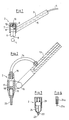
- Fig. 1 Grundaufbau einer Haltevorrichtung nach der Erfindung in Form einer Saugpipette,
- Fig. 2 den Grundaufbau einer praktischen Realisierungsmöglichkeit,
- Fig. 3 den Einsatz eines Adhäsionspfropfens in Verbindung mit einem Haltekopf und
- Fig. 4 eine Ausführungsmöglichkeit für eine Haltevorrichtung zur Übernahme von Bauteilen, die durch Anpicksen gehalten werden können.
- 1 basic structure of a holding device according to the invention in the form of a suction pipette,
- 2 shows the basic structure of a practical implementation possibility,
- Fig. 3 shows the use of an adhesion plug in connection with a holding head and
- Fig. 4 shows an embodiment of a holding device for taking over components that can be held by pecking.
Anhand der Fig. 1 wird zunächst die Erfindung nochmals im Zusammenhang erläutert. Dabei wird davon ausgegangen, daß ein zylinderförmiges SMD-Schaltelement 1 beim Annähern einer aus einem Haltekopf 2 mit Haltestiel 3 bestehenden Haltevorrichtung durch Unterdruck angesaugt werden soll. Dabei ist der Haltekopf 2 in seinem vorderen Bereich dem Bauelement 1 insoweit angepaßt, daß der über die Zuleitung 4 und Innenführung 5 im Stiel 3 von einem Unterdruckerzeuger aufgebaute Unterdruck voll abgedichtet wird und dadurch das Bauelement 1 hält.1, the invention is first explained again in context. It is assumed that a cylindrical SMD switching element 1 should be sucked in by negative pressure when a holding device consisting of a
Entsprechend dem Vorschlag nach der Erfindung ist der Haltekopf zweiteilig ausgeführt, wobei der vordere Gleitteil 6 mit der Ansaugöffnung 8 gegen Druck einer Feder 10 nach innen geschoben werden kann. Hierzu ist das mit dem Stiel 3 festverbundene starre Teil 7 als Führung ausgebildet.According to the proposal according to the invention, the holding head is made in two parts, the
Im Inneren des Haltekopfes ist ein Kugelventil 9 angedeutet, das über eine mechanische Wippe 11 zwei verschiedene Stellungen einnehmen kann, wobei in der gezeichneten Lage der Unterdruck unterbunden sein soll, während bei einem Umschnappen nach links die Kugel die Saugöffnung freigeben würde. Um diese Schnappwippe 11 hin- und herzusteuern sind zwei Steuerstifte 12 vorgesehen, die das Umschalten der Schnappwippe immer dann auslösen, wenn das Vorderteil kurz nach hinten gedrückt wird.In the interior of the holding head, a
In dem dargestellten Fall wäre nun in der Leitung 5 im Haltestiel 3 Unterdruck vorhanden und die Ventilkugel 9 in der dargestellten Lage, so daß an der Saugöffnung 8 keinerlei Sauggeräusch zu hören ist und auch keine Luft angesaugt wird.In the case shown, vacuum would now be present in line 5 in the
Wird die gesamte Vorrichtung auf das Bauelement 1 gebracht und dort ein gewisser Druck ausgeübt, was unmittelbar möglich ist, da das Bauelement ja in einem Behälter entweder am Boden oder auf anderen Bauelementen liegt, dann wird der Kopf 6 nach innen gedrückt und der rechte der Steuerstift 12 würde die Schaltwippe 11 nach links drücken, wo sie stabil stehen bleibt, auch wenn der Kopf wieder aufgrund der Gegenkraft der Feder 10 nach unten gedrückt wird. Die Kugel 9 gibt den Saugweg frei und der Unterdruck entsteht an der Ansaugöffnung 8.If the entire device is brought onto the component 1 and a certain pressure is exerted there, which is immediately possible, since the component is in a container either on the floor or on other components, then the
Die Haltevorrichtung kann dann mit dem Bauelement 1 beliebig bewegt werden und, wenn die Bedienungsperson dann das Bauelement 1 auf einer Leiterplatte (nicht gezeigt) absetzt und kurz einen Druck ausübt, der für das einwandfreie Auflegen des Bauelementes auf der Leiterplatte sowieso notwendig ist, schaltet der linke Steuerstift die Schaltwippe 11 wieder um und die Saugöffnung ist verschlossen, so daß die gesamte Haltevorrichtung von dem Bauelement 1, da diese sich auf der Leiterplatte befindet und dort verlötet wird, unmittelbar abgehoben werden kann. Nun ist bis zum Aufsetzen der Haltevorrichtung auf das nächste Bauelement an der Saugöffnung keinerlei Unterdruck vorhanden.The holding device can then be moved as desired with the component 1 and, if the operator then places the component 1 on a printed circuit board (not shown) and briefly exerts a pressure which is necessary anyway for the component to be placed correctly on the printed circuit board, the switch the left control pin, the rocker switch 11 again and the suction opening is closed, so that the entire holding device can be lifted off the component 1, since it is on the circuit board and is soldered there. Now there is no negative pressure at all until the holding device is placed on the next component at the suction opening.
Das Prinzip der Erfindung wurde zunächst anhand der Fig. 1 bewußt sehr schematisch und ohne konstruktive Details erläutert, da es zur Realisierung der aufgezeigten Funktion eine Vielzahl von konstruktiven Maßnahmen gibt, die dem Fachmann geläufig sind. Es sei dabei nur an die Vielzahl der in Verbindung mit Kugelschreibern bekannten Umschaltvorrichtungen verwiesen, die auf einen Druck die Schreibspitze nach außen führen, dort stabil halten und auf den nächsten Druck den Stift wieder zurückschnappen lassen, ohne daß er wieder nach vorne fällt.The principle of the invention was first deliberately explained very schematically on the basis of FIG. 1 and without constructive details, since there are a large number of constructive measures which are known to the person skilled in the art to implement the function shown. It should only be referred to the multitude of switching devices known in connection with ballpoint pens, which lead the writing tip to the outside at one pressure, hold it there steadily and snap the pen back again at the next pressure without it falling again.
Die Fig. 2 zeigt in einer etwas detaillierten Form den Aufbau einer Haltevorichtung nach der Erfindung in Form einer Saugpipette. Bei der dargestellten Ausführungsform wird der Schlauch mit dem Unterdruck aus dem Handgriff 3 herausgeführt und von oben in den widerum zweiteiligen Haltekopf 2 geführt. Dabei ist der Schlauch 14 luftdicht drehbar im oberen Ansatz des Haltekopfes 2 geführt, um eine beliebige räumliche Zuordnung des Haltestieles 3 zum Haltekopf 2 zu ermöglichen. Hierzu ist einmal ein Schaniergelenk 16 vorgesehen, das die Einstellung eines beliebigen Winkels des Haltestieles 3 zur Achse des Haltekopfes 2 ermöglicht.Fig. 2 shows in a somewhat detailed form the structure of a holding device according to the invention in the form of a suction pipette. In the embodiment shown, the hose is led out of the
Diese Scharnier 16 ist an einer Hülse 17 befestigt. Die Hülse 17, deren Achse mit der Mittellinie des Haltekopfes 2 zusammenfällt, ist frei drehbar in dem Haltekopf 2 gelagert, so daß auch insoweit der Haltestiel um den Haltekopf 2 herumgedreht werden kann.This
Bei der dargestellten Ausführungsform ist die Saugrohrspitze 20 auswechselbar dargestellt. Das - nicht gezeigte - Umschaltglied wird bei der vorgesehenen Ausführungsform elektrisch gesteuert, und zwar über die elektrischen Kontakte 18 und 19, die durch eine nur angedeutete Feder auseinander gedrückt werden.In the illustrated embodiment, the
Es ist auch aus dieser Darstellung ersichtlich, daß durch einen geringen Druck auf die Saugspitze 20 des Kopfes 2 nach oben z.B. mit Hilfe des Haltestieles 13 sich die beiden Kontakte berühren und einen Stromkreis herstellen, der ein bistabiles Kippglied dann entsprechend umschaltet, das seinerseits wiederum das Ein- und Ausschalten des Unterdruckes auslöst.It can also be seen from this illustration that a slight pressure on the
Anhand der Fig. 3 wird im folgenden nur angedeutet, daß die Haltevorrichtung nach der Erfindung auch ohne Anschluß an eine Saugquelle realisiert werden kann. Dabei ist in der Fig. 3 lediglich der Haltekopf ohne Haltestiel schematisch angedeutet, der wiederum zweiteilig ausgeführt ist. Im Gegensatz zu den vorbeschriebenen Ausführungsformen ist an der Spitze des Haltekopfes ein Pfropfen aus einem adhäsiven Material, an welchem ein Bauelement mit ausreichender Kraft für einen Transport haften bleibt.3 is only hinted at in the following that the holding device according to the invention can also be realized without connection to a suction source. In this case, only the holding head without holding handle is indicated schematically in FIG. 3, which in turn is made in two parts. In contrast to the above-described embodiments, there is a plug made of an adhesive material at the tip of the holding head, to which a component with sufficient force remains for transport.
In diesem Fall ist ein mechanisch arbeitendes bistabiles Umschaltglied 21 vorgesehen, das - ähnlich wie bei einem Kugelschreiber - bei einem Druck die Abdrückstange 24 mit Spitze 23 zurückzieht oder beim nächsten Druck durch den Pfropfen 22 nach vorne schiebt.In this case, a mechanically operating
Wird eine Haltevorrichtung mit einem derartigen Kopf auf ein Bauelement aufgedrückt, schiebt sich die Spitze 23 in dem Pfropfen 22 zurück und bleibt dort abhängig von dem bistabilen Umschaltglied 21 in zurückgezogenem Zustand, so daß das Bauelement unmittelbar an dem adhäsiven Haltekopf 22 kleben bleibt. Beim Aufsetzen des dann transportierten Bauelementes auf eine Leiterplatte wird wiederum - wie schon erläutert - ein kurzer Druck ausgeübt, wodurch die Spitze 23 des Stiftes 24 nach vorne kommt und das Bauelement von der Klebeoberfläche wegdrückt.If a holding device with such a head is pressed onto a component, the
Bei der Erläuterung der Erfindung wurde immer davon ausgegangen, daß konkrete SMD-Schaltelemente, für die die Erfindung in besonderer Weise geeignet ist, aufgenommen, transportiert und abgelegt werden sollen. Das Prinzip der Erfindung ist auch bei anderen Kleinteilen, beispielsweise kleineren Zwischenlagen, Blättchen und dergleichen einsetzbar. Sofern Teile aufgenommen werden sollen, die beispielsweise aus Papier oder einem anderen weichen Stoff betsehen, dann kann anStelle eines adhäsiven Pfropfens auch einfach ein kleiner Pickser vorgesehen werden, der in einer Hülse geführt ist, wobei die Hülse abhängig von einem bistabilen Umschaltglied entweder über die Spitze vorgeschoben oder so zurückgezogen wird, daß mit der Spitze das Papierblättchen oder dergleichen aufgenommen werden kann. Dies ist anschaulich in Fig. 4 in einem Ausschnitt gezeigt, wo eine Spitze 23 a die dem Abstreifer in Fig. 3 entsprechen kann, in einer Hülse 24 a geführt ist, die dem Stab 24 entspricht und entweder nach vorne geschoben oder, wie dargestellt, zurückgezogen ist. Beim Vorschieben würde dann ein aufgenommenes Kleinelement abgestreift und könnte so abgestreift werden.When explaining the invention, it was always assumed that specific SMD switching elements for which the invention is particularly suitable should be picked up, transported and stored. The principle of the invention can also be used for other small parts, for example smaller intermediate layers, leaflets and the like. If parts are to be included that are made of paper or another soft material, for example, instead of an adhesive plug, a small picker can simply be provided, which is guided in a sleeve, the sleeve depending on a bistable switching element either over the tip is advanced or withdrawn so that the tip of the paper sheet or the like can be picked up. This is clearly shown in FIG. 4 in a section where a
Für den auf dem Sachgebiet tätigen Fachmann sind noch weitere Abwandlungen möglich, wobei in jedem Fall darauf zu achten ist, daß durch einen einfachen Druck auf die Haltespitze selbst, gleichgültig ob dort eine Saugöffnung oder eine andere Haftmöglichkeit vorhanden ist, ein bistabiles Umschaltglied jeweils umgeschaltet wird.Further modifications are possible for the person skilled in the art, in which case it must be ensured that a bistable switching element is switched over by simply pressing the holding tip itself, irrespective of whether there is a suction opening or another liability .
Claims (7)
Priority Applications (1)
| Application Number | Priority Date | Filing Date | Title |
|---|---|---|---|
| AT87105232T ATE47115T1 (en) | 1986-04-08 | 1987-04-08 | HOLDING DEVICE FOR TAKING, TRANSPORTING AND STORING SMALL COMPONENTS. |
Applications Claiming Priority (2)
| Application Number | Priority Date | Filing Date | Title |
|---|---|---|---|
| DE19863611789 DE3611789A1 (en) | 1986-04-08 | 1986-04-08 | HOLDING DEVICE FOR RECEIVING, TRANSPORTING AND DEPOSITING SMALL COMPONENTS |
| DE3611789 | 1986-04-08 |
Publications (3)
| Publication Number | Publication Date |
|---|---|
| EP0241024A2 true EP0241024A2 (en) | 1987-10-14 |
| EP0241024A3 EP0241024A3 (en) | 1988-07-20 |
| EP0241024B1 EP0241024B1 (en) | 1989-10-11 |
Family
ID=6298227
Family Applications (1)
| Application Number | Title | Priority Date | Filing Date |
|---|---|---|---|
| EP87105232A Expired EP0241024B1 (en) | 1986-04-08 | 1987-04-08 | Holder device for picking-up, transporting and depositing micro-components |
Country Status (4)
| Country | Link |
|---|---|
| US (1) | US4770454A (en) |
| EP (1) | EP0241024B1 (en) |
| AT (1) | ATE47115T1 (en) |
| DE (2) | DE3611789A1 (en) |
Cited By (5)
| Publication number | Priority date | Publication date | Assignee | Title |
|---|---|---|---|---|
| WO1989004547A1 (en) * | 1987-11-09 | 1989-05-18 | Miroslav Tresky | Hand tool for assembling small parts, in particular electronic components |
| FR2652334A1 (en) * | 1989-09-22 | 1991-03-29 | Recif Sa | NOZZLE FOR VACUUM PIPETTE BODY IN PARTICULAR. |
| FR2673164A1 (en) * | 1991-02-26 | 1992-08-28 | Giat Ind Sa | Device for dispensing components from a bulk store |
| GB2271338A (en) * | 1992-10-06 | 1994-04-13 | John Sanders | Hand held pick-up tool |
| GB2327062A (en) * | 1997-07-09 | 1999-01-13 | Hamilton Designs Limited | Suction operated seed handling device |
Families Citing this family (21)
| Publication number | Priority date | Publication date | Assignee | Title |
|---|---|---|---|---|
| DE4314999C2 (en) * | 1993-05-06 | 1995-05-18 | Fezer Maschf Albert | Vacuum lifting device |
| DE4430381C2 (en) * | 1993-08-31 | 1997-02-27 | Smc Kk | Suction pipette |
| US5414955A (en) * | 1994-08-03 | 1995-05-16 | Morin; Thomas M. | Hand held seeder |
| US6074609A (en) * | 1996-04-24 | 2000-06-13 | Glaxo Wellcome Inc. | Systems for arraying beads |
| US6151973A (en) * | 1999-01-29 | 2000-11-28 | Glaxo Wellcome Inc. | Bead picking apparatus and method |
| US6497155B1 (en) * | 1999-02-09 | 2002-12-24 | Pharmacopeia, Inc. | Article comprising a particle retrieval device |
| WO2000049382A2 (en) * | 1999-02-16 | 2000-08-24 | The Perkin-Elmer Corporation | Bead dispensing system |
| CN1263361C (en) * | 1999-11-09 | 2006-07-05 | 西门子公司 | Vacuum suction tube for absorbing electrical components |
| FR2804892B1 (en) * | 2000-02-11 | 2002-04-26 | Aerospatiale Matra Airbus | ADJUSTABLE GRIP MEMBER FOR THE TRANSPORT OR MACHINING OF ANY SHAPED PART |
| US6471917B1 (en) * | 2000-04-11 | 2002-10-29 | Affymax, Inc. | System and method for single or multiple bead distribution with an adjustable capillary |
| US6749238B2 (en) * | 2002-04-26 | 2004-06-15 | Delaware Capital Formation, Inc. | Vacuum nozzle |
| DE10327932A1 (en) * | 2003-06-20 | 2005-01-05 | Hauck Gmbh & Co Kg | Stroller with brake or locking device |
| US7767052B2 (en) * | 2006-12-18 | 2010-08-03 | The Goodyear Tire & Rubber Company | Method of assembling an electronic device into a tire |
| US7631912B2 (en) * | 2007-07-31 | 2009-12-15 | Evergreen Packaging Inc. | Lifting device for a vacuum transfer system |
| CN102131717A (en) * | 2008-06-23 | 2011-07-20 | D·拉普科 | Apparatus for picking up, holding and dispensing objects |
| US8403388B1 (en) * | 2011-07-20 | 2013-03-26 | Michael Wendt | Hybrid nozzle for pick and place assembly of very small form factor components |
| JP5851868B2 (en) * | 2012-02-03 | 2016-02-03 | 三菱重工業株式会社 | Bar-shaped member chucking device and bar-shaped member chucking method |
| CN104271322B (en) * | 2012-03-08 | 2016-09-21 | 品质制造有限公司 | Touch Sensitive Robotic Gripper |
| CN103692377A (en) * | 2013-11-29 | 2014-04-02 | 湖北港源电气有限公司 | Attraction-releasing device for thin small parts |
| JP6380160B2 (en) * | 2015-02-25 | 2018-08-29 | 三菱電機株式会社 | Vacuum tweezers and semiconductor device manufacturing method |
| DE102019127292B4 (en) * | 2019-10-10 | 2023-01-19 | Asm Assembly Systems Gmbh & Co. Kg | Device and method for precise assembly with assembly elements |
Family Cites Families (9)
| Publication number | Priority date | Publication date | Assignee | Title |
|---|---|---|---|---|
| GB925381A (en) * | 1958-07-12 | 1963-05-08 | Reiners Walter | Cop, bobbin or like wound textile package handling devices |
| US3095229A (en) * | 1959-05-01 | 1963-06-25 | Philips Corp | Device for handling articles |
| DE1756262C3 (en) * | 1968-04-26 | 1978-07-20 | Vacu-Lift Maschinenbaugesellschaft Mbh, 4407 Emsdetten | Vacuum hoist with a switching device operated by the piston rod |
| US3424486A (en) * | 1966-11-29 | 1969-01-28 | Clifton Corley | Contact lens handling apparatus |
| GB1243283A (en) * | 1969-01-08 | 1971-08-18 | Welwyn Electric Ltd | Improvements in or relating to handling devices |
| US4496180A (en) * | 1983-07-20 | 1985-01-29 | Cincinnati Milacron Industries, Inc. | Vacuum handling apparatus |
| US4657470A (en) * | 1984-11-15 | 1987-04-14 | Westinghouse Electric Corp. | Robotic end effector |
| DE8514640U1 (en) * | 1985-05-17 | 1985-09-19 | Royonic Elektronik-Produktionsmaschinen GmbH, 8057 Eching | Vacuum tweezers |
| US4674784A (en) * | 1986-02-24 | 1987-06-23 | Avondale Industries, Inc. | Suction-type gripping mechanism with magnetic actuated vent valve |
-
1986
- 1986-04-08 DE DE19863611789 patent/DE3611789A1/en not_active Withdrawn
-
1987
- 1987-04-07 US US07/035,500 patent/US4770454A/en not_active Expired - Fee Related
- 1987-04-08 EP EP87105232A patent/EP0241024B1/en not_active Expired
- 1987-04-08 DE DE8787105232T patent/DE3760732D1/en not_active Expired
- 1987-04-08 AT AT87105232T patent/ATE47115T1/en not_active IP Right Cessation
Cited By (7)
| Publication number | Priority date | Publication date | Assignee | Title |
|---|---|---|---|---|
| WO1989004547A1 (en) * | 1987-11-09 | 1989-05-18 | Miroslav Tresky | Hand tool for assembling small parts, in particular electronic components |
| FR2652334A1 (en) * | 1989-09-22 | 1991-03-29 | Recif Sa | NOZZLE FOR VACUUM PIPETTE BODY IN PARTICULAR. |
| WO1991004212A1 (en) * | 1989-09-22 | 1991-04-04 | Recif S.A. | Tip for a pipette barrel, especially a vacuum pipette barrel |
| FR2673164A1 (en) * | 1991-02-26 | 1992-08-28 | Giat Ind Sa | Device for dispensing components from a bulk store |
| GB2271338A (en) * | 1992-10-06 | 1994-04-13 | John Sanders | Hand held pick-up tool |
| GB2327062A (en) * | 1997-07-09 | 1999-01-13 | Hamilton Designs Limited | Suction operated seed handling device |
| GB2327062B (en) * | 1997-07-09 | 2001-10-17 | Hamilton Design Ltd T W | Handling particulate material |
Also Published As
| Publication number | Publication date |
|---|---|
| DE3611789A1 (en) | 1987-10-22 |
| US4770454A (en) | 1988-09-13 |
| ATE47115T1 (en) | 1989-10-15 |
| EP0241024B1 (en) | 1989-10-11 |
| DE3760732D1 (en) | 1989-11-16 |
| EP0241024A3 (en) | 1988-07-20 |
Similar Documents
| Publication | Publication Date | Title |
|---|---|---|
| EP0241024B1 (en) | Holder device for picking-up, transporting and depositing micro-components | |
| DE3620944C2 (en) | Device and method for equipping printed circuit boards with electronic components using guide bodies | |
| DE2944810C2 (en) | Mounting head for mounting electronic components | |
| DE2660368C2 (en) | Pick and place machine for inserting the leads of electronic components of the parallel line type into openings provided for this purpose in printed circuits | |
| EP1111391B1 (en) | Clamping device for holding and aligning an item such as a microtitration plate, and method for its use | |
| EP0268881A1 (en) | Device for testing and sorting electronic compounds such as IC's | |
| DE1524965A1 (en) | Recording and / or playback device | |
| DE1955193A1 (en) | Method and device for changing tools on a machine with reciprocating working movement | |
| EP0315161B1 (en) | Apparatus for mounting, especially on printed circuit boards | |
| EP0338454B1 (en) | Device for mounting and/or soldering or gluing electronic components on printed circuit boards | |
| DE3740594C2 (en) | ||
| DE3023449A1 (en) | DEVICE FOR TRANSPORTING SMALL PARTS | |
| DE69116095T2 (en) | Device for dispensing small objects | |
| DE8609523U1 (en) | Holding device for picking up, transporting and storing small components | |
| DE102007001722B4 (en) | Device for picking up, transporting and sorting electronic components | |
| DE29617668U1 (en) | Device for producing a suction surface on an object and electrical component formed thereby | |
| DE102021124498B3 (en) | Support pin for supporting a substrate in a placement area of a placement machine and placement machine with a magazine with a plurality of such support pins. | |
| DE10040095B4 (en) | Apparatus for equipping printed circuit boards | |
| DE1943393C3 (en) | Device for loosening, in particular, four-pole electrical components from their carrier plate | |
| DE1258935B (en) | Equipping device for equipping carrier plates with electrical components of telecommunications technology | |
| DE10035962B4 (en) | Apparatus and method for picking up and delivering substrates | |
| DE19717361C2 (en) | Pipetting device | |
| DE10111471B4 (en) | Apparatus and method for picking up and delivering substrates | |
| DE1069724B (en) | ||
| DD247566A1 (en) | DEVICE FOR RECEIVING AND DISTRIBUTING A DIP COMPONENT |
Legal Events
| Date | Code | Title | Description |
|---|---|---|---|
| PUAI | Public reference made under article 153(3) epc to a published international application that has entered the european phase |
Free format text: ORIGINAL CODE: 0009012 |
|
| AK | Designated contracting states |
Kind code of ref document: A2 Designated state(s): AT BE CH DE ES FR GB GR IT LI LU NL SE |
|
| PUAL | Search report despatched |
Free format text: ORIGINAL CODE: 0009013 |
|
| AK | Designated contracting states |
Kind code of ref document: A3 Designated state(s): AT BE CH DE ES FR GB GR IT LI LU NL SE |
|
| 17P | Request for examination filed |
Effective date: 19880621 |
|
| 17Q | First examination report despatched |
Effective date: 19881017 |
|
| GRAA | (expected) grant |
Free format text: ORIGINAL CODE: 0009210 |
|
| AK | Designated contracting states |
Kind code of ref document: B1 Designated state(s): AT BE CH DE ES FR GB GR IT LI LU NL SE |
|
| PG25 | Lapsed in a contracting state [announced via postgrant information from national office to epo] |
Ref country code: IT Free format text: LAPSE BECAUSE OF FAILURE TO SUBMIT A TRANSLATION OF THE DESCRIPTION OR TO PAY THE FEE WITHIN THE PRE;WARNING: LAPSES OF ITALIAN PATENTS WITH EFFECTIVE DATE BEFORE 2007 MAY HAVE OCCURRED AT ANY TIME BEFORE 2007. THE CORRECT EFFECTIVE DATE MAY BE DIFFERENT FROM THE ONE RECORDED.SCRIBED TIME-LIMIT Effective date: 19891011 Ref country code: NL Effective date: 19891011 Ref country code: SE Effective date: 19891011 Ref country code: FR Free format text: THE PATENT HAS BEEN ANNULLED BY A DECISION OF A NATIONAL AUTHORITY Effective date: 19891011 Ref country code: GR Free format text: LAPSE BECAUSE OF FAILURE TO SUBMIT A TRANSLATION OF THE DESCRIPTION OR TO PAY THE FEE WITHIN THE PRESCRIBED TIME-LIMIT Effective date: 19891011 Ref country code: GB Effective date: 19891011 Ref country code: BE Effective date: 19891011 |
|
| REF | Corresponds to: |
Ref document number: 47115 Country of ref document: AT Date of ref document: 19891015 Kind code of ref document: T |
|
| REF | Corresponds to: |
Ref document number: 3760732 Country of ref document: DE Date of ref document: 19891116 |
|
| PG25 | Lapsed in a contracting state [announced via postgrant information from national office to epo] |
Ref country code: ES Free format text: LAPSE BECAUSE OF FAILURE TO SUBMIT A TRANSLATION OF THE DESCRIPTION OR TO PAY THE FEE WITHIN THE PRESCRIBED TIME-LIMIT Effective date: 19900122 |
|
| EN | Fr: translation not filed | ||
| NLV1 | Nl: lapsed or annulled due to failure to fulfill the requirements of art. 29p and 29m of the patents act | ||
| PG25 | Lapsed in a contracting state [announced via postgrant information from national office to epo] |
Ref country code: AT Effective date: 19900408 |
|
| GBV | Gb: ep patent (uk) treated as always having been void in accordance with gb section 77(7)/1977 [no translation filed] | ||
| PG25 | Lapsed in a contracting state [announced via postgrant information from national office to epo] |
Ref country code: LI Effective date: 19900430 Ref country code: CH Effective date: 19900430 Ref country code: LU Free format text: LAPSE BECAUSE OF NON-PAYMENT OF DUE FEES Effective date: 19900430 |
|
| PLBE | No opposition filed within time limit |
Free format text: ORIGINAL CODE: 0009261 |
|
| STAA | Information on the status of an ep patent application or granted ep patent |
Free format text: STATUS: NO OPPOSITION FILED WITHIN TIME LIMIT |
|
| 26N | No opposition filed | ||
| REG | Reference to a national code |
Ref country code: CH Ref legal event code: PL |
|
| PGFP | Annual fee paid to national office [announced via postgrant information from national office to epo] |
Ref country code: DE Payment date: 19910430 Year of fee payment: 5 |
|
| PG25 | Lapsed in a contracting state [announced via postgrant information from national office to epo] |
Ref country code: DE Effective date: 19930101 |