EP0240634A2 - Modul-Mehrfachkoppler für aneinandergrenzende Frequenzkanäle - Google Patents
Modul-Mehrfachkoppler für aneinandergrenzende Frequenzkanäle Download PDFInfo
- Publication number
- EP0240634A2 EP0240634A2 EP86304375A EP86304375A EP0240634A2 EP 0240634 A2 EP0240634 A2 EP 0240634A2 EP 86304375 A EP86304375 A EP 86304375A EP 86304375 A EP86304375 A EP 86304375A EP 0240634 A2 EP0240634 A2 EP 0240634A2
- Authority
- EP
- European Patent Office
- Prior art keywords
- channel
- multiplexer
- filters
- channels
- module
- Prior art date
- Legal status (The legal status is an assumption and is not a legal conclusion. Google has not performed a legal analysis and makes no representation as to the accuracy of the status listed.)
- Withdrawn
Links
Images


Classifications
-
- H—ELECTRICITY
- H04—ELECTRIC COMMUNICATION TECHNIQUE
- H04J—MULTIPLEX COMMUNICATION
- H04J1/00—Frequency-division multiplex systems
- H04J1/02—Details
- H04J1/12—Arrangements for reducing cross-talk between channels
Definitions
- This invention relates to a microwave frequency channel combining apparatus, commonly referred to as a multiplexer and to a method of constructing such a multiplexer.
- this invention relates to a modular contiguous channel multiplexer that provides complete flexibility in that any number of channels can be contiguously combined in any preferred order of relative frequencies and any number of channels can be added at any future time without affecting the performance of the existing channels in the multiplexer.
- any number of channels can be removed from an upstream position in a multiplexer relative to the remaining channels without affecting the performance of other channels in the multiplexer.
- each channel is a separate module which is able to be added or removed from the main chain without affecting the existing or remaining multiplexer.
- a multiplexer has an arrangement of contiguous channels relative to their operating frequencies, the guide bands between adjacent channels are insufficient or non-existent and strong interchannel interactions result.
- it is common to construct two non-contiguous multiplexers adjacent to one another and to combine them using a 3 dB hybrid. Even though this arrangement results in a power loss of approximately fifty percent and has other requirements that make it extremely expensive to construct and to operate, these types of multiplexers are still widely used in ground stations on a worldwide basis.
- This reason for this widespread use is that this type of multiplexer allows total flexibility in adding channels at any time without any sacrifice in the performance of other channels.
- channel asymmetry can reduce data rate and consequently can reduce revenue.
- channels cannot be added to or removed from existing multiplexer as asymmetries would then be introduced into the performance of adjacent channels, hence reducing their revenue earning capacity.
- the multiplexer described in the Bell patent does overcome the problem of the fifty percent power loss and the disadvantages generally apply only to the use of the multiplexer in a ground station.
- multiplexers used in spacecraft With multiplexers used in spacecraft, the fact that channels cannot be added or removed from the multiplexer without redesigning the entire multiplexer, is not a serious limitation as changes cannot be made in the design once the spacecraft is launched in any event. Also, when a multiplexer is designed for use in a spacecraft, the number and relative frequencies of channels is known and there is no difficulty in designing the multiplexer so that the channels are arranged in either ascending or descending order of frequency.
- a ground station owner may start with only two or three channels, for example, channels 1, 2 and 5. Subsequently, the ground station operator might be assigned a new channel, for example, channel 4, where consecutive channel numbers represent the operating frequency of each channel.
- channel 4 cannot be added to the arrangement of channels 1, 2 and 5 without redesigning and reconstructing the entire multiplexer. Of course, it may be necessary to add or remove additional channels on more than one occasion. If the multiplexer must be entirely redesigned each time, the cost of adding or removing channels to existing multiplexers can be prohibitive.
- Multiplexers used in ground stations are sometimes referred to as combiners. Ground stations usually do not have all of the channels that a satellite has but only a few non-consecutive channels.
- a contiguous channel multiplexer has at least two channels that are contiguously multiplexed relative to their operating frequency.
- the multiplexer has an upstream end and a downstream end.
- Each channel has a module with two substantially identical filters.
- At least one module, that is contiguous with a downstream module has filters that produce an asymmetrical filter function.
- the asymmetrical filter function combines with responses of other modules so that the multiplexer produces an overall symmetrical response.
- a method of constructing a contiguous channel multiplexer uses a multiplexer having at least two channels that are contiguously multiplexed relative to their operating frequency. Each channel has a module with two substantially identical filters. The method comprises choosing the filters of at least one module, that is contiguous with a downstream module, so that said filters produce an asymmetrical filter function and operating said multiplexer in such a way as to produce an overall symmetrical response.
- FIG. 5 there is shown a directional channel separation filter module 1.
- the module 1 is a basic building block of any hybrid coupled multiplexer and was suggested in the article by S. B. Cohn, et al., referred to above.
- Each filter module 1 consists of two quadrature hybrid couplers 11, 12, and two substantially identical bandpass filters f and f ⁇ .
- Such an arrangement has the following operational characteristics. If a signal enters port a, such that the signal is within the passband of filter f and f ⁇ , the signal will emerge from port d. If an out-of-band signal enters port c, the signal will be reflected off the filter f, f ⁇ and will emerge from port d.
- FIG. 1 there is shown a block diagram of a conventional contiguous channel multiplexer of the type suggested by S. B. Cohn, et al. in the paper referred to above.
- a multiplexer assembly 3 has filter modules, 31, 33, ... 32n-1 that are cascaded together in an odd channel non-contiguous multiplexing sequence and filter modules 32, 34, ... 32n, that are cascaded together in an even channel non-contiguous multiplexing sequence.
- this arrangement combines two separate non-contiguous multiplexers, one multiplexer having channels 1, 3, ... 2n-1 and the other multiplexer having channels 2, 4, ... 2n. If channels 1 and 2 or channels 3 and 4, etc.
- FIG 2 there is shown a prior art contiguous channel multiplexer, as proposed by R. Levy et al. in U.S. Patent #4,258,435, that can combine any number of contiguous channels while avoiding the loss of fifty percent of the output power of the multiplexer assembly 3 of Figure 1.
- filters, 63, 64, 65 and 66 are all connected to a common manifold 69 such that the signal at the output port of all 4 channels is combined into one composite signal.
- this type of multiplexer is optimal in terms of electrical performance and mechanical lightness and compactness, it suffers from a disadvantage in that it is not modular.
- FIG 3 there is shown a prior art contiguous channel multiplexer 26, as suggested by C. Bell et al. in U.S. Patent #4,029,902, using a series of directional channel separating filter modules 1.
- filter modules 21, 22, 23, ... 2n are cascaded to form a multiplexer assembly.
- the contiguously combined signal will emerge from port d of filter module 2n.
- termination R Similar to the multiplexer assembly 3 of Figure 1, all unused ports are terminated by termination R.
- the characteristics of this type of multiplexer are as follows. All channels are required to be cascaded in order of ascending or descending frequency, as illustrated in the multiplexer assembly 2 block diagram.
- curves 53, 54, 55 and 56 all have quite different shape and all exhibit asymmetrical behaviour even though the filters of all modules are substantially identical to one another. Such asymmetry is undesirable for modern digital communication traffic which dominates today's telecommunications industry. This is the end of the description of the prior art multiplexers.
- the filter function used in filter module 1 for filters f and f ⁇ will be one of four different types.
- the use of each type of filter function will be determined by the multiplexing sequence and conditions.
- the reasons for choosing four different kinds of filter function is to provide complete band-edge performance compensation for all frequency multiplexing orders such that symmetrical channel characteristics will result regardless of multiplexing order.
- the amplitude characteristics of the four different types of filter function are illustrated in Figures 6a through 6d. Curve 71 of Figure 6a represents a symmetrical elliptic/quasi-elliptic function response.
- Curve 72 of Figure 6b represents an asymmetric elliptic/quasi-elliptic function response that has one transmission zero which is placed at the positive jw-axis.
- Curve 73 of Figure 6c represents an asymmetric elliptic/quasi-elliptic function response that one transmission zero is being placed at the negative jw-axis.
- curve 74 of Figure 6d represents a Chebyshev function response with no transmission zeros.
- FIG. 7 is a block diagram showing a contiguous channel multiplexer 46 having a multiplexing sequence that will utilize all four kinds of filter module shown in Figures 6a to 6d, inclusive in order to achieve an overall symmetrical response for the multiplexer 46.
- said multiplexer 46 five filter modules 45, 43, 41, 44 and 42 are cascaded together in the illustrated order with respect to channel numbers 5, 3, 1, 4, 2 respectively.
- the objective of the multiplexer is to combine all five signals and have the combined signal emerge at port d of module 42 such that all channels exhibit an overall symmetric electrical passband characteristic.
- all unused ports are determined by a termination R.
- a channel is said to have a downstream channel, if port d of that channel filter module is connected to port c of another channel filter module.
- all channels in multiplexer 46 have a downstream channel except channel 2.
- all channels will have a downstream channel except the channel that is last in the cascaded chain.
- a multiplexer is designed so that the downstream end is the end nearest to an antenna for the multiplexer. In this way, channels can be added or removed from an upstream end of the multiplexer without disturbing the connection of the multiplexer to the antenna and the remaining parts of the multiplexer can continue to function.
- it would be possible to design a multiplexer so that the downstream end or the end opposite to the end where the antenna is connected. Based on the above definition of a downstream channel, the type of filter function to be selected for each channel by a given order of multiplexing frequency can be determined as follows:
- Concerning module type 0 where there are no contiguous downstream channels on both upper and lower bands of said channel, a module having a symmetric filter function with more than one pair of transmission zeros or no transmission zeros whatsoever could be used in place of the module having a symmetric filter function with one pair of transmission zeros.
- Concerning module type 1 where there is one contiguous downstream channel on the lower band of the said channel, a module having an asymmetric filter function with one more transmission zero on the positive jw-axis than on the negative jw-axis can generally be used in substitution for a module having an asymmetric filter function with one transmission zero on the positive jw-axis.
- a module having an asymmetric filter function with one more transmission zero in the negative jw-axis than on the positive jw-axis can generally be used in substitution for a module having an asymmetric filter function with one transmission zero on the negative jw-axis.
- Concerning module type 3 where there are two contiguous downstream channels on both the upper and lower bands of said channel, any module having a symmetrical filter function or a symmetrical filter function with one or more pairs of transmission zeros of a symmetrical filter function with no transmission zeros can generally be used in substitution for a module having a pure Chebyshev filter function with no transmission zeros. Numerous other variations will be readily apparent to those skilled in the art.
- module types 0, 1, 2, 3 can be redefined as a mathematical formula as follows:
- T i 2F(i,i+1) + F(i,i-1).
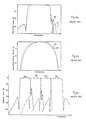
- Figures 8a through 8g illustrate the comparison of the ideal channel characteristic vs. filter module electrical characteristic before and after multiplexing.
- curves 61 and 62 are the ideal channel responses.
- Curves 81, 82, 83, 84, 85, 86, 87, 88 are the filter module characteristics before cascade in the sequence depicted in multiplexer 46 block diagram.
- Curves 71, 72, 73, 74, 75, 76, 77, 78 are the channel responses after all filter modules are cascaded according to the block diagram of multiplexer 46.
- curves 75, 76 are much closer to ideal curves 61, 62 than curves 85, 86.
- Figures 8g and 8h the amplitude and group delay characteristics respectively of a channel module type 3 are shown. Again, it can readily be seen that curves 77, 78 are much closer to ideal curves 61, 62 respectively than curves 87, 88. In other words, the overall symmetric channel characteristic is greatly enhanced and is very close to the ideal response by cascading filter modules in accordance with the present invention.
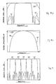
- FIG 9 the overall performance characteristics of the contiguous channel multiplexer 46 described in Figure 7 is shown.
- Channels 2, 4, 1, 3, 5 have loss response curves 63, 64, 65, 66, 67 respectively.
- Figure 9 the overall response of the multiplexer 46 is relatively perfectly symmetrical whereas the response of the multiplexer 26 shown in Figure 4c is not symmetrical and contains numerous distortions.
- the multiplexer of the present invention it is possible to use symmetric and asymmetric filter modules in combination in order to multiplex contiguous channels without any appreciable distortion.
- the multiplexer of the present invention utilizes filters that produce an asymmetrical filter function, yet the multiplexer can be operated in such a way as to produce an overall symmetric response.
- an advantage of the multiplexer of the present invention is that any reasonable number of channels can be arranged in random order with respect to frequency. Also, an additional channel or channels of any preferred frequency can be added at any time to an existing multiplexer so long as the additional channel or channels are inserted into the multiplexer in an upstream position relative to the existing channels, without being concerned with the frequency of the channel being added relative to the frequency of the existing channels and without disturbing the performance of the existing channels. Similarly, any existing channel is located upstream of all other channels can be removed from the multiplexer at any time without disturbing the performance of the remaining channels of the existing multiplexer.
- each filter of the multiplexer of the present invention has an input port and an output port, the inputs of the two filters in each module being interconnected by quadrative hybrid couplers and the output ports of the two filters in each module being interconnected by quadrative hybrid couplers.
- the modules contain appropriate impedences, for example, all unused ports are determined by a termination R.
- the multiplexer has at least two channels that are contiguously multiplexed relative to their operating frequency and each channel has a module with two substantially identical filters.
- the method involves choosing the filters of at least one module, that is contiguous with a downstream module, so that said filters produce an asymmetrical filter function and operate in said multiplexer in such a way as to produce an overall symmetrical response.
- each filter has an input port and an output port, the input ports of the two filters in each module being interconnected by quadrative hybrid couplers and the output ports of the filters of each module being interconnected by quadrative hybrid couplers.
- the method involves choosing the downstream channel first, then choosing sequentially the channel immediately upstream of the channel last chosen, and choosing the substantially identical filters of each module and sequence so that:
- a method for adding a new channel or channels involves adding any channels of any preferred frequency to the multiplexer by inserting said additional channels in an upstream position relative to the existing channels of said multiplexer.
- a method for removing a channel or channels from the multiplexer involves removing any channel or channels that are in an upstream position relative to the remaining channels of said multiplexer.
- channels are chosen in accordance with the method of the present invention and utilize the formula set out in the description. As one becomes more acquainted with the present invention, it will be discovered that it is not necessary to actually use the formula but to simply apply the design criterion for each module type as set out in the disclosure.
- the multiplexer could initially have been constructed with only channels 2 and 3. Then, channel 1 could have been added subsequently and channel 4 later yet. Similarly, by reversing the procedure, channel 4 could be removed from the multiplexer without affecting the performance of the remaining channels. Channel 1 could be removed at the same time as channel 4 or removed at a subsequent time.
- a ground station operator could have initially constructed channels 1 and 2 in accordance with the present invention. Later on, channels 4, 3 and 5 could be added simultaneously or one after another, each in an upstream position. Similarly, these channels could be removed together or one at a time by removing channel 5 first, channel 3 second and channel 4 third.
- a ground station operator could originally have constructed channels 1, 2, 4 with channel 4 being downstream and channel 1 being upstream. Subsequently, channels 3 and 5 could be added in the upstream position. Also, as previously discussed, channels 5 and 3 and even channel 1 could be removed simultaneously or sequentially as long as the channels being removed are in an upstream position relative to the remaining channels.
- the multiplexer could originally have been constructed in accordance with the present invention with channels 2, 3 and 4. Later on, channel 5 could have been added, followed by channels 1, 7 and 6, in that order. As with the other examples, any number of channels could also be removed as long as the channels removed are in an upstream position relative to the remaining channels.
- the importance of initially designing a multiplexer in accordance with the present invention can readily be seen as it is possible to add virtually any number of channels in any random order as long as each channel being added is added in an upstream position relative to the existing channels.
- any channels can be removed at any time as long as the channels removed are in an upstream position relative to the remaining channels.
- the response characteristics of the present invention are an improvement over those achieved by some of the prior art multiplexers. While examples have been given of particular arrangements of channels, the description is not intended to be restricted in any way and virtually any arrangement of any reasonable number of channels could be utilized.
Landscapes
- Engineering & Computer Science (AREA)
- Computer Networks & Wireless Communication (AREA)
- Signal Processing (AREA)
- Time-Division Multiplex Systems (AREA)
- Control Of Motors That Do Not Use Commutators (AREA)
Applications Claiming Priority (2)
| Application Number | Priority Date | Filing Date | Title |
|---|---|---|---|
| CA506262 | 1986-04-09 | ||
| CA000506262A CA1281821C (en) | 1986-04-09 | 1986-04-09 | Modular contiguous channel multiplexer |
Publications (2)
| Publication Number | Publication Date |
|---|---|
| EP0240634A2 true EP0240634A2 (de) | 1987-10-14 |
| EP0240634A3 EP0240634A3 (de) | 1989-06-14 |
Family
ID=4132850
Family Applications (1)
| Application Number | Title | Priority Date | Filing Date |
|---|---|---|---|
| EP86304375A Withdrawn EP0240634A3 (de) | 1986-04-09 | 1986-06-09 | Modul-Mehrfachkoppler für aneinandergrenzende Frequenzkanäle |
Country Status (4)
| Country | Link |
|---|---|
| US (1) | US4815075A (de) |
| EP (1) | EP0240634A3 (de) |
| JP (1) | JPS62239702A (de) |
| CA (1) | CA1281821C (de) |
Cited By (6)
| Publication number | Priority date | Publication date | Assignee | Title |
|---|---|---|---|---|
| EP0513696A3 (en) * | 1991-05-16 | 1993-04-28 | Siemens Aktiengesellschaft | Branching device |
| WO2004070869A1 (de) * | 2003-02-03 | 2004-08-19 | Tesat-Spacecom Gmbh & Co. Kg | Anordnung für eingangsmultiplexr |
| US7282963B2 (en) | 2003-04-04 | 2007-10-16 | Nec Corporation | Wide-band circuit coupled through a transmission line |
| EP2372831A1 (de) * | 2010-03-30 | 2011-10-05 | Astrium Limited | Ausgangsmultiplexer |
| FR2970816A1 (fr) * | 2011-01-24 | 2012-07-27 | St Microelectronics Sa | Combineur radiofrequence |
| US9231642B2 (en) | 2011-01-24 | 2016-01-05 | Stmicroelectronics Sa | Radio frequency splitter |
Families Citing this family (11)
| Publication number | Priority date | Publication date | Assignee | Title |
|---|---|---|---|---|
| EP0284442A3 (de) * | 1987-03-26 | 1989-09-27 | British Aerospace Public Limited Company | HF-Signalverteilung |
| FR2621130B1 (fr) * | 1987-09-25 | 1990-01-26 | Centre Nat Etd Spatiales | Dispositif de mesure de produits d'intermodulation d'un systeme recepteur |
| JPH0812964B2 (ja) * | 1990-07-25 | 1996-02-07 | 株式会社村田製作所 | 方向性フィルタおよびマルチプレクサ |
| US5233609A (en) * | 1990-08-27 | 1993-08-03 | Gte Government Systems | Multichannel multiplexer with frequency discrimination characteristics |
| US5327245A (en) * | 1992-02-11 | 1994-07-05 | Information Transmission Systems Corp. | Method and apparatus for combining adjacent channel television signals |
| US5438572A (en) * | 1993-01-29 | 1995-08-01 | The United States Of America As Represented By The Secretary Of The Navy | Microwave non-logarithmic periodic multiplexer with channels of varying fractional bandwidth |
| US6580729B1 (en) | 1999-11-29 | 2003-06-17 | General Signal Corporation | Signal multiplexer and method |
| US6710813B1 (en) | 2000-09-13 | 2004-03-23 | Spx Corporation | Multiplexer for adjacent NTSC and DTV channels |
| KR100438430B1 (ko) * | 2002-01-24 | 2004-07-03 | 삼성전자주식회사 | 이동통신시스템에서 트래픽 플로우 탬플릿 재정렬 장치 및방법 |
| GB2466028A (en) * | 2008-12-08 | 2010-06-09 | Univ Cardiff | High frequency measurement system |
| EP3646489A4 (de) * | 2017-06-27 | 2021-03-24 | Kaelus PTY Ltd | System und vorrichtung zur erkennung von fehlern bei einer funkfrequenzvorrichtung oder einem system |
Family Cites Families (4)
| Publication number | Priority date | Publication date | Assignee | Title |
|---|---|---|---|---|
| FR2218703B1 (de) * | 1973-02-16 | 1979-08-03 | Thomson Csf | |
| US4029902A (en) * | 1975-10-22 | 1977-06-14 | Hughes Aircraft Company | Contiguous channel multiplexer |
| US4240155A (en) * | 1978-06-28 | 1980-12-16 | Micro Communications, Inc. | Diplexer and multiplexer |
| US4258435A (en) * | 1979-01-08 | 1981-03-24 | Microwave Development Labs. Inc. | Manifold multiplexers |
-
1986
- 1986-04-09 CA CA000506262A patent/CA1281821C/en not_active Expired - Fee Related
- 1986-06-09 EP EP86304375A patent/EP0240634A3/de not_active Withdrawn
- 1986-11-07 JP JP61265426A patent/JPS62239702A/ja active Pending
-
1987
- 1987-03-04 US US07/021,908 patent/US4815075A/en not_active Expired - Fee Related
Cited By (9)
| Publication number | Priority date | Publication date | Assignee | Title |
|---|---|---|---|---|
| EP0513696A3 (en) * | 1991-05-16 | 1993-04-28 | Siemens Aktiengesellschaft | Branching device |
| WO2004070869A1 (de) * | 2003-02-03 | 2004-08-19 | Tesat-Spacecom Gmbh & Co. Kg | Anordnung für eingangsmultiplexr |
| US7282963B2 (en) | 2003-04-04 | 2007-10-16 | Nec Corporation | Wide-band circuit coupled through a transmission line |
| EP2372831A1 (de) * | 2010-03-30 | 2011-10-05 | Astrium Limited | Ausgangsmultiplexer |
| WO2011120986A1 (en) * | 2010-03-30 | 2011-10-06 | Astrium Limited | Output multiplexer |
| FR2970816A1 (fr) * | 2011-01-24 | 2012-07-27 | St Microelectronics Sa | Combineur radiofrequence |
| US8843087B2 (en) | 2011-01-24 | 2014-09-23 | Stmicroelectronics Sa | Radio frequency combiner |
| US9231642B2 (en) | 2011-01-24 | 2016-01-05 | Stmicroelectronics Sa | Radio frequency splitter |
| US9853345B2 (en) | 2011-01-24 | 2017-12-26 | Stmicroelectronics Sa | Radio frequency splitter |
Also Published As
| Publication number | Publication date |
|---|---|
| US4815075A (en) | 1989-03-21 |
| EP0240634A3 (de) | 1989-06-14 |
| JPS62239702A (ja) | 1987-10-20 |
| CA1281821C (en) | 1991-03-19 |
Similar Documents
| Publication | Publication Date | Title |
|---|---|---|
| US4815075A (en) | Modular contiguous channel multiplexer | |
| CA1078534A (en) | Contiguous channel multiplexer | |
| CA1063184A (en) | Non-recursive digital filter employing simple coefficients | |
| US20030002102A1 (en) | Device for frequency band demultiplexing | |
| JP3266430B2 (ja) | 光学パスバンドフィルタ | |
| US6429974B1 (en) | Add-drop multiplexer | |
| US7024116B2 (en) | Optical add drop multiplexer | |
| US6243179B1 (en) | Banded add drop device | |
| US6624723B2 (en) | Multi-channel frequency multiplexer with small dimension | |
| US3727152A (en) | Signal combiner or divider for differing frequencies | |
| US6546166B1 (en) | Multi-stage optical DWDM channel group interleaver | |
| US20020041727A1 (en) | Switch for optical signals | |
| CA1174384A (en) | Digital transmultiplexer | |
| US6002504A (en) | Device for the frequency transposition of optical signals | |
| EP1780828B1 (de) | Frequenzdiplexer mit einem Eingang und erstem und zweitem Ausgang. | |
| US6901184B2 (en) | Frequency comb for an optical WDM network | |
| US3426292A (en) | Phase-coherent band-splitting and recombination network | |
| US2374567A (en) | Multichannel carrier transmission system | |
| EP0986201A2 (de) | Breitbandiger aneinandergrenzender Multiplexer mit aneinandergrenzendem Diplexer | |
| US3859469A (en) | Combination hybrid and frequency division multiplexing circuit | |
| EP0793290B1 (de) | Modul-Mehrfachkoppler mit aneinandergrenzenden Ausgangssignalen | |
| CN1351786A (zh) | 相加-下降-多路器装置和光波波长路器-传输系统 | |
| US6768843B1 (en) | Cascaded fourier filter interleaver having enhanced performance | |
| US5030934A (en) | Crystal notch filter comprising discrete quartz crystals coupled to a trimmable RC bridging network | |
| US20080212966A1 (en) | Optimised Multiplexer/Demultiplexer Optical Structure |
Legal Events
| Date | Code | Title | Description |
|---|---|---|---|
| PUAI | Public reference made under article 153(3) epc to a published international application that has entered the european phase |
Free format text: ORIGINAL CODE: 0009012 |
|
| AK | Designated contracting states |
Kind code of ref document: A2 Designated state(s): DE FR GB IT SE |
|
| PUAL | Search report despatched |
Free format text: ORIGINAL CODE: 0009013 |
|
| AK | Designated contracting states |
Kind code of ref document: A3 Designated state(s): DE FR GB IT SE |
|
| 17P | Request for examination filed |
Effective date: 19891201 |
|
| 17Q | First examination report despatched |
Effective date: 19911014 |
|
| STAA | Information on the status of an ep patent application or granted ep patent |
Free format text: STATUS: THE APPLICATION IS DEEMED TO BE WITHDRAWN |
|
| 18D | Application deemed to be withdrawn |
Effective date: 19930323 |
|
| RIN1 | Information on inventor provided before grant (corrected) |
Inventor name: CAMERON, RICHARD J. |