EP0240500B1 - Trenneinheit - Google Patents
Trenneinheit Download PDFInfo
- Publication number
- EP0240500B1 EP0240500B1 EP19860900357 EP86900357A EP0240500B1 EP 0240500 B1 EP0240500 B1 EP 0240500B1 EP 19860900357 EP19860900357 EP 19860900357 EP 86900357 A EP86900357 A EP 86900357A EP 0240500 B1 EP0240500 B1 EP 0240500B1
- Authority
- EP
- European Patent Office
- Prior art keywords
- assembly according
- separating means
- separating
- separator assembly
- separator
- Prior art date
- Legal status (The legal status is an assumption and is not a legal conclusion. Google has not performed a legal analysis and makes no representation as to the accuracy of the status listed.)
- Expired
Links
- 239000013618 particulate matter Substances 0.000 claims abstract description 8
- 230000033001 locomotion Effects 0.000 claims description 24
- 230000009977 dual effect Effects 0.000 description 8
- 239000002245 particle Substances 0.000 description 7
- 230000000712 assembly Effects 0.000 description 5
- 238000000429 assembly Methods 0.000 description 5
- 239000000463 material Substances 0.000 description 5
- 150000003839 salts Chemical class 0.000 description 4
- 238000007789 sealing Methods 0.000 description 4
- 230000008859 change Effects 0.000 description 2
- 239000004033 plastic Substances 0.000 description 2
- 229920003023 plastic Polymers 0.000 description 2
- 244000043261 Hevea brasiliensis Species 0.000 description 1
- 241000206607 Porphyra umbilicalis Species 0.000 description 1
- 230000008901 benefit Effects 0.000 description 1
- 230000015572 biosynthetic process Effects 0.000 description 1
- 230000000903 blocking effect Effects 0.000 description 1
- 238000010276 construction Methods 0.000 description 1
- 230000002844 continuous effect Effects 0.000 description 1
- 230000007797 corrosion Effects 0.000 description 1
- 238000005260 corrosion Methods 0.000 description 1
- 239000013078 crystal Substances 0.000 description 1
- 230000000694 effects Effects 0.000 description 1
- 239000012530 fluid Substances 0.000 description 1
- 230000008014 freezing Effects 0.000 description 1
- 238000007710 freezing Methods 0.000 description 1
- 230000014759 maintenance of location Effects 0.000 description 1
- 230000007246 mechanism Effects 0.000 description 1
- 239000002184 metal Substances 0.000 description 1
- 229920003052 natural elastomer Polymers 0.000 description 1
- 229920001194 natural rubber Polymers 0.000 description 1
- 230000002093 peripheral effect Effects 0.000 description 1
- 230000004044 response Effects 0.000 description 1
- 239000004576 sand Substances 0.000 description 1
- 229920002379 silicone rubber Polymers 0.000 description 1
- 239000004945 silicone rubber Substances 0.000 description 1
- 239000000126 substance Substances 0.000 description 1
- 229920003051 synthetic elastomer Polymers 0.000 description 1
- 239000005061 synthetic rubber Substances 0.000 description 1
- 239000003643 water by type Substances 0.000 description 1
Images






Classifications
-
- B—PERFORMING OPERATIONS; TRANSPORTING
- B01—PHYSICAL OR CHEMICAL PROCESSES OR APPARATUS IN GENERAL
- B01D—SEPARATION
- B01D46/00—Filters or filtering processes specially modified for separating dispersed particles from gases or vapours
- B01D46/10—Particle separators, e.g. dust precipitators, using filter plates, sheets or pads having plane surfaces
-
- B—PERFORMING OPERATIONS; TRANSPORTING
- B01—PHYSICAL OR CHEMICAL PROCESSES OR APPARATUS IN GENERAL
- B01D—SEPARATION
- B01D46/00—Filters or filtering processes specially modified for separating dispersed particles from gases or vapours
- B01D46/42—Auxiliary equipment or operation thereof
- B01D46/44—Auxiliary equipment or operation thereof controlling filtration
- B01D46/46—Auxiliary equipment or operation thereof controlling filtration automatic
-
- B—PERFORMING OPERATIONS; TRANSPORTING
- B01—PHYSICAL OR CHEMICAL PROCESSES OR APPARATUS IN GENERAL
- B01D—SEPARATION
- B01D53/00—Separation of gases or vapours; Recovering vapours of volatile solvents from gases; Chemical or biological purification of waste gases, e.g. engine exhaust gases, smoke, fumes, flue gases, aerosols
- B01D53/26—Drying gases or vapours
- B01D53/266—Drying gases or vapours by filtration
-
- F—MECHANICAL ENGINEERING; LIGHTING; HEATING; WEAPONS; BLASTING
- F02—COMBUSTION ENGINES; HOT-GAS OR COMBUSTION-PRODUCT ENGINE PLANTS
- F02C—GAS-TURBINE PLANTS; AIR INTAKES FOR JET-PROPULSION PLANTS; CONTROLLING FUEL SUPPLY IN AIR-BREATHING JET-PROPULSION PLANTS
- F02C7/00—Features, components parts, details or accessories, not provided for in, or of interest apart form groups F02C1/00 - F02C6/00; Air intakes for jet-propulsion plants
- F02C7/04—Air intakes for gas-turbine plants or jet-propulsion plants
- F02C7/05—Air intakes for gas-turbine plants or jet-propulsion plants having provisions for obviating the penetration of damaging objects or particles
- F02C7/052—Air intakes for gas-turbine plants or jet-propulsion plants having provisions for obviating the penetration of damaging objects or particles with dust-separation devices
-
- F—MECHANICAL ENGINEERING; LIGHTING; HEATING; WEAPONS; BLASTING
- F02—COMBUSTION ENGINES; HOT-GAS OR COMBUSTION-PRODUCT ENGINE PLANTS
- F02M—SUPPLYING COMBUSTION ENGINES IN GENERAL WITH COMBUSTIBLE MIXTURES OR CONSTITUENTS THEREOF
- F02M35/00—Combustion-air cleaners, air intakes, intake silencers, or induction systems specially adapted for, or arranged on, internal-combustion engines
- F02M35/02—Air cleaners
- F02M35/04—Air cleaners specially arranged with respect to engine, to intake system or specially adapted to vehicle; Mounting thereon ; Combinations with other devices
-
- B—PERFORMING OPERATIONS; TRANSPORTING
- B01—PHYSICAL OR CHEMICAL PROCESSES OR APPARATUS IN GENERAL
- B01D—SEPARATION
- B01D2273/00—Operation of filters specially adapted for separating dispersed particles from gases or vapours
- B01D2273/14—Filters which are moved between two or more positions, e.g. by turning, pushing
Definitions
- the present invention relates to a separator assembly for removing particulate matter entrained in air passing through an air duct, wherein the duct is arranged to allow air flow in a first direction creating a pressure drop across said separator assembly.
- Moisture separators are provided for gas turbines for marine applications, as the moisture particles in the air generally contain salt which, if they should be introduced into the turbine, would damage the component parts of the turbine, as for example, by chemical corrosion. Further, the dry particles entrained in the air, for example, sand and/or salt crystals, can cause "pitting" of the turbine components if they are not removed. However, by far the greatest concern is the moisture particles containing salt.
- Such an increase in the pressure drop across the moisture separator can result from freezing or icing up of the moisture separators when the ships on which they are mounted are in cold or icy waters since the moisture separators for gas on such ships are generally located high up on the ship where they are unprotected from the elements.
- the moisture that is removed from the air by the moisture separator can freeze in the moisture separator, thereby significantly blocking the flow of air through the separator which, in turn, causes the pressure drop across the moisture separator to increase, and a consequent decrease in the amount of air being delivered to the turbine.
- United States Patent Number 4,312,645 (assigned to the present Applicant) describes a simplified separator assembly for an air intake duct of a turbine device for normally removing particulate matter entrained in air being introduced into the turbine device, the air being introduced to flow through the air duct in a first direction.
- the separating device itself is arranged to pivot so that, when released, it moves under the influence of the air flow.
- movement by the separating means, in the direction of the pressure drop across the separating means may be effected by a positive moving device.
- the direction of the pressure drop is the direction of the force acting on the separating means due to the air flow.
- an air duct separator assembly for removing particulate matter entrained in air passing through an air duct, wherein the duct is arranged to allow air flow in a first direction creating a pressure drop across said separator assembly
- said separator assembly comprising, separating means (10) for removing particulate matter entrained in the air passing therethrough, mounting means (15, 17) for mounting said separating means relative to said air duct so as to be moveable between a first position in which substantially all of the air passes through said separating means and a second position in which a large proportion of said air by-passes said separating means, characterised in that said separating means is moved from said first position by power-applying means (18) in a direction other than a direction having a component is the direction of the said pressure drop.
- the separating means is moved, by power applying means, in a direction other than that having a component in the direction of the pressure drop.
- the separator may move directly opposite to the direction of air pressure (as described with respect to figures 3 and 4), in another it may move perpendicular to the direction of the air pressure (as described with respect to figure 7) or it may move in any direction between these two extreme directions, such as pivotally, as described with respect to figures 1 and 2.
- An advantage of the present invention is that the air pressure cannot force the filter means into the open position.
- the power-applying means forces the separating means against the direction of the force applied to the separator by the moving air. Thus, when returning to its closed position, movement is assisted by the movement of the air.
- the power-applying means may comprise at least one pneumatic, hydraulic or electric actuator or a manually-powered actuator, or any combination of such actuators.
- a pneumatic, hydraulic or electric actuator, or actuators may be provided to move the separating means from one of the positions to the other and a manually-powered actuator or actuators may be provided to move the separating means in the reverse direction.
- the mounting means may be a pivotally mounting means, eg., as described in U.S. patent number 4,312,645.
- the separating means may be rectangular and hinged, or pivoted, at one boundary surface or pivoted at opposite positions on opposite boundary surfaces intermediate the ends thereof.
- the mounting means may be such that the separating means moves either axially, horizontally, vertically or rotationally between the first and second positions.
- the separating means may be carried on tracks (eg., rods or rack and pinion) extending parallel to the direction of the air flow.
- the power-applying means may move the separating means axially from its first to its second position in the opposite direction to the first direction (ie., against the air flow).
- the power-applying means may be arranged to move the separating means axially from its first to its second position in the same direction as the air flow (ie., in the first direction).
- the separating means may be carried on tracks, (eg., rods or rack and pinion) extending horizontally transverse to the direction of the air flow.
- the power-applying means may move the separating means from its first to its second position horizontally transverse to the direction of the air flow.
- the power-applying means may also move the separating means from its second position to its first position horizontally transverse to the direction of the air flow, although this could be achieved, if desired, by utilizing alternative power applying means such as, for example, a manually-powered actuator.
- the separating means may be carried on tracks, (eg., rods or rack and pinion) extending vertically transverse to the direction of the air flow.
- the power-applying means may move the separating from its first to its second position vertically transverse to the direction of the air flow.
- the power-applying means may also move the separating means from its second position to its first position vertically transverse to the direction of the air flow although, as with the horizontal movement embodiment described earlier, this could be achieved, if desired, by utilizing alternative power-applying means such as, for example, a manually-powered actuator.
- the separating means is not rectangular or square in cross-section but has a circular cross-section and may be carried on dual wheel frame means.
- the frame means may include the separating means as sectors of a circle mounted alternatively with open sectors of a circle having no separating means, in dual frames mounted axially and parallel, one behind the other such that the two wheel frame means may be rotated independently of each other transverse to the direction of the air flow, clockwise or counter-clockwise.
- the power-applying means moves the separating means rotationally on the axis of the wheel frame means from its first position to its second position rotationally transverse to the direction of the air flow, in either clockwise or counter-clockwise direction.
- the power-applying means may also move the separating means from its second position to its first position rotationally transverse to the direction of the air flow in either clockwise or counter-clockwise direction.
- the rotation from the second position to the first position may be achieved utilizing other power-applying means such as, for example, a manually-powered actuator.
- the separating means mounted in the two dual wheel frame means are not axially aligned so that the sectors containing the separating means present a continuous separating means such that the air passing through the air duct passes through the separating means.
- the power-applying means may move one or both of the dual wheel frame means with the integrally included sectored separating means from its first to its second position rotationally transverse to the direction of the air flow, clockwise or counter-clockwise, and in the return direction, if desired, such that in the second position the sectored separating means of the one dual wheel frame means are physically located directly behind the sectored separating means of the second dual wheel frame means, such that there is a free passage of air flow through the exposed open sectors of both dual wheel frame means.
- the separating means mounted in a frame means may be of any required shape in cross-section to match the cross-section of the air intake air duct.
- the separating means In the normal closed position, ie., the first position, the separating means is located in the air intake air duct so that the separating means presents a continuous separating means such that the air passing through the air intake air duct passes through the separating means.
- the power-applying means moves the separating means rotationally on an axis located on the perimeter of the air duct and extending parallel to the direction of the air flow, from its first position to its second position rotationally transverse to the direction of the air flow, in either a clockwise or counter-clockwise direction.
- the power-applying means may also move the separating means from its second position to its first position rotationally transverse to the direction of the air flow in either a clockwise or counter-clockwise direction.
- the rotation from the second position to the first position may be achieved utilizing the other power-applying means such as, for example, a manually-powered actuator.
- the arrangement may be such that substantially all of the air passing through the air duct passes through said separating means.
- a further separating means may be provided operating in parallel with the first-mentioned separating means. In that case, the arrangement is such that substantially all of the air passing through the air duct passes through the first and further separating means.
- the further separating means will have mounting means and holding means as aforesaid, and means may be provided for applying power other than that of the air flow to the further separating means to force the further separating means to move in the first direction (ie., in the direction of the air flow) from its first position to its second position and in the reverse direction from its second position to its first position.
- a plurality of first and/or further separating means may be provided.
- the separating means or each separating means is preferably supported in a frame by which it is mounted as aforesaid.
- sensing means will be provided for sensing the pressure differential of the air across the separating means, the holding and power-applying means being operatively connected to the sensing means so that the holding and power-applying means are responsive to the sensing means sensing a pressure differential greater than a predetermined pressure difference to cause the movement of the separating means from its first position to its second position.
- the sensing means may additionally or alternatively be arranged to provide a visible and/or audible signal to the operator.
- a separating means (10) is supported in a frame (11) with a peripheral sealing flange (12).
- the flange (12) can be seated against a gasket (13) round an opening (14) in a mounting member (15) in the form of a plate at the inlet entrance of an air inlet duct of a gas turbine (not shown).
- the direction of the air stream is indicated by an arrow (16).
- a frame (11) is pivoted to a mounting member (15) about an axis extending in a direction transverse to the direction of air flow by hinges (17) on an upper boundary surface (16) so that the frame can be swung from the closed position of Figure 1 to the open position of Figure 2.
- the hinges might be provided along a lower boundary surface or one of the side boundary surfaces of the frame.
- An actuator (18) (which may be pneumatic, hydraulic, electric or manually operated), or more than one actuator, is pivotably connected at its ends between supports (19), (20), on the frame (11) and mounting member (15), respectively, so that operation of the actuator(s) in one direction forces the separating means (10) to move against the air flow from the closed position of Figure 1 to the open position of Figure 2.
- the actuator(s) in the opposite direction forces the separating means to move from the open position to the closed position.
- the actuator(s) provides both a limit stop and the force necessary to maintain the separating means in the open position and a constant retention force to maintain the sealing flange (12) in sealing engagement with the gasket (13) in the closed position.
- the actuator(s) may, if desired, be disposed in different positions from those shown in the drawings. If desired, provision may be made for pneumatic, hydraulic or electric power movement of the separating means in one direction and manual power movement in the other direction or for manual power in both directions.
- Various different linkage mechanisms such as four bar, parallel link, ball nut and screw and the like may be used to transmit operating power to the frame.
- Figures 3 and 4 The embodiment of Figures 3 and 4 is constructed and operates in the same way as the assembly of Figures 1 and 2, except that the frame (11) is not pivotably mounted but is slidably mounted on parallel rods (21) extending at right angles to the mounting member (15).
- Parallel rods may be provided at one or more of the boundary surfaces of the frame (11), depending on size and conditions.
- rods (21) are provided at two opposite boundary surfaces. Bearings or other low friction devices are provided on the frame to minimize friction with the rods.
- pivotal connection of the actuator(s) to the frame and mounting member is, of course, not necessary.
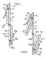
- a first separating member (10) is provided mounted and operated as in the embodiment of Figures 1 and 2, except that each actuator (18) extends downwardly instead of upwardly from support (20) on the mounting member (15) to support (19) on the frame.
- a second separating member (10a) is supported in a frame (11a) pivoted at its lower boundary surface by hinges (17a) to mounting member (15).
- the second separating member (10a) which is disposed below separating member (10) and associated with an opening (14a) below opening (14), is operated by actuator(s) (18a) by which it can be moved between closed and open positions.
- the two separating means may be moved simultaneously, separately, or one separating means may move while the second separating means may remain fixed.
- separating means (10) supported in frames (11), move from the first (closed) position to the second (open) position, against the air flow.
- separating members (10) and (10a) supported in frames (11) and (11a), respectively may move from the first (closed) position to the second (open) position, only against the air flow, and may move simultaneously or separately, such that:
- the separating members (10) and (10a) supported in frames (11) and (11a) may be located, optionally, in the same plane of the separator assembly, in a parallel plane of the separator assembly, or in a series of two or more parallel planes of the separator assembly, with each of the separating members (10) and (10a) arranged to move either as a complete assembly within the frames (11) and (11a), or in a split configuration where part of each separating member moves and part of each separating member remains fixed.
- separating members (10) and (10a) may consist of two or more stages (21) supported in frames (11) and (11a), respectively.
- the first stage only of separating members (10) and (10a) may move from the first (closed) position to the second (open) position against the air flow.
- the last stage only of separating members (10) and (10a) may move from the first (closed) position to the second (open) position with the air flow.
- Movement of the first stage against the air flow may be independent of movement of the last stage with the air flow, or both first and last stages of the separating members (10) and (10a) may move simultaneously.
- the first stage, intermediate stage(s), if present, or the last stage may be fixed while the remaining stage or stages may move, as previously described.
- each of the described separating members (10) and (10a) supported in frames (11) and (11a), respectively, may be pivoted to the mounting member (15) about an axis extending in a direction transverse to the direction of the air flow by hinges (17) and (17a) on any boundary surface such that the separating member(s) may be swung from the first (closed) position of Figure 5 to the second (open) position of Figure 6.
- the hinges might be provided along the upper boundary surface, the lower boundary surface, either of the side boundary surfaces, or one or more of the aforesaid boundary surfaces of the frame.
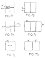
- Figures 7a, 7b and 7c are schematic top, front and side views of an embodiment of a separator assembly in its first (closed) position, with one fixed separator means (32) and one additional separator means (34) arranged for horizontal translation.
- the moveable separator means (34) moves to its second (open) position, either behind the fixed separator means (32) as shown in Figures 7f and 7g or into the wall of the air intake air duct, as shown in Figures 7h and 7i.
- the separator assembly In either the open or closed position, the separator assembly is horizontally transverse with respect to the direction of the air flow.
- the fixed separator means (32) may be located, either as shown in Figures 7a, 7b and 7c, or may be opposite handed, with the fixed separator means mounted on the right as viewed in Figure 7a.
- the moveable separator means (34) may be located either before or after the fixed separator means, relative to the air flow.
- the fixed separator means (32) may optionally consist of one or more separator assemblies (33), located in left-handed ( Figure 7d), right-handed (Figure 7d in dotted outline) or left to right diagonally arranged or right to left diagonally arranged ( Figure 7e) configurations arranged with moveable separator means (35) of equal number, all collectively arranged horizontally transverse to the direction of the air flow.
- Figures 7j through 7m show variations of the embodiment illustrated in Figure 7b.
- Figure 7j there is no fixed moisture separator, and one moveable moisture separator (34 ⁇ ) is provided which moves between its first position (closed) as shown in Figure 7j and its open position as shown in Figure 7k. It will be appreciated that the moveable moisture separator (34 ⁇ ) can move either to its left or its right into the air duct wall.
- Figure 71 there is, again, no fixed moisture separator, but instead two moveable moisture separators (35 ⁇ , 36 ⁇ ) are provided in the duct which can each move left or right into the air duct wall, as shown in Figure 7m.
- a yet further possible variation is similar to that shown in Figures 7d and 7e, but with additional moisture separator means arranged in left-handed or right-handed configurations, or arranged left to right diagonally or right to left diagonally, and configured to permit all moisture separators to move separately or collectively.
- Figures 8a, 8b and 8c are schematic top, front and side views of another embodiment of a separator assembly in its first (closed) position, with one fixed separator means (36) and one additional separator means (38) arranged for vertical translation.
- the moveable separator means (38) moves to its second (open) position, either as shown in Figures 8f and 8g or into the wall of the air intake air duct, as shown in Figures 8h and 8i. In either position, the separator assembly would be vertically transverse with respect to the direction of the air flow.
- the fixed separator means (36) may be located, either as shown in Figures 8a, 8b and 8c, or may be opposite handed, with the positions of fixed separator means and the moveable separator means as viewed in Figure 8c interchanged so that the fixed separator means is upstanding from a lower duct surface (37).
- the moveable separator means (38) may be located either before or after the fixed separator means, relative to the air flow.
- the fixed separator means (36) may optionally consist of one or more separator assemblies (39), located in upper-handed ( Figure 8d), lower-handed ( Figure 8d in dotted line) or left to right diagonally arranged or right to left diagonally arranged ( Figure 8e) configurations, arranged with moveable separator means (41) of equal number, all collectively arranged vertically transverse to the direction of the air flow.
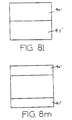
- FIGs 8j through 8m show variations of the embodiment illustrated in Figure 8b.
- there is no fixed moisture separator and instead one moveable moisture separator (38 ⁇ ) is shown which is moveable from its first closed position shown in Figure 8j to its second open position shown in Figure 8k.
- the moisture separator (38 ⁇ ) can move either up or down into the air duct wall.
- the embodiment illustrated in Figure 81 again has no fixed moisture separator, but instead has two moveable moisture separators (40 ⁇ and 41 ⁇ ).
- the two moveable moisture separators (40 ⁇ , 41 ⁇ ) are shown in their first closed position in Figure 81, and in their open position in Figure 8m, where the moisture separators have move upwardly and downwardly respectively into the air duct wall.
- a yet further possible variation is similar to the embodiment illustrated in Figures 8d and 8e, but with additional moisture separator means arranged in upper-handed or lower-handed configurations, or arranged left to right diagonally or right to left diagonally.
- the moisture separator means are all arranged so that they may move separately or collectively.
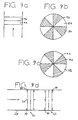
- Figures 9a, 9b, 9c and 9d are schematic top, front and side views of another embodiment of a separator assembly with two identical sectored wheels (44) (46) each having an equal number of separator sectors (48) (50) and an equal number of open sectors (52) (54) arranged for rotational translation.
- the separator sectors (48) (50) in each wheel are non-axially aligned such that the separator sectors (48) (50) collectively present a continuous circular separator assembly transverse to the direction of the air flow.
- one or the other wheel (44) (46) or both rotate, either clockwise or counter-clockwise, placing the separator sectors (48) of the one wheel directly behind the separator sectors (50) of the second wheel, and leaving the intervening open sectors (52) (54) open to the free passage of air bypassing the separator sectors (48, 50).
- the dual sectored wheels may be arranged in any one of the following arrangements:
- the sectored wheels with separator means may consist of two or more separator assemblies (60, 62), located axially in series, and having a common axis (64) parallel to the direction of the air flow.
- duct work (65) carrying the incoming air to the circular separator assembly may be circular or rectangular. In the latter case, corner fillets (58) will be required to seal the spaces between the rectangular duct and the circular separator assembly.
- Figures 10a, 10b, 10c and 10d are views of an alternate embodiment of rotational translation of a separator assembly in its first (closed) position, with one moveable separator means (66) arranged for rotational translation about an axis (67) located in any boundary edge of the intake air duct wall (68), said separator means (66) having the axis of rotation parallel to the air flow.
- the moveable separator means (66) moves from its first (closed) position to its second (open) position on its axis, rotationally transverse to the direction of the air flow, in either a clockwise or counter-clockwise direction, into the air duct wall.
- the power-applying means (18) may be pneumatic, hydraulic, electric or manually-powered actuators, used singly or in combination, mounted in various positions other than those shown.
- the pressure drop across the separating means (10) may be sensed with appropriate means, such as, for example, pressure sensors (22, 23) and a differential pressure switch or controller (24). If a high limit is reached, the actuator(s) (18) may be automatically operated to move the separating means into the open position, simultaneously, separately, or with an appropriate time delay means operating the actuator(s) sequentially.
- the separating means in any of the embodiments as described in the present application may include vanes only, impactors only, coalescers only, or any combination of impactors, coalescers and vanes.
- a vane is an inertial device which causes a fluid stream, such as an air stream, to change direction, and thereby impart inertial energy to particles contained in the stream as a result of the change in direction.
- An impactor is a device for separating particles from a stream utilizing the impaction theory, and may, for example, include several lavers of knitted mesh material which capture particles entrained in the stream as the stream passes through the impactor.
- a coalescer is a device which coalesces droplets in a stream to form larger droplets which then drop off the coalescer.
- all of the stages (21) may be vanes only, coalescers only, or impactors only, or each of the stages (21) may be independently selected from vanes (or any other type of inertial device), impactors and/or coalescers.
- vanes or any other type of inertial device
- impactors and/or coalescers may remain fixed when one or more of the stages move.
- the gasket (13) may be fabricated of any suitable material (eg., silicone rubber, natural rubber, synthetic rubber, plastics or similar material) that will provide the required sealing surface.
- the gasket may, if desired, be heated to prevent ice formation and sticking at the seal interface.
- Separator assemblies in accordance with the invention, may be fabricated from any metal, plastics, synthetic or other material or combination of materials having suitable properties.
Landscapes
- Engineering & Computer Science (AREA)
- Chemical & Material Sciences (AREA)
- Combustion & Propulsion (AREA)
- Chemical Kinetics & Catalysis (AREA)
- Mechanical Engineering (AREA)
- General Engineering & Computer Science (AREA)
- Analytical Chemistry (AREA)
- General Chemical & Material Sciences (AREA)
- Oil, Petroleum & Natural Gas (AREA)
- Separating Particles In Gases By Inertia (AREA)
Claims (50)
Priority Applications (1)
| Application Number | Priority Date | Filing Date | Title |
|---|---|---|---|
| AT86900357T ATE60912T1 (de) | 1985-10-02 | 1985-11-06 | Trenneinheit. |
Applications Claiming Priority (2)
| Application Number | Priority Date | Filing Date | Title |
|---|---|---|---|
| US78303785A | 1985-10-02 | 1985-10-02 | |
| US783037 | 1985-10-02 |
Publications (3)
| Publication Number | Publication Date |
|---|---|
| EP0240500A1 EP0240500A1 (de) | 1987-10-14 |
| EP0240500A4 EP0240500A4 (de) | 1988-04-11 |
| EP0240500B1 true EP0240500B1 (de) | 1991-02-20 |
Family
ID=25127982
Family Applications (1)
| Application Number | Title | Priority Date | Filing Date |
|---|---|---|---|
| EP19860900357 Expired EP0240500B1 (de) | 1985-10-02 | 1985-11-06 | Trenneinheit |
Country Status (4)
| Country | Link |
|---|---|
| EP (1) | EP0240500B1 (de) |
| AU (1) | AU5309186A (de) |
| DE (1) | DE3581811D1 (de) |
| WO (1) | WO1987001959A1 (de) |
Cited By (1)
| Publication number | Priority date | Publication date | Assignee | Title |
|---|---|---|---|---|
| WO2014164128A1 (en) * | 2013-03-11 | 2014-10-09 | Bha Altair, Llc | Automatic coalescer replacement system and method |
Families Citing this family (4)
| Publication number | Priority date | Publication date | Assignee | Title |
|---|---|---|---|---|
| US8721755B2 (en) | 2010-07-02 | 2014-05-13 | Bha Altair, Llc | Fog and mist catching apparatus |
| US8568504B2 (en) * | 2011-04-08 | 2013-10-29 | General Electric Company | Moisture reducing apparatus |
| FR2983085B1 (fr) * | 2011-11-28 | 2013-12-27 | Aaf France | Dispositif d'actionnement de filtres montes pivotants, ensemble filtre d'entree d'air le comportant et procede de commande d'un dispositif d'actionnement de filtres |
| ITCO20120007A1 (it) | 2012-02-21 | 2013-08-22 | Nuovo Pignone Srl | Dispositivo di filtraggio dell'aria in ingresso per un impianto |
Family Cites Families (18)
| Publication number | Priority date | Publication date | Assignee | Title |
|---|---|---|---|---|
| DE433056C (de) * | 1923-06-06 | 1926-08-19 | Willi Bartel | Luftfilter |
| US1914667A (en) * | 1931-06-29 | 1933-06-20 | Holland Furnace Co | Air filter |
| US2135750A (en) * | 1938-03-11 | 1938-11-08 | Harding Margaret | Air filter for wall registers |
| US2303333A (en) * | 1940-02-19 | 1942-12-01 | W B Connor Engineering Corp | Air purifying and circulating device |
| US2783786A (en) * | 1955-10-19 | 1957-03-05 | Clarence F Carter | Apparatus for filling collapsible containers |
| US3410288A (en) * | 1963-05-01 | 1968-11-12 | Kaiser Ind Corp | Relief valve for flue system |
| US3353551A (en) * | 1965-08-05 | 1967-11-21 | Gen Motors Corp | Air by-pass arrangement operated by differential air pressure |
| US3411272A (en) * | 1966-02-07 | 1968-11-19 | Michigan Dynamics Inc | Automatic fluid bypass sensing, actuating, and indicating system |
| US3421296A (en) * | 1966-11-15 | 1969-01-14 | United Aircraft Corp | Engine inlet air particle separator |
| US3593503A (en) * | 1969-05-27 | 1971-07-20 | Mine Safety Appliances Co | Side-loading filtering apparatus |
| US3612024A (en) * | 1969-11-03 | 1971-10-12 | John C Bandimere | Air cleaner bypass arrangement |
| US3733814A (en) * | 1972-02-22 | 1973-05-22 | Gen Electric | Translatable engine inlet particle separator |
| US3823532A (en) * | 1973-11-14 | 1974-07-16 | Combustion Eng | Filter |
| US4081255A (en) * | 1976-08-16 | 1978-03-28 | Evans Gary L | System for filtering stack gases |
| US4231769A (en) * | 1978-02-21 | 1980-11-04 | Ahlrich Willard K | Filtered ventilating system |
| US4312645A (en) * | 1980-03-10 | 1982-01-26 | Parmatic Filter Corporation | Separator assembly |
| US4361423A (en) * | 1980-11-03 | 1982-11-30 | Nkn | Combination acoustical muffler and exhaust converter |
| GB8412594D0 (en) * | 1984-05-17 | 1984-06-20 | Parmatic Filter Corp | Separator assembly |
-
1985
- 1985-11-06 EP EP19860900357 patent/EP0240500B1/de not_active Expired
- 1985-11-06 AU AU53091/86A patent/AU5309186A/en not_active Abandoned
- 1985-11-06 DE DE8686900357T patent/DE3581811D1/de not_active Expired - Fee Related
- 1985-11-06 WO PCT/US1985/002187 patent/WO1987001959A1/en not_active Ceased
Cited By (1)
| Publication number | Priority date | Publication date | Assignee | Title |
|---|---|---|---|---|
| WO2014164128A1 (en) * | 2013-03-11 | 2014-10-09 | Bha Altair, Llc | Automatic coalescer replacement system and method |
Also Published As
| Publication number | Publication date |
|---|---|
| DE3581811D1 (de) | 1991-03-28 |
| AU5309186A (en) | 1987-04-24 |
| EP0240500A1 (de) | 1987-10-14 |
| EP0240500A4 (de) | 1988-04-11 |
| WO1987001959A1 (en) | 1987-04-09 |
Similar Documents
| Publication | Publication Date | Title |
|---|---|---|
| US4698078A (en) | Separator assembly | |
| US4312645A (en) | Separator assembly | |
| EP1910168B1 (de) | Motorsaugmodultürsteuerung | |
| US20150135661A1 (en) | Louver device for removing moisture and dust | |
| DE3520413C2 (de) | ||
| EP2969764B1 (de) | Auswechselbares einlassschutzsysteme für lufteinlass von flugtriebwerken und zugehörige verfahren | |
| CA1120733A (en) | Swinging door particle separator and deicing system | |
| KR102069251B1 (ko) | 발전소용 입구 공기 필터 장치 | |
| EP1666709A2 (de) | Luftansaugsystem für eine Gasturbine und Methode zur Luftfilterung | |
| CH717534B1 (de) | Luftfiltervorrichtung des Brennstoffzellenfahrzeugs für extrem kalte Umgebungen und Luftfilterverfahren davon. | |
| RU2621108C2 (ru) | Устройство приведения в движение фильтров, установленных с возможностью поворота, блок фильтрации воздухозаборника, в состав которого оно входит, и способ управления устройством приведения в движение фильтров | |
| CA1288063C (en) | Separator assembly | |
| WO1987001959A1 (en) | Separator assembly | |
| SE440856B (sv) | Sett att filtrera bort fasta fororeningar ur gaser och anordning for genomforande derav | |
| GB2182582A (en) | Separator with by-pass means | |
| EP1029202B1 (de) | Regenerativer wärmetauscher | |
| DE102014105059A1 (de) | Verbesserter Ladeluftkühler für einen Motor | |
| EP0075054B1 (de) | Trennungsanlage | |
| US11111024B2 (en) | Foldable RAM air inlet filter | |
| KR890003354B1 (ko) | 분리기 조립체 | |
| GB2136311A (en) | Air intake equipment | |
| KR200278268Y1 (ko) | 여과포집진기용로타리밸브의공기역류방지장치 | |
| Sammak | Anti-icing in gas turbines | |
| CN118980615A (zh) | 一种大气环境颗粒物污染监测仪 | |
| SU1210857A1 (ru) | Запорное устройство дл перекрыти воздуховода |
Legal Events
| Date | Code | Title | Description |
|---|---|---|---|
| PUAI | Public reference made under article 153(3) epc to a published international application that has entered the european phase |
Free format text: ORIGINAL CODE: 0009012 |
|
| AK | Designated contracting states |
Kind code of ref document: A1 Designated state(s): AT BE CH DE FR GB IT LI LU NL SE |
|
| 17P | Request for examination filed |
Effective date: 19871002 |
|
| A4 | Supplementary search report drawn up and despatched |
Effective date: 19880411 |
|
| 17Q | First examination report despatched |
Effective date: 19890208 |
|
| GRAA | (expected) grant |
Free format text: ORIGINAL CODE: 0009210 |
|
| AK | Designated contracting states |
Kind code of ref document: B1 Designated state(s): AT BE CH DE FR GB IT LI LU NL SE |
|
| PG25 | Lapsed in a contracting state [announced via postgrant information from national office to epo] |
Ref country code: AT Effective date: 19910220 |
|
| REF | Corresponds to: |
Ref document number: 60912 Country of ref document: AT Date of ref document: 19910315 Kind code of ref document: T |
|
| REF | Corresponds to: |
Ref document number: 3581811 Country of ref document: DE Date of ref document: 19910328 |
|
| ITF | It: translation for a ep patent filed | ||
| ET | Fr: translation filed | ||
| PG25 | Lapsed in a contracting state [announced via postgrant information from national office to epo] |
Ref country code: SE Effective date: 19911107 |
|
| PGFP | Annual fee paid to national office [announced via postgrant information from national office to epo] |
Ref country code: FR Payment date: 19911129 Year of fee payment: 7 |
|
| PG25 | Lapsed in a contracting state [announced via postgrant information from national office to epo] |
Ref country code: LU Free format text: LAPSE BECAUSE OF NON-PAYMENT OF DUE FEES Effective date: 19911130 Ref country code: LI Effective date: 19911130 Ref country code: CH Effective date: 19911130 Ref country code: BE Effective date: 19911130 |
|
| PLBE | No opposition filed within time limit |
Free format text: ORIGINAL CODE: 0009261 |
|
| STAA | Information on the status of an ep patent application or granted ep patent |
Free format text: STATUS: NO OPPOSITION FILED WITHIN TIME LIMIT |
|
| 26N | No opposition filed | ||
| BERE | Be: lapsed |
Owner name: PARMATIC FILTER CORP. Effective date: 19911130 |
|
| REG | Reference to a national code |
Ref country code: CH Ref legal event code: PL Ref country code: CH Ref legal event code: AUV Free format text: LE BREVET CI-DESSUS EST TOMBE EN DECHEANCE FAUTE DE PAIEMENT, DE LA 7E ANNUITE. |
|
| PG25 | Lapsed in a contracting state [announced via postgrant information from national office to epo] |
Ref country code: FR Effective date: 19930730 |
|
| REG | Reference to a national code |
Ref country code: FR Ref legal event code: ST |
|
| EUG | Se: european patent has lapsed |
Ref document number: 86900357.4 Effective date: 19920604 |
|
| PGFP | Annual fee paid to national office [announced via postgrant information from national office to epo] |
Ref country code: NL Payment date: 19961130 Year of fee payment: 12 |
|
| PG25 | Lapsed in a contracting state [announced via postgrant information from national office to epo] |
Ref country code: NL Free format text: LAPSE BECAUSE OF NON-PAYMENT OF DUE FEES Effective date: 19980601 |
|
| NLV4 | Nl: lapsed or anulled due to non-payment of the annual fee |
Effective date: 19980601 |
|
| PGFP | Annual fee paid to national office [announced via postgrant information from national office to epo] |
Ref country code: GB Payment date: 20011112 Year of fee payment: 17 |
|
| PGFP | Annual fee paid to national office [announced via postgrant information from national office to epo] |
Ref country code: DE Payment date: 20011119 Year of fee payment: 17 |
|
| REG | Reference to a national code |
Ref country code: GB Ref legal event code: IF02 |
|
| PG25 | Lapsed in a contracting state [announced via postgrant information from national office to epo] |
Ref country code: GB Free format text: LAPSE BECAUSE OF NON-PAYMENT OF DUE FEES Effective date: 20021106 |
|
| PG25 | Lapsed in a contracting state [announced via postgrant information from national office to epo] |
Ref country code: DE Free format text: LAPSE BECAUSE OF NON-PAYMENT OF DUE FEES Effective date: 20030603 |
|
| GBPC | Gb: european patent ceased through non-payment of renewal fee |