EP0240427A2 - Verfahren und Vorrichtung zum Destillieren von Meerwasser - Google Patents
Verfahren und Vorrichtung zum Destillieren von Meerwasser Download PDFInfo
- Publication number
- EP0240427A2 EP0240427A2 EP87400706A EP87400706A EP0240427A2 EP 0240427 A2 EP0240427 A2 EP 0240427A2 EP 87400706 A EP87400706 A EP 87400706A EP 87400706 A EP87400706 A EP 87400706A EP 0240427 A2 EP0240427 A2 EP 0240427A2
- Authority
- EP
- European Patent Office
- Prior art keywords
- sea water
- circuit
- water
- distilled water
- seawater
- Prior art date
- Legal status (The legal status is an assumption and is not a legal conclusion. Google has not performed a legal analysis and makes no representation as to the accuracy of the status listed.)
- Withdrawn
Links
Images


Classifications
-
- C—CHEMISTRY; METALLURGY
- C02—TREATMENT OF WATER, WASTE WATER, SEWAGE, OR SLUDGE
- C02F—TREATMENT OF WATER, WASTE WATER, SEWAGE, OR SLUDGE
- C02F1/00—Treatment of water, waste water, or sewage
- C02F1/02—Treatment of water, waste water, or sewage by heating
- C02F1/04—Treatment of water, waste water, or sewage by heating by distillation or evaporation
- C02F1/06—Flash evaporation
-
- Y—GENERAL TAGGING OF NEW TECHNOLOGICAL DEVELOPMENTS; GENERAL TAGGING OF CROSS-SECTIONAL TECHNOLOGIES SPANNING OVER SEVERAL SECTIONS OF THE IPC; TECHNICAL SUBJECTS COVERED BY FORMER USPC CROSS-REFERENCE ART COLLECTIONS [XRACs] AND DIGESTS
- Y02—TECHNOLOGIES OR APPLICATIONS FOR MITIGATION OR ADAPTATION AGAINST CLIMATE CHANGE
- Y02A—TECHNOLOGIES FOR ADAPTATION TO CLIMATE CHANGE
- Y02A20/00—Water conservation; Efficient water supply; Efficient water use
- Y02A20/124—Water desalination
Definitions
- the present invention relates to a process and an installation for distilling seawater.
- the invention aims to significantly improve the distillation performance, in particular from the point of view of distilled water yield for a given quantity of seawater and from the energy point of view.
- the invention provides a seawater distillation system derived from the combination of the MSF system and a cylindro-flash system, in which the water which enters the evaporation cells has two modes of introduction which can be separated or combined.
- the first consists of a flashing tablecloth as in the case of the multiflash system; the second consists of a directed and flashing multijet method (plurality of jets driven back at high temperature in a vacuum enclosure.) These two modes are normally operated simultaneously. This has the effect of increasing the production capacity of distilled water with the use of the same amount of seawater to be desalted and the same amount of heating calorific energy used by conventional units. This increase is of the order of 3/4 of current actual production.
- the invention thus proposes a process for the distillation of sea water according to which sea water is taken, this sea water is heated and it is evaporated in a sealed enclosure in which a continuous extraction of gas is carried out, the sea water circulating in this enclosure with a view to its evaporation by expansion in the form of sheets, on the one hand, and in the form of multiple directed jets, on the other hand, the resulting water vapor is condensed and collected distilled water thus produced.
- the invention also provides a seawater distillation installation comprising: - a sealed enclosure comprising a condensation stage with condensers and seawater passages, and an evaporation stage, - a seawater supply circuit connected to the entrance to the seawater passages, - a heating circuit with a boiler for heating the sea water leaving the sea water passages before it circulates in the evaporation stage, - parallel sea water circulation channels in the evaporation stage in the form of multiple directed jets, on the one hand, and aquifers, on the other hand, a gas extraction circuit connected to the sealed enclosure to allow evaporation by relaxation of the sea water from the jets and the layers, and - a distilled water sampling circuit.
- the invention also relates to a new seawater ejection device in the form of a directed and flashing multijet.
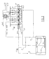
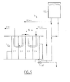
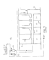
- the seawater desalination installation shown in FIG. 8 by way of nonlimiting example mainly comprises an evaporation / condensation station 1, a brine heating boiler 2, a seawater supply circuit 3, a distilled water discharge circuit 4, a chemical treatment circuit for sea water 5, a chemical treatment circuit for distilled water 6, and a gas extraction circuit 7.
- the evaporation / condensation station 1 which constitutes the heart of the installation comprises a sealed enclosure 8 made of PRFV in which several cells are provided side by side, here 4 in number and referenced C1, C2, C3 and C4. This station consists of an upper condensation stage 1A and a lower evaporation stage 1B.
- Each cell is equipped with a condenser 9, a gas extractor 10, a brine passage 11 and separators so-called magic 12 (these are filters which allow only steam and non-condensable gases to pass through and do not allow charged brine droplets to pass).
- the cells are independent from each other from the point of view of absolute pressure and temperature.
- the lower stage of station 1 has a first level of multi-flash MSF evaporation with baffles and a second level located immediately above called cylindro-flash (denoted CF), these levels being adapted to be supplied simultaneously with brine .
- this cylindro-flash comprises two parallel distribution manifolds 13A and 13B (in FRP) connected by horizontal parallel flashing cylinders 14 at the rate of one pair of cylinders per cell (i.e. a total of 8).
- These collectors are supplied with brine at high temperature, from the boiler 2, by two delivery pumps 15.
- a balancing tube 16, equipped with a pressure gauge 17 is disposed between the outputs of these pumps.
- the flashing evaporation cylinders 14 are drilled from place to place of convergent-divergent holes, partially facing each other within each cell, intended to spray hot brine into the cells according to the inclined arrows of FIGS. 2 and 8.
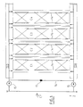
- the jets of pulverized brine escaping partly opposite the cylinders contained in this cell, represented by triangles in FIG. 1, converge and cause, in their contact zones, a release of vapor towards the condensers.
- between the triangles are steam exhaust zones to these condensers.
- the reheating boiler 2 (see FIG. 2) constitutes a sealed volume in a GRP enclosure.
- a condenser is mounted therein between two water boxes (GFRP) called the condenser inlet box and the condenser outlet box.
- Two electrical resistors 18 are mounted in the boiler for heating the sea water.
- This boiler receives in 19 sea water (brine) having circulated in cells C1 to C4 and supplies in 20, sea water hot for the evaporation stage.
- a return circuit 21 (by-pass) is connected between the pipes 19 and 20 and allows recycling of sea water for additional heating. This results in an economy of heating energy and a better use of it.
- the outlet pipe 20 is separated into two branches 20A and 20B respectively leading to the cylindro-flahs CF and to the multiflash level.
- the distribution of seawater between these 2 branches is controlled by a pump 22 (not shown in Figure 2).
- PRFV closed circuit 23
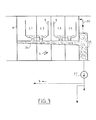
- a corridor of distilled water 24 (in PRFV) into which the condensers 9 of each cell open out through flow holes (see FIG. 3). It is a system isolated from other elements, which eliminates any risk of mixing brine water with distilled water at the time of flash flash.
- the distilled water circuit 4 further comprises an accumulation tank 25 into which the corridor 24 opens.
- a circuit 26 for returning steam to the last condenser allows recovery by internal extraction in the cell. This has the effect of recondensing the vapor produced by the gravity flow of the distilled water from the corridor 24 into the tank 25.
- a pump 27 for extracting distilled water pumps the distilled water to a storage tank (not shown), to circuit 6 or, for example to a rejection channel.
- the gas extraction circuit 7, or vacuum circuit includes pipes made of stainless steel or GRP. It is intended for the extraction of non-condensable gases formed in the cells at the time of evaporation and condensation as well as the air contained in the make-up water (sea water).
- this extraction takes place at two points: a first tube 28 extracts the qaz from cells C1 and C2 while a second tube 29 leaves from cell C4.
- This circuit also includes a tube 30 for connection to an additional ramp 35 (see below).
- These various pipes are connected to ejectors E1 and E2 for maintaining vacuum ensuring extraction.
- These ejectors work by means of a seawater discharge, by means of a pump 31 (they can, as a variant, work in a closed circuit, the gases being ejected into a reservoir from which the fluid is withdrawn. ejection).
- the vacuum is produced using a water pump and ejectors (case without combination); but if the unit is combined, the circuit automatically changes at will.
- the sea water supply circuit 3, or water make-up circuit mainly comprises a main tank 33 supplied with sea water by a pump 34 (see FIG. 8) and a set of pipes connected to the condensers of the cells C1 and C4. It is connected to an intermediate tank 35 (auxiliary ramp). A feed circuit for this ramp is connected to the main tank in order to maintain the production level (feed rate) of the water to be desalinated.
- the make-up ramp is in direct connection with the suction inlet of a recirculation pump 36 (see Figure 8) allowing the discharge to the condensers of a mixture of make-up water and treated brine.
- the brine recovered at the bottom of the evaporation stage of station 1 is discharged towards the ramp 35 (or rejected) by another recirculation pump 37. As an adjunct, it is also supplied directly from the tank 33.
- an auxiliary tube allows the addition of sea water (or raw water) to the sea water leaving the condensers from the main tank.
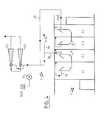
- the intermediate tank 35 also leads to the circuit 5 for injecting a chemical agent for treating seawater (see FIG. 6).
- the circuit includes a chemical reagent reservoir 40 containing a mixture of polyphosphates and antifoam. This mixture has the function of fluidizing the mud and distorting the crystalline germs of calcium carbonate (CaCO3) by preventing their growth by purely physical action.
- the calcium carbonate which concentrates beyond 60 degrees is neutralized by the polyphosphate (at less than 60 degrees the calcium carbonate is rejected by the pressure of sea water in the condensers).
- Antifoam is added to prevent seawater from overflowing from the magic separators during boiling.
- This mixture is injected into seawater, in the make-up tank 35, by ejectors E3 and E4, the working fluid of which is brine water (to be treated) discharged by the recirculation pump 37 ; a brine-polyphosphate-anti-foam mixture is produced.
- the circuit 6 for chemical treatment of distilled water comprises a reservoir 41 of caustic soda connected to a bypass piping connected to the corridor of distilled water 24 and to the outlet of the reservoir 25 for accumulating distilled water.
- Caustic soda is injected into this piping by ejectors E5 and E6, the working fluid of which is distilled water discharged into this piping by pump 27.
- This caustic soda helps fight against corrosion of distilled water pipes (formation a protective layer) and an increase in the hydrogen potential (pH); there is also an increase in the temperature of the distilled water in order to recover the steam to be recycled for recondensation.
- the soda can be injected by a pump towards the inlet of the distilled water corridor and towards the reservoir 25 for accumulation of distilled water through valves.
- the injection of the chemicals is preferably done by means of ejectors (which can work in a closed circuit) in which the working fluid is the water to be treated, whereas, in a conventional manner, metering pumps are used in which cavitation occurs and the thermal effect of the distillation unit is reduced to less than 40%.
- the start-up of the installation in Figure 8 begins with filling all the circuits with sea water (35 to 55 g of salt / liter).
- the vacuum circuit 7 is started: there is an extraction of air by the electors E1 and E2, the working fluid of which is seawater discharged by the pump 31. This extraction of gas occurs in the reservoir make-up 35, in cells 1 and 2, and in cells 1 to 4.
- the injection of polyphosphate and antifoam is started and switches on the boiler 2 until a temperature of 45 ° is reached in cells 1 and 2, thus allowing the production of the first droplets of distilled water and a few grams of non-condensable gases.
- the latter are discharged into the atmosphere through the vacuum maintenance ejectors E1 and E2 and the evaporator circuits.
- This first quantity of distilled water produced will be discharged into the sea.
- the vapor generating exchange surface is increased, as is the total quantity of steam supplied and therefore the total quantity of distilled water obtained.
- the temperature at the outlet of the heater is maintained at 90 ° with extraction of the non-condensable gases from the complete unit by the cells C1, C2, C3 and C4.
- Such a system is capable of bringing the ratio ⁇ between the production of distilled water and the amount of seawater to be desalted to 2.06. This constitutes a growth of the order of 3/4 compared to the production carried out by conventional MSF type desalination units.
Landscapes
- Life Sciences & Earth Sciences (AREA)
- Hydrology & Water Resources (AREA)
- Engineering & Computer Science (AREA)
- Environmental & Geological Engineering (AREA)
- Water Supply & Treatment (AREA)
- Chemical & Material Sciences (AREA)
- Organic Chemistry (AREA)
- Heat Treatment Of Water, Waste Water Or Sewage (AREA)
Applications Claiming Priority (2)
| Application Number | Priority Date | Filing Date | Title |
|---|---|---|---|
| TN86046 | 1986-04-01 | ||
| TN86046 | 1986-04-01 |
Publications (2)
| Publication Number | Publication Date |
|---|---|
| EP0240427A2 true EP0240427A2 (de) | 1987-10-07 |
| EP0240427A3 EP0240427A3 (de) | 1988-07-27 |
Family
ID=21618061
Family Applications (1)
| Application Number | Title | Priority Date | Filing Date |
|---|---|---|---|
| EP87400706A Withdrawn EP0240427A3 (de) | 1986-04-01 | 1987-03-31 | Verfahren und Vorrichtung zum Destillieren von Meerwasser |
Country Status (3)
| Country | Link |
|---|---|
| EP (1) | EP0240427A3 (de) |
| JP (1) | JPS62241591A (de) |
| DE (1) | DE240427T1 (de) |
Cited By (1)
| Publication number | Priority date | Publication date | Assignee | Title |
|---|---|---|---|---|
| WO2002100510A1 (en) * | 2001-06-12 | 2002-12-19 | Vivendi Water Systems Limited | Improvements relating to degassing liquids |
Family Cites Families (5)
| Publication number | Priority date | Publication date | Assignee | Title |
|---|---|---|---|---|
| US3388045A (en) * | 1964-10-12 | 1968-06-11 | Aqua Chem Inc | Multistage flash evaporator distillation apparatus and method and condenser with spray film effects |
| US3783108A (en) * | 1971-01-18 | 1974-01-01 | R Saari | Method and apparatus for distilling freshwater from seawater |
| JPS5536361B2 (de) * | 1971-10-04 | 1980-09-20 | ||
| US3884767A (en) * | 1973-09-21 | 1975-05-20 | Jr John E Pottharst | Multi-effect flash evaporator |
| FR2409779A1 (fr) * | 1977-11-25 | 1979-06-22 | Commissariat Energie Atomique | Procede et dispositif de distillation a basse temperature |
-
1987
- 1987-03-31 EP EP87400706A patent/EP0240427A3/de not_active Withdrawn
- 1987-03-31 DE DE198787400706T patent/DE240427T1/de active Pending
- 1987-04-01 JP JP62080882A patent/JPS62241591A/ja active Pending
Cited By (1)
| Publication number | Priority date | Publication date | Assignee | Title |
|---|---|---|---|---|
| WO2002100510A1 (en) * | 2001-06-12 | 2002-12-19 | Vivendi Water Systems Limited | Improvements relating to degassing liquids |
Also Published As
| Publication number | Publication date |
|---|---|
| EP0240427A3 (de) | 1988-07-27 |
| DE240427T1 (de) | 1988-05-19 |
| JPS62241591A (ja) | 1987-10-22 |
Similar Documents
| Publication | Publication Date | Title |
|---|---|---|
| US4434057A (en) | Water purification utilizing plural semipermeable membrane stages | |
| US5316626A (en) | Process and apparatus for the production of fresh water using solar energy | |
| KR101602216B1 (ko) | 적층 구조를 갖는 강하 경막 증발 장치, 이를 포함하는 폐수 무방류 설비 및 이를 이용한 폐수 무방류 처리 방법 | |
| US20150232348A1 (en) | Water desalination and brine volume reduction process | |
| US20110266132A1 (en) | Air flow-circulation seawater desalination apparatus | |
| US3425235A (en) | Solvent purification | |
| FR2975479B1 (fr) | Dispositif d'evaporation/condensation | |
| JP2015150553A (ja) | 造水装置及び造水方法 | |
| EP1750823B1 (de) | Meerwasser-entsalzungsverfahren und -anlage unter verwendung von mehrfacheffekt-destillation mit mechanischer und thermischer dampfkompression | |
| JP2009072734A (ja) | 気流循環による海水の淡水化装置 | |
| WO2011124806A1 (fr) | Installation de dessalement d'eau de mer par distillation a effets multiples | |
| KR20180068465A (ko) | 태양광 및 폐열을 이용한 해수 담수화장치, 담수 및 천일염 제조장치 | |
| RU2078047C1 (ru) | Деаэратор | |
| RU2393995C1 (ru) | Способ опреснения морской воды и установка для опреснения морской воды | |
| EP0240427A2 (de) | Verfahren und Vorrichtung zum Destillieren von Meerwasser | |
| US3856631A (en) | Process and apparatus for separating water from non-volatile solutes | |
| US2027395A (en) | Water reclaimer | |
| US4668345A (en) | Desalination apparatus and method for recovering fresh water | |
| CN102134110A (zh) | 一种利用喷射器的低压太阳能海水淡化装置 | |
| CN220131932U (zh) | 一种太阳能海水淡化和精盐提炼装置 | |
| RU2359917C1 (ru) | Способ опреснения морской воды путем утилизации низкопотенциального тепла | |
| KR20240148155A (ko) | 재생 에너지원을 이용한 진공 버블링 담수화 시스템 | |
| FR2493171A1 (fr) | Bouilleur-evaporateur-concentrateur-distillateur atmospherique basse pression faible temperature | |
| FR2999950A1 (fr) | Dispositif et procede d'evaporation d'un liquide et leurs applications | |
| RU2280011C1 (ru) | Установка для опреснения соленой воды и способ опреснения соленой воды с использованием установки |
Legal Events
| Date | Code | Title | Description |
|---|---|---|---|
| PUAI | Public reference made under article 153(3) epc to a published international application that has entered the european phase |
Free format text: ORIGINAL CODE: 0009012 |
|
| AK | Designated contracting states |
Kind code of ref document: A2 Designated state(s): BE CH DE FR GB IT LI |
|
| GBC | Gb: translation of claims filed (gb section 78(7)/1977) | ||
| ITCL | It: translation for ep claims filed |
Representative=s name: BARZANO' E ZANARDO ROMA S.P.A. |
|
| DET | De: translation of patent claims | ||
| PUAL | Search report despatched |
Free format text: ORIGINAL CODE: 0009013 |
|
| AK | Designated contracting states |
Kind code of ref document: A3 Designated state(s): BE CH DE FR GB IT LI |
|
| STAA | Information on the status of an ep patent application or granted ep patent |
Free format text: STATUS: THE APPLICATION IS DEEMED TO BE WITHDRAWN |
|
| 18D | Application deemed to be withdrawn |
Effective date: 19890128 |