EP0240420B1 - A method for manufacturing a continuous-length extruded bar of plastic magnet with circumferentially multipolar magnetization - Google Patents
A method for manufacturing a continuous-length extruded bar of plastic magnet with circumferentially multipolar magnetization Download PDFInfo
- Publication number
- EP0240420B1 EP0240420B1 EP19870400682 EP87400682A EP0240420B1 EP 0240420 B1 EP0240420 B1 EP 0240420B1 EP 19870400682 EP19870400682 EP 19870400682 EP 87400682 A EP87400682 A EP 87400682A EP 0240420 B1 EP0240420 B1 EP 0240420B1
- Authority
- EP
- European Patent Office
- Prior art keywords
- circumferentially
- multipolar
- magnet
- plastic magnet
- magnetic
- Prior art date
- Legal status (The legal status is an assumption and is not a legal conclusion. Google has not performed a legal analysis and makes no representation as to the accuracy of the status listed.)
- Expired - Lifetime
Links
Images


Classifications
-
- H—ELECTRICITY
- H01—ELECTRIC ELEMENTS
- H01F—MAGNETS; INDUCTANCES; TRANSFORMERS; SELECTION OF MATERIALS FOR THEIR MAGNETIC PROPERTIES
- H01F41/00—Apparatus or processes specially adapted for manufacturing or assembling magnets, inductances or transformers; Apparatus or processes specially adapted for manufacturing materials characterised by their magnetic properties
- H01F41/02—Apparatus or processes specially adapted for manufacturing or assembling magnets, inductances or transformers; Apparatus or processes specially adapted for manufacturing materials characterised by their magnetic properties for manufacturing cores, coils, or magnets
- H01F41/0253—Apparatus or processes specially adapted for manufacturing or assembling magnets, inductances or transformers; Apparatus or processes specially adapted for manufacturing materials characterised by their magnetic properties for manufacturing cores, coils, or magnets for manufacturing permanent magnets
- H01F41/0273—Imparting anisotropy
- H01F41/028—Radial anisotropy
-
- H—ELECTRICITY
- H01—ELECTRIC ELEMENTS
- H01F—MAGNETS; INDUCTANCES; TRANSFORMERS; SELECTION OF MATERIALS FOR THEIR MAGNETIC PROPERTIES
- H01F7/00—Magnets
- H01F7/02—Permanent magnets [PM]
- H01F7/0205—Magnetic circuits with PM in general
- H01F7/021—Construction of PM
Definitions
- the present invention relates to a method for manufacturing a continuous-length extruded bar of plastic magnet with circumferentially multipolar magnetization by extrusion molding.
- Multipolar tubular permanent magnets can be manufactured by several different methods of magnetization of a bar material of a plastic magnet extruded without magnetization or extrusion molding through a multipolar magnetizer so that the extruded bar material of the plastic magnet is already magnetized.
- the methods include:
- the magnetic force of these three types of the permanent magnets is, as a general trend, in the decreasing order of circumferentially anisotropic magnets, radially anisotropic magnets and isotropic magnets. It is of course that control of a servo motor is easier when the inertia thereof is smaller and a smaller servomotor is preferable to larger ones assuming that the output force is the same. Accordingly, preferable multipolar tubular permanent magnets are of the type of the circumferentilally anisotropic magnets capable of generating a larger torque than the other types in order to design smaller and lighter motors.
- One of the conventional methods for the manufacture of a circumferentially anisotropic magnet is to fill the space between a core and a metal mold having a coil of a multipolar magnetizer with a powder of a magnetic material which is compression-molded by means of a pair of upper and lower punches while the magnet particles are magnetized by energizing the coil of the magnetizer.
- a method is disclosed in Japanese Patent Kokai 60-89717 by utilizing the techniques of injection molding.
- the scope of the present invention consists in manufacturing a continuous-length extruded bar of a plastic magnet having a high degree of orientation and multipolar circumferential anisotropy by mounting a multipolar, circumferentially anisotropic magnetizing member on the discharge port of an extruder machine and cutting the thus extruded continuous-length bar in a desired product length.
- the present invention provides a method for manufacturing a continuous-length extruded bar of a plastic magnet with circumferentially multipolar magnetization which comprises extruding a plastic magnet composition out of the discharge port of an extruder machine having a multipolar, circumferentially anisotropic magnetizing member which is constructed of a plural number of radially oriented sector-like magnetic pole plates formed of a magnetic material of a saturation magnetization of at least 10 kG (1,0 T) and a plural number of radially oriented sector-like permanent magnets, each pair of adjacent two thereof sandwiching one of the magnetic pole plates therebetween with the poles of the respective permanent magnets having the same polarity facing to each other, coaxially mounted thereon.
- FIGURES 1a and 1b are for the illustration of a multipolar tubular magnets magnetized either circumferential or radial direction, respectively.
- the present invention particularly relates to the former type of multipolar tubular magnet made of a plastic magnet composition.
- Figures 2a and 2b are for the illustration of a molding die assembly used in the conventional compression molding method for the preparation of a circumferentially anisotropic multipolar tubular magnet.
- the space formed between the core 3 and the metal mold 10 having a plural number of magnetizing coils 9 as a multipolar magnetizer is filled with a powder of the magnetic material, e.g. a plastic magnet composition, 8 which is compression-molded by means of the upper and lower punches 11, 11 while the powder is under magnetization by energizing the coils 9.
- a powder of the magnetic material e.g. a plastic magnet composition, 8 which is compression-molded by means of the upper and lower punches 11, 11 while the powder is under magnetization by energizing the coils 9.
- the method of the present invention is described in detail with reference to the other figures of the accompanying drawing.
- the method of the invention is practiced by using an extruder machine, which is provided with a sizing die having a multipolar, circumferentially anisotropic orientating magnetizing member mounted on the discharge port.
- This sizing die includes the circumferentially anisotropic multipolar orientating magnetizing member constructed, as is shown in FIGURE 3, by the assembly of a plural number of the sector-like permanent magnets 1 and a plural number of the magnetic pole plates 2 to surround the extruded material out of the discharge port of the extruder machine in such a magner that each pair of two adjacent pole plates 2 sandwiches one of the permanent magnets 1 therebetween or vice versa.
- the orientating magnetizing member is mounted firmly on the holder frame 4 to form a sizing die 7.
- the magnetic material 8 such as a plastic magnet composition
- the extruded bar material is subjected to anisotropic multipolar magnetization as it goes through the opening of the sizing die 7.
- FIGURE 3 illustrates an 8-polar member having eight permanent magnets 1 and eight pole plates 2, the number of the magnets is of course not limited thereto.
- the magnetic pole plates 2 should be mate of a material of high saturation magnetization of, preferably, at least 10 kG (1 T) or, more preferably, at least 15 kG (1,5 T) such as iron and alloys of iron and cobalt.
- a pole plate 2 is sandwiched by two sector-like permanent magnets 1 having the same polarity in the radial direction. Namely, the N-poles or S-poles of the two adjacent permanent magnets 1 face to each other with the pole plate 2 intervening therebetween and the magnets 1 and pole plates 2 are adhesively bonded together.
- the direction of magnetic orientation in the permanent magnets 1 should preferably be parallel to the base of the equilateral triangle formed by the two adjacent magnetic pole plates or perpendicular to the magnetic pole plates adjacent to each other by sandwiching the same.
- Each of the permanent magnets 1 should be so powerful that at least 15 kG (1,5 T) of the magnetic flix is obtained at the circumferential surface of the extruded material at the magnetic poles.
- the permanent magnet should also have a coercive force of a least 6 KOe (477,6 kA m ) and residual density of magnetic flux of at least 6 kG (0,6 T) with the coefficient of temperature dependency of the coercive force and magnetic flux of each 0.1%/°C or smaller.
- a coercive force of the permanent magnet smaller than 6 KOe (447,6 kA m ) means greater demagnetization thereof while a larger permanent magnet must be used when the density of the residual magnetic flux is smaller than 6 kG (0,6 T) resulting in an increase in the magnetic leakage along the magnetic circuit in each case.
- the coefficient of temperature dependency should be as small as possible because a magnetic material having a larger temperature dependency is subject to greater thermal demagnetization in the process of molding.
- Recommendable permanent magnet materials for the permanent magnets 1 in view of the above mentioned requirements include those of a rare earth-based magnet alloy or, in particular, samarium-cobalt magnet alloy though not particularly limitative thereto.
- the material of the magnetic pole plates 2 should have a saturation magnetization of at least 10 kG (1 T) or, preferably, at least 18 kG (1,8 T).
- the saturation magnetization of the material of the magnetic pole plates 2 is smaller than 10 kG (1,0 T), the magnetic leakage from the magnetic pole plates is increased so that the magnetic orientation in the extruded bar material may eventually be incomplete.
- the magnetic material molded according to the invention is a plastic magnet composition compounded of a fine powder of a permanent magnet such as rare earth-based magnets, ferrites and the like and a thermoplastic polymer as the matrix together with optional additives.
- the magnet powder should have an average particle diameter in the range from 0.5 to 100 ⁇ m or, preferably, from 1 to 40 ⁇ m.
- thermoplas-ticity Various kinds of polymers having thermoplas-ticity can be used as the matrix including polyethylenes, polypropylenes, polystyrenes, polyvinyl chlorides, acrylic resins, polyamides, polyphenylene sulfides, polyphenylene oxides, polyacetales, polyethylene terephthalates, polybutylene terephthalates, polycarbonates, polyester elastomers, polyurethane elastomers and the like.
- the plastic magnet composition should be compounded in such a proportion of 35 to 70% by volume or, preferably, 40 to 65% by volume of the magnet powder and 70 to 25% by volume or, preferably, 60 to 35% by volume of the thermoplastic polymer.
- the accompanying drawing and the Examples given below are directed to a manufacturing process of an extruded bar material having a circular or annular cross section, it is of course that the above described inventive method is applicable to the manufacturing process of any tubular bar materials having different cross sections such as tubes having a polygonal cross section.
- the present invention provides a very efficient method for manufacturing a continuous-length extruded bar of plastic magnet with circumferentially multipolar magnetization so that the inventive method is industrially very valuable.
- the method of the present invention is described in more detail by way of Examples.
- a plastic magnet composition was prepared by uniformly milling a mixture composed of 91% by weight or 58% by volume of a powdered rare earth-based permanent magnet (R-30, a product by Shin-Etsu Chemical Co.) having an average particle diameter of about 3.5 ⁇ m and 9% by weight or 42% by volume of a plasticized polyvinyl chloride resin compound (MF-200, a product by the same company, supra).
- the plastic magnet composition was shaped into a continuous-length tubular bar by extrusion molding using a 25 mm diameter extruder machine.
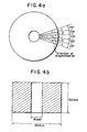
- the sizing die of the extruder machine was equipped with a multipolar, circumferentially anisotropic orientating magnetizing member as illustrated in FIGURES 4a and 4b.
- the orientating magnetizing member was constructed of 24 pieces of permanent magnets 1 made of the same R-30 rare earth magnet and 24 magnetic pole plates 2 made of pure iron having saturation magnetization of 21 kG (2,1 T) each in a sector-like form with a central angle of 7.5° and alternately arranged around the center axis as is illustrated in FIGURE 4a.
- the sizing die had dimensions of 18 mm of outer diameter, 16 mm of inner diameter and 50 mm of length as is shown in FIGURE 4b and the temperature thereof was controlled not to exceed 50°C.
- the extruder machine was run at 150°C with the screw rotated at a velocity of 60 rpm.
- a piece of plastic magnet with circumferentially multipolar magnetization was taken from the thus prepared continuous-length extruded bar material by cutting in a plane perpendicular to the axis and the distribution of magnetic open flux around the circumference was measured by using a gaussmeter to give the results shown in FIGURE 5 indicating that the tubular plastic maggnet with circumferentially multipolar maggnetization had a very high open flux of almost 2 kG (0,2 T).
- the same plastic magnet composition as used in the above described experiment was extrusion-molded into a continuous-length tube of the same dimensions as above without mounting the circumferentially orientating magnetizing member on the discharge port of the extruder maching.
- the thus obtained plastic magnet bar was subjected to circumferential multipolar magnetization using a 24-polar magnetization yoke having an inner diameter of 18.1 mm by energizing each magnetizing coil with discharge of a capacitor of 600 ⁇ F capacity charged at 2000 volts.
- the thus prepared multipolar circumferentially magnetized plastic magnet was subjected to the measurement of the magnetic open flux around the circumference in the same manner as above to find that the maximum value of the peaks in a chart similar to FIGURE 5 was about 1 kG (0,1 T).
- a plastic magnet composition was prepared by uniformly Kneading, in a kneader at 220°C, 45% by volume of a polyester elastomer having a hardness of 60 according to JIS K 6301 and 55% by volume of a powder of the same rare earth-based magnetic alloy as used in Example 1 having an average particle diameter of about 3.5 ⁇ m.
- This plastic magnet composition was extrusion-molded into a continuous-length tubular form of the same dimensions as in Example 1 with the die of which the temperature was controlled not to exceed 50 °C.
- the same circumferentially orientating magnetizing member as in Example 1 was mounted on the discharge port of the extruder machine which was run at 250°C.
Landscapes
- Engineering & Computer Science (AREA)
- Power Engineering (AREA)
- Manufacturing & Machinery (AREA)
- Physics & Mathematics (AREA)
- Electromagnetism (AREA)
- Manufacturing Cores, Coils, And Magnets (AREA)
- Extrusion Moulding Of Plastics Or The Like (AREA)
Description
- The present invention relates to a method for manufacturing a continuous-length extruded bar of plastic magnet with circumferentially multipolar magnetization by extrusion molding.
- It is a trend in recent years that control of higher and higher precision is required for various types of magnetic heads for picking up electronic and magnetic signals in robots and numerically controlled machines for factory automatization as well as in computers, VTRs and the like. Such high-precision control of magnetic heads is performed in many cases by means of a servomechanism using a stepping motor so that demand for multipolar tubular permanent magnets is rapidly increasing as an important component of stepping motors.
- Multipolar tubular permanent magnets can be manufactured by several different methods of magnetization of a bar material of a plastic magnet extruded without magnetization or extrusion molding through a multipolar magnetizer so that the extruded bar material of the plastic magnet is already magnetized. The methods include:
- (A) multipolar magnetization of an isotropic plastic magnet along the inner or outer circumference;
- (B) multipolar magnetization of a radially anisotropic magnet oriented in the radial direction along the inner or outer circumference; and
- (C) molding of a circumferentially anisotropic magnet under magnetic orientation through a multipolar magnetizer.
- The magnetic force of these three types of the permanent magnets is, as a general trend, in the decreasing order of circumferentially anisotropic magnets, radially anisotropic magnets and isotropic magnets. It is of course that control of a servo motor is easier when the inertia thereof is smaller and a smaller servomotor is preferable to larger ones assuming that the output force is the same. Accordingly, preferable multipolar tubular permanent magnets are of the type of the circumferentilally anisotropic magnets capable of generating a larger torque than the other types in order to design smaller and lighter motors.
- One of the conventional methods for the manufacture of a circumferentially anisotropic magnet is to fill the space between a core and a metal mold having a coil of a multipolar magnetizer with a powder of a magnetic material which is compression-molded by means of a pair of upper and lower punches while the magnet particles are magnetized by energizing the coil of the magnetizer. Alternatively, a method is disclosed in Japanese Patent Kokai 60-89717 by utilizing the techniques of injection molding. These prior art methods, however, are disadvantagenous in respect of the efficiency of production because each metal mold can serve for molding of only one product in one shot.
- Accordingly, the scope of the present invention consists in manufacturing a continuous-length extruded bar of a plastic magnet having a high degree of orientation and multipolar circumferential anisotropy by mounting a multipolar, circumferentially anisotropic magnetizing member on the discharge port of an extruder machine and cutting the thus extruded continuous-length bar in a desired product length.
- Thus, the present invention provides a method for manufacturing a continuous-length extruded bar of a plastic magnet with circumferentially multipolar magnetization which comprises extruding a plastic magnet composition out of the discharge port of an extruder machine having a multipolar, circumferentially anisotropic magnetizing member which is constructed of a plural number of radially oriented sector-like magnetic pole plates formed of a magnetic material of a saturation magnetization of at least 10 kG (1,0 T) and a plural number of radially oriented sector-like permanent magnets, each pair of adjacent two thereof sandwiching one of the magnetic pole plates therebetween with the poles of the respective permanent magnets having the same polarity facing to each other, coaxially mounted thereon.
-
- FIGURES 1a and 1b are each an illustration of the direction of magnetization in a circumferentially and radially anisotropic, multipolar tubular magnets, respectively.
- FIGURES 2a and 2b are a plan view and an axial cross sectional view of an assembly of a metal mold and a pair of punching dies used in the prior art method for the manufacture of a circumferentially anisotropic, multipolar tubular magnet.
- FIGURE 3 is a schematic illustration of the structure of the multipolar, circumferentially anisotropic orientating magnetizing member used in the inventive method and magnetic orientation therein.
- FIGURE 4a is a plan view of the circumferentially anisotropic orientating magnetizing member used in the Example showing the sector-wise arrangement of the magnetic pole plates and permanent magnets in part and FIGURE 4b is an axial cross sectional view thereof.
- FIGURE 5 is a chart of the distribution of the magnetic open flux measured along the circumference of the circumferentially anisotropic, multipolar tubular magnet prepared in Example 1.
- In the accompanying drawing, FIGURES 1a and 1b are for the illustration of a multipolar tubular magnets magnetized either circumferential or radial direction, respectively. The present invention particularly relates to the former type of multipolar tubular magnet made of a plastic magnet composition.
- Figures 2a and 2b are for the illustration of a molding die assembly used in the conventional compression molding method for the preparation of a circumferentially anisotropic multipolar tubular magnet. Namely, the space formed between the
core 3 and themetal mold 10 having a plural number ofmagnetizing coils 9 as a multipolar magnetizer is filled with a powder of the magnetic material, e.g. a plastic magnet composition, 8 which is compression-molded by means of the upper and lower punches 11, 11 while the powder is under magnetization by energizing thecoils 9. - In the following, the method of the present invention is described in detail with reference to the other figures of the accompanying drawing. The method of the invention is practiced by using an extruder machine, which is provided with a sizing die having a multipolar, circumferentially anisotropic orientating magnetizing member mounted on the discharge port. This sizing die includes the circumferentially anisotropic multipolar orientating magnetizing member constructed, as is shown in FIGURE 3, by the assembly of a plural number of the sector-like permanent magnets 1 and a plural number of the
magnetic pole plates 2 to surround the extruded material out of the discharge port of the extruder machine in such a magner that each pair of twoadjacent pole plates 2 sandwiches one of the permanent magnets 1 therebetween or vice versa. The orientating magnetizing member is mounted firmly on the holder frame 4 to form a sizing die 7. When themagnetic material 8, such as a plastic magnet composition, is extruded out of the discharge port of the extruder machine, the extruded bar material is subjected to anisotropic multipolar magnetization as it goes through the opening of the sizing die 7. Although FIGURE 3 illustrates an 8-polar member having eight permanent magnets 1 and eightpole plates 2, the number of the magnets is of course not limited thereto. Themagnetic pole plates 2 should be mate of a material of high saturation magnetization of, preferably, at least 10 kG (1 T) or, more preferably, at least 15 kG (1,5 T) such as iron and alloys of iron and cobalt. Apole plate 2 is sandwiched by two sector-like permanent magnets 1 having the same polarity in the radial direction. Namely, the N-poles or S-poles of the two adjacent permanent magnets 1 face to each other with thepole plate 2 intervening therebetween and the magnets 1 andpole plates 2 are adhesively bonded together. - As is shown by the arrows in FIGURE 3, the direction of magnetic orientation in the permanent magnets 1 should preferably be parallel to the base of the equilateral triangle formed by the two adjacent magnetic pole plates or perpendicular to the magnetic pole plates adjacent to each other by sandwiching the same. Each of the permanent magnets 1 should be so powerful that at least 15 kG (1,5 T) of the magnetic flix is obtained at the circumferential surface of the extruded material at the magnetic poles. The permanent magnet should also have a coercive force of a least 6 KOe (477,6

- A coercive force of the permanent magnet smaller than 6 KOe (447,6

- Recommendable permanent magnet materials for the permanent magnets 1 in view of the above mentioned requirements include those of a rare earth-based magnet alloy or, in particular, samarium-cobalt magnet alloy though not particularly limitative thereto. When consideration is made of the minimum magnetic field of about 10 KOe (796

magnetic pole plates 2 should have a saturation magnetization of at least 10 kG (1 T) or, preferably, at least 18 kG (1,8 T). When the saturation magnetization of the material of themagnetic pole plates 2 is smaller than 10 kG (1,0 T), the magnetic leakage from the magnetic pole plates is increased so that the magnetic orientation in the extruded bar material may eventually be incomplete. - The magnetic material molded according to the invention is a plastic magnet composition compounded of a fine powder of a permanent magnet such as rare earth-based magnets, ferrites and the like and a thermoplastic polymer as the matrix together with optional additives. The magnet powder should have an average particle diameter in the range from 0.5 to 100 µm or, preferably, from 1 to 40 µm. Various kinds of polymers having thermoplas-ticity can be used as the matrix including polyethylenes, polypropylenes, polystyrenes, polyvinyl chlorides, acrylic resins, polyamides, polyphenylene sulfides, polyphenylene oxides, polyacetales, polyethylene terephthalates, polybutylene terephthalates, polycarbonates, polyester elastomers, polyurethane elastomers and the like. The plastic magnet composition should be compounded in such a proportion of 35 to 70% by volume or, preferably, 40 to 65% by volume of the magnet powder and 70 to 25% by volume or, preferably, 60 to 35% by volume of the thermoplastic polymer.
- Although the accompanying drawing and the Examples given below are directed to a manufacturing process of an extruded bar material having a circular or annular cross section, it is of course that the above described inventive method is applicable to the manufacturing process of any tubular bar materials having different cross sections such as tubes having a polygonal cross section. As is understood from the above given description, the present invention provides a very efficient method for manufacturing a continuous-length extruded bar of plastic magnet with circumferentially multipolar magnetization so that the inventive method is industrially very valuable. In the following, the method of the present invention is described in more detail by way of Examples.
- A plastic magnet composition was prepared by uniformly milling a mixture composed of 91% by weight or 58% by volume of a powdered rare earth-based permanent magnet (R-30, a product by Shin-Etsu Chemical Co.) having an average particle diameter of about 3.5 µm and 9% by weight or 42% by volume of a plasticized polyvinyl chloride resin compound (MF-200, a product by the same company, supra). The plastic magnet composition was shaped into a continuous-length tubular bar by extrusion molding using a 25 mm diameter extruder machine. The sizing die of the extruder machine was equipped with a multipolar, circumferentially anisotropic orientating magnetizing member as illustrated in FIGURES 4a and 4b. The orientating magnetizing member was constructed of 24 pieces of permanent magnets 1 made of the same R-30 rare earth magnet and 24
magnetic pole plates 2 made of pure iron having saturation magnetization of 21 kG (2,1 T) each in a sector-like form with a central angle of 7.5° and alternately arranged around the center axis as is illustrated in FIGURE 4a. The sizing die had dimensions of 18 mm of outer diameter, 16 mm of inner diameter and 50 mm of length as is shown in FIGURE 4b and the temperature thereof was controlled not to exceed 50°C. The extruder machine was run at 150°C with the screw rotated at a velocity of 60 rpm. - A piece of plastic magnet with circumferentially multipolar magnetization was taken from the thus prepared continuous-length extruded bar material by cutting in a plane perpendicular to the axis and the distribution of magnetic open flux around the circumference was measured by using a gaussmeter to give the results shown in FIGURE 5 indicating that the tubular plastic maggnet with circumferentially multipolar maggnetization had a very high open flux of almost 2 kG (0,2 T).
- For comparison, the same plastic magnet composition as used in the above described experiment was extrusion-molded into a continuous-length tube of the same dimensions as above without mounting the circumferentially orientating magnetizing member on the discharge port of the extruder maching. The thus obtained plastic magnet bar was subjected to circumferential multipolar magnetization using a 24-polar magnetization yoke having an inner diameter of 18.1 mm by energizing each magnetizing coil with discharge of a capacitor of 600 µF capacity charged at 2000 volts. The thus prepared multipolar circumferentially magnetized plastic magnet was subjected to the measurement of the magnetic open flux around the circumference in the same manner as above to find that the maximum value of the peaks in a chart similar to FIGURE 5 was about 1 kG (0,1 T).
- A plastic magnet composition was prepared by uniformly Kneading, in a kneader at 220°C, 45% by volume of a polyester elastomer having a hardness of 60 according to JIS K 6301 and 55% by volume of a powder of the same rare earth-based magnetic alloy as used in Example 1 having an average particle diameter of about 3.5 µm. This plastic magnet composition was extrusion-molded into a continuous-length tubular form of the same dimensions as in Example 1 with the die of which the temperature was controlled not to exceed 50 °C. The same circumferentially orientating magnetizing member as in Example 1 was mounted on the discharge port of the extruder machine which was run at 250°C.
- The thus obtained circumferentially magnetized plastic magnet was subjected to the measurement of the magnetic open flux in the same manner as in Example 1 to find that the maximum value at the peaks in a chart similar to FIGURE 5 was 1.8 kG (0,18 T).
- The experimental procedure was the same as in Comparative Example 1 excepting the replacement of the plastic magnet composition with the composition used in Example 2. The measurement of the magnetic open flux along the circumference of the tubular magnet gave a result that the maximum value at the peaks in a chart similar to FIGURE 5 was about 0.9 kG (0,09 T).
Claims (2)
Applications Claiming Priority (2)
| Application Number | Priority Date | Filing Date | Title |
|---|---|---|---|
| JP61072234A JPH0624176B2 (en) | 1986-03-29 | 1986-03-29 | Method for producing polar anisotropic long molded products |
| JP72234/86 | 1986-03-29 |
Publications (2)
| Publication Number | Publication Date |
|---|---|
| EP0240420A1 EP0240420A1 (en) | 1987-10-07 |
| EP0240420B1 true EP0240420B1 (en) | 1991-05-08 |
Family
ID=13483384
Family Applications (1)
| Application Number | Title | Priority Date | Filing Date |
|---|---|---|---|
| EP19870400682 Expired - Lifetime EP0240420B1 (en) | 1986-03-29 | 1987-03-26 | A method for manufacturing a continuous-length extruded bar of plastic magnet with circumferentially multipolar magnetization |
Country Status (3)
| Country | Link |
|---|---|
| EP (1) | EP0240420B1 (en) |
| JP (1) | JPH0624176B2 (en) |
| DE (1) | DE3769823D1 (en) |
Families Citing this family (4)
| Publication number | Priority date | Publication date | Assignee | Title |
|---|---|---|---|---|
| CA1301602C (en) * | 1987-11-18 | 1992-05-26 | Vijay K. Chandhok | Method and assembly for producing extruded permanent magnet articles |
| US6304162B1 (en) * | 1999-06-22 | 2001-10-16 | Toda Kogyo Corporation | Anisotropic permanent magnet |
| GB2380309B (en) * | 2001-08-20 | 2005-04-06 | Richard Wolfe | Magnetic device for reduction of electromagnetic interference (EMI) in audio circuitry |
| JP7030290B2 (en) * | 2018-04-27 | 2022-03-07 | 国立大学法人 新潟大学 | Method for manufacturing a resin molded product having anisotropy |
Family Cites Families (3)
| Publication number | Priority date | Publication date | Assignee | Title |
|---|---|---|---|---|
| US3640657A (en) * | 1967-11-21 | 1972-02-08 | Robert L Rowe | Apparatus for extruding cylindrical magnets |
| JPS59226367A (en) * | 1983-06-08 | 1984-12-19 | Hitachi Metals Ltd | Production of anisotropic magnet roll |
| JPS60182710A (en) * | 1984-02-29 | 1985-09-18 | Yamauchi Rubber Ind Co Ltd | Magnetic-force sizing method and magnetic-force sizing die |
-
1986
- 1986-03-29 JP JP61072234A patent/JPH0624176B2/en not_active Expired - Lifetime
-
1987
- 1987-03-26 DE DE8787400682T patent/DE3769823D1/en not_active Expired - Fee Related
- 1987-03-26 EP EP19870400682 patent/EP0240420B1/en not_active Expired - Lifetime
Also Published As
| Publication number | Publication date |
|---|---|
| EP0240420A1 (en) | 1987-10-07 |
| JPH0624176B2 (en) | 1994-03-30 |
| DE3769823D1 (en) | 1991-06-13 |
| JPS62229817A (en) | 1987-10-08 |
Similar Documents
| Publication | Publication Date | Title |
|---|---|---|
| EP0181597B1 (en) | Method of producing permanent magnet | |
| US5416457A (en) | Lateral orientation anisotropic magnet | |
| EP1722457A2 (en) | Motor | |
| CN107617740B (en) | Sintered body, method for producing same, press device, and resin mold ring | |
| EP0240420B1 (en) | A method for manufacturing a continuous-length extruded bar of plastic magnet with circumferentially multipolar magnetization | |
| JP3007491B2 (en) | Side-oriented anisotropic magnet | |
| EP0092440B1 (en) | Magnet roller | |
| Marcos | The straight attraction | |
| US3881853A (en) | Apparatus for fabricating an integral rotor assembly | |
| EP0542521A2 (en) | Radial anisotropic ring magnet and producing method thereof | |
| JP2005323419A (en) | Process for producing anisotropic bond magnet | |
| JP4577604B2 (en) | Method for producing anisotropic rare earth bonded magnet | |
| JP4427776B2 (en) | Manufacturing method of sheet-shaped resin magnet | |
| JPH07111924B2 (en) | Magnetic roll and method for manufacturing cylindrical magnet for magnetic roll | |
| JPH0199457A (en) | Rotor of hysteresis motor | |
| JPH04112504A (en) | Manufacture of pare-earth magnet | |
| JP2500270Y2 (en) | Multi-pole anisotropic cylindrical or solid cylindrical magnet molding die | |
| JPH0199458A (en) | Rotor of hysteresis motor | |
| JPH0650502Y2 (en) | Radial orientation mold | |
| JPH02191311A (en) | Cylindrical resin coupling type magnet | |
| JPH08130143A (en) | Anisotropic bonded magnet and manufacturing method | |
| JPH0613223A (en) | Internal closed magnetic circuit type anisotropic magnet | |
| JPS59211502A (en) | Production of permanent magnet body having surface multipolar anisotropy | |
| JPH02251103A (en) | Cylindrical resin bonded type magnet and manufacture thereof | |
| JPS60143369A (en) | Manufacture of magnet roll for magnetic brush development |
Legal Events
| Date | Code | Title | Description |
|---|---|---|---|
| PUAI | Public reference made under article 153(3) epc to a published international application that has entered the european phase |
Free format text: ORIGINAL CODE: 0009012 |
|
| AK | Designated contracting states |
Kind code of ref document: A1 Designated state(s): DE FR GB |
|
| 17P | Request for examination filed |
Effective date: 19880303 |
|
| 17Q | First examination report despatched |
Effective date: 19900802 |
|
| GRAA | (expected) grant |
Free format text: ORIGINAL CODE: 0009210 |
|
| AK | Designated contracting states |
Kind code of ref document: B1 Designated state(s): DE FR GB |
|
| REF | Corresponds to: |
Ref document number: 3769823 Country of ref document: DE Date of ref document: 19910613 |
|
| ET | Fr: translation filed | ||
| PLBE | No opposition filed within time limit |
Free format text: ORIGINAL CODE: 0009261 |
|
| STAA | Information on the status of an ep patent application or granted ep patent |
Free format text: STATUS: NO OPPOSITION FILED WITHIN TIME LIMIT |
|
| 26N | No opposition filed | ||
| GBPC | Gb: european patent ceased through non-payment of renewal fee | ||
| PG25 | Lapsed in a contracting state [announced via postgrant information from national office to epo] |
Ref country code: FR Effective date: 19921130 |
|
| PG25 | Lapsed in a contracting state [announced via postgrant information from national office to epo] |
Ref country code: DE Effective date: 19921201 |
|
| REG | Reference to a national code |
Ref country code: FR Ref legal event code: ST |
|
| REG | Reference to a national code |
Ref country code: GB Ref legal event code: 728R |
|
| REG | Reference to a national code |
Ref country code: GB Ref legal event code: 728R |
|
| REG | Reference to a national code |
Ref country code: GB Ref legal event code: 728A |
|
| PGFP | Annual fee paid to national office [announced via postgrant information from national office to epo] |
Ref country code: FR Payment date: 19940310 Year of fee payment: 8 |
|
| PGFP | Annual fee paid to national office [announced via postgrant information from national office to epo] |
Ref country code: GB Payment date: 19940316 Year of fee payment: 8 |
|
| PG25 | Lapsed in a contracting state [announced via postgrant information from national office to epo] |
Ref country code: GB Effective date: 19950326 |
|
| GBPC | Gb: european patent ceased through non-payment of renewal fee |
Effective date: 19950326 |