EP0240337B1 - Apparatus for forming an image on a sheet of paper - Google Patents
Apparatus for forming an image on a sheet of paper Download PDFInfo
- Publication number
- EP0240337B1 EP0240337B1 EP87302839A EP87302839A EP0240337B1 EP 0240337 B1 EP0240337 B1 EP 0240337B1 EP 87302839 A EP87302839 A EP 87302839A EP 87302839 A EP87302839 A EP 87302839A EP 0240337 B1 EP0240337 B1 EP 0240337B1
- Authority
- EP
- European Patent Office
- Prior art keywords
- paper
- photosensitive member
- cartridge
- sheet
- image
- Prior art date
- Legal status (The legal status is an assumption and is not a legal conclusion. Google has not performed a legal analysis and makes no representation as to the accuracy of the status listed.)
- Expired - Lifetime
Links
Images


Classifications
-
- G—PHYSICS
- G03—PHOTOGRAPHY; CINEMATOGRAPHY; ANALOGOUS TECHNIQUES USING WAVES OTHER THAN OPTICAL WAVES; ELECTROGRAPHY; HOLOGRAPHY
- G03G—ELECTROGRAPHY; ELECTROPHOTOGRAPHY; MAGNETOGRAPHY
- G03G21/00—Arrangements not provided for by groups G03G13/00 - G03G19/00, e.g. cleaning, elimination of residual charge
- G03G21/16—Mechanical means for facilitating the maintenance of the apparatus, e.g. modular arrangements
- G03G21/18—Mechanical means for facilitating the maintenance of the apparatus, e.g. modular arrangements using a processing cartridge, whereby the process cartridge comprises at least two image processing means in a single unit
- G03G21/1803—Arrangements or disposition of the complete process cartridge or parts thereof
- G03G21/1814—Details of parts of process cartridge, e.g. for charging, transfer, cleaning, developing
-
- G—PHYSICS
- G03—PHOTOGRAPHY; CINEMATOGRAPHY; ANALOGOUS TECHNIQUES USING WAVES OTHER THAN OPTICAL WAVES; ELECTROGRAPHY; HOLOGRAPHY
- G03G—ELECTROGRAPHY; ELECTROPHOTOGRAPHY; MAGNETOGRAPHY
- G03G15/00—Apparatus for electrographic processes using a charge pattern
- G03G15/22—Apparatus for electrographic processes using a charge pattern involving the combination of more than one step according to groups G03G13/02 - G03G13/20
- G03G15/28—Apparatus for electrographic processes using a charge pattern involving the combination of more than one step according to groups G03G13/02 - G03G13/20 in which projection is obtained by line scanning
- G03G15/30—Apparatus for electrographic processes using a charge pattern involving the combination of more than one step according to groups G03G13/02 - G03G13/20 in which projection is obtained by line scanning in which projection is formed on a drum
-
- G—PHYSICS
- G03—PHOTOGRAPHY; CINEMATOGRAPHY; ANALOGOUS TECHNIQUES USING WAVES OTHER THAN OPTICAL WAVES; ELECTROGRAPHY; HOLOGRAPHY
- G03G—ELECTROGRAPHY; ELECTROPHOTOGRAPHY; MAGNETOGRAPHY
- G03G15/00—Apparatus for electrographic processes using a charge pattern
- G03G15/65—Apparatus which relate to the handling of copy material
-
- G—PHYSICS
- G03—PHOTOGRAPHY; CINEMATOGRAPHY; ANALOGOUS TECHNIQUES USING WAVES OTHER THAN OPTICAL WAVES; ELECTROGRAPHY; HOLOGRAPHY
- G03G—ELECTROGRAPHY; ELECTROPHOTOGRAPHY; MAGNETOGRAPHY
- G03G21/00—Arrangements not provided for by groups G03G13/00 - G03G19/00, e.g. cleaning, elimination of residual charge
- G03G21/16—Mechanical means for facilitating the maintenance of the apparatus, e.g. modular arrangements
- G03G21/1604—Arrangement or disposition of the entire apparatus
- G03G21/1623—Means to access the interior of the apparatus
- G03G21/1633—Means to access the interior of the apparatus using doors or covers
-
- G—PHYSICS
- G03—PHOTOGRAPHY; CINEMATOGRAPHY; ANALOGOUS TECHNIQUES USING WAVES OTHER THAN OPTICAL WAVES; ELECTROGRAPHY; HOLOGRAPHY
- G03G—ELECTROGRAPHY; ELECTROPHOTOGRAPHY; MAGNETOGRAPHY
- G03G2215/00—Apparatus for electrophotographic processes
- G03G2215/00362—Apparatus for electrophotographic processes relating to the copy medium handling
- G03G2215/00367—The feeding path segment where particular handling of the copy medium occurs, segments being adjacent and non-overlapping. Each segment is identified by the most downstream point in the segment, so that for instance the segment labelled "Fixing device" is referring to the path between the "Transfer device" and the "Fixing device"
- G03G2215/00371—General use over the entire feeding path
-
- G—PHYSICS
- G03—PHOTOGRAPHY; CINEMATOGRAPHY; ANALOGOUS TECHNIQUES USING WAVES OTHER THAN OPTICAL WAVES; ELECTROGRAPHY; HOLOGRAPHY
- G03G—ELECTROGRAPHY; ELECTROPHOTOGRAPHY; MAGNETOGRAPHY
- G03G2215/00—Apparatus for electrophotographic processes
- G03G2215/00362—Apparatus for electrophotographic processes relating to the copy medium handling
- G03G2215/00367—The feeding path segment where particular handling of the copy medium occurs, segments being adjacent and non-overlapping. Each segment is identified by the most downstream point in the segment, so that for instance the segment labelled "Fixing device" is referring to the path between the "Transfer device" and the "Fixing device"
- G03G2215/00379—Copy medium holder
- G03G2215/00383—Cassette
-
- G—PHYSICS
- G03—PHOTOGRAPHY; CINEMATOGRAPHY; ANALOGOUS TECHNIQUES USING WAVES OTHER THAN OPTICAL WAVES; ELECTROGRAPHY; HOLOGRAPHY
- G03G—ELECTROGRAPHY; ELECTROPHOTOGRAPHY; MAGNETOGRAPHY
- G03G2215/00—Apparatus for electrophotographic processes
- G03G2215/00362—Apparatus for electrophotographic processes relating to the copy medium handling
- G03G2215/00367—The feeding path segment where particular handling of the copy medium occurs, segments being adjacent and non-overlapping. Each segment is identified by the most downstream point in the segment, so that for instance the segment labelled "Fixing device" is referring to the path between the "Transfer device" and the "Fixing device"
- G03G2215/00413—Fixing device
-
- G—PHYSICS
- G03—PHOTOGRAPHY; CINEMATOGRAPHY; ANALOGOUS TECHNIQUES USING WAVES OTHER THAN OPTICAL WAVES; ELECTROGRAPHY; HOLOGRAPHY
- G03G—ELECTROGRAPHY; ELECTROPHOTOGRAPHY; MAGNETOGRAPHY
- G03G2215/00—Apparatus for electrophotographic processes
- G03G2215/00362—Apparatus for electrophotographic processes relating to the copy medium handling
- G03G2215/00367—The feeding path segment where particular handling of the copy medium occurs, segments being adjacent and non-overlapping. Each segment is identified by the most downstream point in the segment, so that for instance the segment labelled "Fixing device" is referring to the path between the "Transfer device" and the "Fixing device"
- G03G2215/00417—Post-fixing device
- G03G2215/00421—Discharging tray, e.g. devices stabilising the quality of the copy medium, postfixing-treatment, inverting, sorting
-
- G—PHYSICS
- G03—PHOTOGRAPHY; CINEMATOGRAPHY; ANALOGOUS TECHNIQUES USING WAVES OTHER THAN OPTICAL WAVES; ELECTROGRAPHY; HOLOGRAPHY
- G03G—ELECTROGRAPHY; ELECTROPHOTOGRAPHY; MAGNETOGRAPHY
- G03G2215/00—Apparatus for electrophotographic processes
- G03G2215/00362—Apparatus for electrophotographic processes relating to the copy medium handling
- G03G2215/00535—Stable handling of copy medium
- G03G2215/00544—Openable part of feed path
-
- G—PHYSICS
- G03—PHOTOGRAPHY; CINEMATOGRAPHY; ANALOGOUS TECHNIQUES USING WAVES OTHER THAN OPTICAL WAVES; ELECTROGRAPHY; HOLOGRAPHY
- G03G—ELECTROGRAPHY; ELECTROPHOTOGRAPHY; MAGNETOGRAPHY
- G03G2221/00—Processes not provided for by group G03G2215/00, e.g. cleaning or residual charge elimination
- G03G2221/16—Mechanical means for facilitating the maintenance of the apparatus, e.g. modular arrangements and complete machine concepts
- G03G2221/1636—Mechanical means for facilitating the maintenance of the apparatus, e.g. modular arrangements and complete machine concepts for the exposure unit
-
- G—PHYSICS
- G03—PHOTOGRAPHY; CINEMATOGRAPHY; ANALOGOUS TECHNIQUES USING WAVES OTHER THAN OPTICAL WAVES; ELECTROGRAPHY; HOLOGRAPHY
- G03G—ELECTROGRAPHY; ELECTROPHOTOGRAPHY; MAGNETOGRAPHY
- G03G2221/00—Processes not provided for by group G03G2215/00, e.g. cleaning or residual charge elimination
- G03G2221/16—Mechanical means for facilitating the maintenance of the apparatus, e.g. modular arrangements and complete machine concepts
- G03G2221/1642—Mechanical means for facilitating the maintenance of the apparatus, e.g. modular arrangements and complete machine concepts for the transfer unit
-
- G—PHYSICS
- G03—PHOTOGRAPHY; CINEMATOGRAPHY; ANALOGOUS TECHNIQUES USING WAVES OTHER THAN OPTICAL WAVES; ELECTROGRAPHY; HOLOGRAPHY
- G03G—ELECTROGRAPHY; ELECTROPHOTOGRAPHY; MAGNETOGRAPHY
- G03G2221/00—Processes not provided for by group G03G2215/00, e.g. cleaning or residual charge elimination
- G03G2221/16—Mechanical means for facilitating the maintenance of the apparatus, e.g. modular arrangements and complete machine concepts
- G03G2221/1651—Mechanical means for facilitating the maintenance of the apparatus, e.g. modular arrangements and complete machine concepts for connecting the different parts
- G03G2221/1654—Locks and means for positioning or alignment
-
- G—PHYSICS
- G03—PHOTOGRAPHY; CINEMATOGRAPHY; ANALOGOUS TECHNIQUES USING WAVES OTHER THAN OPTICAL WAVES; ELECTROGRAPHY; HOLOGRAPHY
- G03G—ELECTROGRAPHY; ELECTROPHOTOGRAPHY; MAGNETOGRAPHY
- G03G2221/00—Processes not provided for by group G03G2215/00, e.g. cleaning or residual charge elimination
- G03G2221/16—Mechanical means for facilitating the maintenance of the apparatus, e.g. modular arrangements and complete machine concepts
- G03G2221/1672—Paper handling
- G03G2221/1675—Paper handling jam treatment
-
- G—PHYSICS
- G03—PHOTOGRAPHY; CINEMATOGRAPHY; ANALOGOUS TECHNIQUES USING WAVES OTHER THAN OPTICAL WAVES; ELECTROGRAPHY; HOLOGRAPHY
- G03G—ELECTROGRAPHY; ELECTROPHOTOGRAPHY; MAGNETOGRAPHY
- G03G2221/00—Processes not provided for by group G03G2215/00, e.g. cleaning or residual charge elimination
- G03G2221/16—Mechanical means for facilitating the maintenance of the apparatus, e.g. modular arrangements and complete machine concepts
- G03G2221/1678—Frame structures
- G03G2221/1687—Frame structures using opening shell type machines, e.g. pivoting assemblies
-
- G—PHYSICS
- G03—PHOTOGRAPHY; CINEMATOGRAPHY; ANALOGOUS TECHNIQUES USING WAVES OTHER THAN OPTICAL WAVES; ELECTROGRAPHY; HOLOGRAPHY
- G03G—ELECTROGRAPHY; ELECTROPHOTOGRAPHY; MAGNETOGRAPHY
- G03G2221/00—Processes not provided for by group G03G2215/00, e.g. cleaning or residual charge elimination
- G03G2221/16—Mechanical means for facilitating the maintenance of the apparatus, e.g. modular arrangements and complete machine concepts
- G03G2221/1678—Frame structures
- G03G2221/169—Structural door designs
-
- G—PHYSICS
- G03—PHOTOGRAPHY; CINEMATOGRAPHY; ANALOGOUS TECHNIQUES USING WAVES OTHER THAN OPTICAL WAVES; ELECTROGRAPHY; HOLOGRAPHY
- G03G—ELECTROGRAPHY; ELECTROPHOTOGRAPHY; MAGNETOGRAPHY
- G03G2221/00—Processes not provided for by group G03G2215/00, e.g. cleaning or residual charge elimination
- G03G2221/16—Mechanical means for facilitating the maintenance of the apparatus, e.g. modular arrangements and complete machine concepts
- G03G2221/1693—Mechanical means for facilitating the maintenance of the apparatus, e.g. modular arrangements and complete machine concepts for charging
-
- G—PHYSICS
- G03—PHOTOGRAPHY; CINEMATOGRAPHY; ANALOGOUS TECHNIQUES USING WAVES OTHER THAN OPTICAL WAVES; ELECTROGRAPHY; HOLOGRAPHY
- G03G—ELECTROGRAPHY; ELECTROPHOTOGRAPHY; MAGNETOGRAPHY
- G03G2221/00—Processes not provided for by group G03G2215/00, e.g. cleaning or residual charge elimination
- G03G2221/16—Mechanical means for facilitating the maintenance of the apparatus, e.g. modular arrangements and complete machine concepts
- G03G2221/18—Cartridge systems
- G03G2221/183—Process cartridge
- G03G2221/1846—Process cartridge using a handle for carrying or pulling out of the main machine
Definitions
- This invention concerns an apparatus for forming an image on a sheet of paper, the apparatus being of the type, shown for instance in EP-A-78,019, comprising a paper insertion region and a paper discharge region, transport means for causing the sheet of paper to be transported along a paper transport path from the paper insertion region to the paper discharge region, and electrophotographic means for imparting the image to the sheet of paper while the latter is on the paper transport path.
- Apparatus of the above-mentioned type may either be arranged for "face-up” or for “face down” delivery, in which the surface of the sheet of paper having the image thereon faces upwardly or downwardly respectively.
- Apparatus arranged for face-up delivery such, for example, as that disclosed in EP-A-78,019 reverses the paginal order of the sheets, whereas apparatus arranged for face-down delivery is liable to cause the paper to curl since it is turned back on itself, there is an increase in the rate of jamming due to an increase in the length of the paper transport path, the said transport means is complicated and expensive, and printing is slow.
- an apparatus for forming an image from an original on a sheet of paper comprising a paper insertion region; a paper discharge region; transport means for causing the sheet of paper to be transported along a paper transport path from the paper insertion region to the paper discharge region; sheet receiving means for receiving sheets from the paper discharge region, electrophotographic means for imparting the image to the sheet of paper while the latter is on the paper transport path, the paper insertion region and the paper discharge region being disposed on vertically opposite sides respectively of the electrophotographic means; and support means which supports the apparatus and which is positioned below the paper transport path; the angle between the plane of the sheet of paper at any position on the paper transport path and its plane at the paper insertion region not exceeding 90°, characterised in that the apparatus is arranged such that a sheet of paper fed therethrough is discharged from the paper discharge region with its printed surface facing downwardly, whereby if a stack of sheets which has in operation been built up on the sheet receiving means is turned over, the page order of the image-bearing surfaces
- the apparatus may be constituted by a desk-top apparatus.
- the apparatus has a reduced production cost and is capable of printing thick paper, envelopes and the like using a face-down delivery mechanism alone without the need to provide a face-up delivery mechanism and associated switching means and with a reduced risk of causing a jam.
- the fast print time (the period of time which begins at the time when a print command is given and which ends at the time when a printed sheet of paper has completely been discharged) is reduced by a large margin and the operability is improved.
- the electrophotographic means preferably comprises a photosensitive member, an optical signal generator for irradiating the photosensitive member with a light pattern in accordance with the image to be produced, a developing device for developing a latent image on the photosensitive member, and a transfer device for transferring the developed image from the photosensitive member to the sheet of paper.
- a fixing device may be provided for fixing on the sheet of paper the developed image which has been transferred thereto.
- the optical signal output from the optical signal generator preferably enters the photosensitive member at an angle not exceeding 60° to the horizontal line which passes through a central axis of the photosensitive member.
- the developing device is preferably disposed above an optical signal incident portion of the photosensitive member.
- the electrophotographic means may comprise a charging device for charging a portion of the photosensitive member and a cleaning device for cleaning toner from the photosensitive member.
- the transfer device may be disposed on one side of the photosensitive member, the optical signal generator is disposed on the opposite side of the photosensitive member, and the charging device and the cleaning device face the bottom of the photosensitive member.
- the transfer device may be disposed above the bottom portion of the photosensitive member.
- the electrophotographic means may comprise a cartridge which is provided with at least two of the parts comprising the photosensitive member, the cleaning device and the charging device.
- the cartridge may carry the said transfer device and the latter may be detachable from the cartridge.
- the transfer device may be pivotally connected at one end thereof to the cartridge so that it can be moved pivotally about said end.
- the arrangement may be that the opposite ends of the transfer device are pivotally connected to and supported by the cartridge.
- the cleaning device may have a waste toner receptacle, the cleaning device having a flat bottom surface or at least three projections on its bottom surface which define a ground plane, the centre of gravity of the cartridge being within the ground plane.
- the cartridge may be provided with a handle by means of which the cartridge may be maintained in the same posture while being loaded into and out of the apparatus and while being transported.
- the cleaning device may be arranged to be supported in the cartridge by said handle in such a way that a first straight line which intersects the handle and the centre of gravity of the cartridge when there is no waste toner in said receptacle is disposed adjacent a second straight line which intersects the said handle and the centre of gravity of the cartridge when there is a substantial quantity of toner in the said receptacle.
- paper feed means disposed above the photosensitive member and paper delivery means disposed below the photosensitive member.
- the apparatus has a casing a lower front part of which has a tray portion which may be moved into and out of a position in which it is arranged to printed sheets of paper.
- the transfer device may be formed integrally with the cartridge, thereby eliminating the need to carry out maintenance such as cleaning of the transfer device and also enabling the transfer device to be readily moved away from the photosensitive member in order to facilitate, for example, removal of jamming paper. This construction allows the transfer device to be readily cleaned if it needs to be cleaned when trouble occurs.
- a movable part of the casing can be opened outwardly from the front side thereof, thus enabling cartridges to be exchanged and jammed paper to be removed from the opening provided between immovable and movable parts of the casing.
- FIG 13 schematically shows the arrangement of a prior art electrophotographic image forming apparatus.
- a paper stacker 8 and a delivery tray 18 are disposed on the right- and left-hand sides, respectively, as viewed from the front side of the apparatus.
- a sheet of paper is fed from the right-hand side as viewed in Figure 13, passed through the inside of an image forming apparatus and discharged onto the tray 18 in such a manner that the surface of the sheet of paper having an image formed thereon faces upwardly.
- face-up delivery the width W of the image forming apparatus needs to be about three times the length l of the paper, and the depth D of the apparatus needs to be equal to the sum of the width w of the paper and some additional minimum length.
- Figure 14 shows another prior art apparatus in which paper is discharged in such a manner that the image forming surface thereof faces downwardly.
- face-down delivery When the discharge of the paper is carried out in this way it is generally known as "face-down delivery".
- face-down delivery When the face-down delivery is adopted, output sheets of paper are stacked in the order, page 1, page 2, page 3 ..., from the bottom toward the top of the stack of sheets. Therefore, when the stack of output sheets is turned upside down so that the image forming surface of the uppermost sheet can be seen, the uppermost sheet is page 1 and the following sheets are page 2, page 3..., which means that it is unnecessary to rearrange the stack of sheets in the paginal order.
- the uppermost sheet is the final page and the lowermost sheet is page 1, which means that it is necessary to rearrange the stack of sheets in the paginal order.
- the width W' of the image forming apparatus is the same as the depth D of the apparatus shown in Figure 13, whereas the depth D' of the apparatus shown in Figure 14 is about twice the length l of the paper.
- the face-down delivery involves a structure in which a paper transport path 21 is twice bent at approximately 90° in its course, which means that it is impossible to prevent thick paper, envelopes and the like from causing a jam or from becoming wrinkled.
- an apparatus which is stated to be capable of printing envelopes and the like is provided with a mechanism in which a paper path switching lever is provided immediately downstream of a fixing device 11 so that paper is not bent but is discharged as it is in the face-up delivery manner, which means that the size of this type of apparatus is increased correspondingly and the number of required parts is also increased, resulting in a rise in the production cost.
- it is necessary to switch over the face-up and face-down delivery modes from one to the other according to need, and if the operator forgets to conduct this changeover operation, a jam may occur, and this may lead to a failure of the apparatus.
- the prior art further involves the problem that it is complicated and difficult to exchange cartridges, which get used up, and the apparatus can only be installed in a position which gives free access to the relevant side of the apparatus which must be accessible to enable parts to be exchanged, and this requires an exceedingly large installation space.
- a clamshell system is adopted in order to overcome jamming, there is a need to provide a strong spring for raising almost all the elements constituting a heavy electrophotographic system and an optical writing system, and the machine frame therefore needs to have great strength so that it is not deformed by the force from the strong spring, and this produces an increase in production costs.
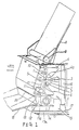
- FIG 1 shows the arrangement of an apparatus in accordance with one embodiment of the present invention.
- a cylindrical photosensitive member or drum 1 is rotatably mounted so as to be rotatable in the direction of an arrow A.
- a charging device 2 an optical signal generator 3 for irradiating the photosensitive member 1 with a light pattern in accordance with the image to be produced, a developing device 4 for developing a latent image on the photosensitive member 1, a transfer device 5 for transferring the developed image from the photosensitive member 1 to the sheet of paper, a cleaning device 6 for cleaning toner from the photosensitive member 1, and an erasing device 7 are disposed around the photosensitive member 1.
- a paper stacker 8, a paper feed roller 9 and paper register rollers 10 are disposed above the photosensitive member 1, while a fixing device 11 for fixing on the sheet of paper the developed image which has been transferred thereto, a paper guide plate 12, delivery rollers 13, an exhaust fan 14 and a power supply 15 are disposed below the photosensitive member 1.
- a control board 16 is disposed on the rear side of the body of the apparatus. The apparatus is provided with an outer casing 17.
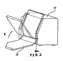
- a delivery tray 18 is, as shown in Figure 2, provided so as to be capable of being pivoted in the direction of an arrow B about a pivot axis 18a so that it can be accommodated on the outer side of the casing 17 when the apparatus is in an inoperative state.
- the casing 17 has a paper insertion opening 19 adjacent the top of the casing 17 and a paper discharge opening 20 which is adjacent to the bottom of the casing 17 and is at the front of the casing 17.
- the paper feed roller 9, the paper register rollers 10 and the delivery rollers 13 constitute transport means for causing the sheet of paper (not shown) to be transported along a paper transport path 21 from the paper insertion opening 19 to the paper discharge opening 20, the parts 1-7, 11 constituting electrophotographic means for imparting the image to the sheet of paper while the latter is on the paper transport path 21.
- the casing 17 has a base portion 17a which supports the apparatus and which is positioned below the paper transport path 21.
- the photosensitive member 1 has a surface layer which has photo-semiconductor characteristics such that it shows a relatively high electrical resistance in a dark place (i.e. the surface layer becomes an insulator), whereas, when light is applied thereto, the electrical resistance of the irradiated portion lowers (i.e. the irradiated portion becomes an electrical conductor).
- the charging device 2 generates a corona discharge when a high voltage, i.e. several kilovolts, is applied between a fine metal wire (not shown) and a ground electrode (not shown), thus causing a positive or negative electrical charge to be generated near the charging device 2.
- a high voltage i.e. several kilovolts
- the optical signal generator 3 is constituted by a device having a relatively short optical path, such as a liquid crystal shutter array or an LED array, and is adapted to convert electrical image information produced at the control board 16 into optical signals (ON and OFF signals in the form of light) and to output the converted signals. It should be noted that a laser scanner (not shown) may also be employed as the optical signal generator 3, although in such a case the optical path becomes relatively long.
- the ambient light is shut off by means of the outer casing 17, and when the inside of the outer casing 17 is dark, the photosensitive member 1 is constituted by an insulator.
- the photosensitive member 1 is rotated at a constant speed, the positive or negative electrical charge generated by means of the charging device 2 adheres to the surface of the photosensitive member 1 (i.e. the member 1 is electrically charged).
- the charged photosensitive member 1 is irradiated with light in accordance with the image information from the optical signal generator 3.
- the irradiated portion is changed to an electrical conductor and the charge on the surface of the irradiated portion is grounded.
- the surface of the photosensitive member 1 in this state has a portion on which a charge corresponding to the image information is present and a portion having no charge (i.e. a latent image portion is formed).
- the developing device 4 contains toner (not shown) which is charged positive or negative.
- the developing device 4 brings the toner into contact with the said latent image portion through a developing sleeve 4 a . Whether the toner is to be attached to a charged portion of the surface of the photosensitive member 1 or to the non-charged portion is determined in accordance with the polarity of the charge on the surface of the photosensitive member 1 and the polarity of the charged particles of the toner.
- the toner adheres to the non-charged portion of the photosensitive member 1, whereas, if the polarity of the charged particles of the toner is negative, the toner adheres to the charged portions of the surface of the photosensitive member 1.
- the charge on the surface of the photosensitive member 1 is negative, if the polarity of the charged particles of the toner is positive, the toner adheres to the charged portion of the surface of the photosensitive member 1, whereas, if the polarity of the charged particles of the tones is negative, the toner adheres to the non-charged portion of the surface of the photosensitive member 1.
- the uppermost one of the sheets of paper stored in the paper stacker 8 is fed by the action of the paper feed roller 9 to the paper register rollers 10 to stand by at this position.
- the register rollers 10 rotate in synchronism with the rotation of the photosensitive member 1 developed by the operation of the developing device 4 having the toner adhering to the surface thereof, and the paper is thereby advanced to an intermediate position between the photosensitive member 1 and the register rollers 10.
- the transfer device 5 has two constituent members, namely a fine metal wire (not shown) and a ground electrode (not shown) in the same way as the charging device 2 and is adapted to charge the rear side of the paper by means of positive or negative ions which are generated by a relatively high voltage applied between the two consitutuent members.
- the toner developed on the surface of the photosensitive member 1 is attracted to the obverse surface of the paper by means of the positive or negative charge on the reverse surface of the paper, thus effecting the transfer.
- the paper subjected to the transfer operation is passed through the area between fixing rollers of the fixing device 11 and, while doing so, the toner on the surface of the paper is fixed thereto.
- this embodiment adopts a fixing method employing a heated roller for the purpose of minimizing the size of the apparatus.
- a heat source such as an infra-red lamp is disposed in the centre of a roller 11 a , thereby effecting temperature control so that the surface temperature of the roller 11 a is maintained at a constant level.
- the surface temperature of the roller 11 a depends upon the kind of toner used, but it is generally set at from about 140°C to 200°C.
- the toner on the paper comes into contact with the surface of the roller 11 a and receives heat from the latter, thus causing a resin contained in the toner as a component thereof to be fused so as to penetrate the fibres of the paper.
- the fused toner is cooled and fixed to the surface of the paper at the time the paper is fed out from the area between the fixing rollers.
- the transfer device 5 is disposed on the horizontal line which passes through the centre of the photosensitive member 1 and on the front side of the image forming apparatus.
- the optical signal generator 3 is disposed on said horizontal line and on the rear side of the apparatus.
- the length of the optical path l ( Figure 3) needs to be about 300 mm at the minimum, which means that it is difficult to reduce the depth D of the image forming apparatus as shown in Figure 3. It should be noted that l in this embodiment is about 300 mm.
- an optical system employing a laser diode is provided with one reflecting portion (or mirror 19 b ) as shown in Figure 4, a polygon scanner 19 a which rotates at high speed must be disposed in such a manner that its longitudinal axis extends horizontally, which means that a very heavy load is imposed on a means for supporting the rotation of the polygon scanner 19 a and this makes it difficult to ensure that it has a long life.
- the light generated from the laser diode is reflected by the polygon scanner 19 a which is rotated at high speed and which transfers the latent image to the photosensitive member 1 by way of the mirror 19 b .
- a liquid crystal shutter array or an LED array (the optical path of which devices is 70 mm or less) is employed to constitute the optical signal generator 3, thereby allowing a reduction in the depth D of the image forming apparatus.
- the optical signal generator 3 can also be constituted by a laser scanner although the cost is relatively high.
- the paper passing through the fixing device 11 is discharged to the outside of the image forming apparatus by the action of the delivery rollers 13.
- the paper is discharged to the front side of the apparatus in such a manner that the printed surface thereof faces downwardly.
- the paper register rollers 10 which are defined by a pair of rollers and the fixing device 11 which is also defined by a pair of rollers are disposed in such a manner that the line which intersects the area of contact between the former pair of rollers and that between the latter pair of rollers (said line defining the paper transport path 21), extends substantially vertically, and the photosensitive member 1 is disposed so as to be in contact with said vertical line at the transfer position.
- the photosensitive member 1 after the completion of the transfer, has a slight amount of toner remaining on its surface, said toner having failed to be transferred.
- the remaining toner is scraped off by means of the cleaning device 6.
- the surface of the photosensitive member 1 is uniformly irradiated with light by means of the erasing device 7 in order to allow the charge to escape reliably from the surface of the photosensitive member 1 and to make the surface condition of the latter uniform.
- the exhaust fan 14 is disposed near and below the fixing device 11 to discharge the air heated by the power supply 15 and by the fixing device 11.
- the power supply 15 supplies electrical power to each of the units in the image forming apparatus. Since the power supply 15 includes a transformer (not shown) and other heavy members as its constituent elements, it is disposed in the lowermost part of the apparatus. In the case of an image forming apparatus having a relatively small bottom area and a relatively large height, it is very desirable to dispose the power supply 15 in the lowermost part of the apparatus.
- the control board 16 is arranged to control a signal to be sent to the optical signal generator 3, to interface the image forming apparatus with a host computer not shown, and to effect sequence control of each of the elements in the apparatus.
- the control board 16 since the control board 16 has a size which is approximately equal to the paper size A4, it is disposed on the rear side of the image forming apparatus.
- an image forming apparatus having a width W of 300 mm, a depth D of 170 mm and a height H of 260 mm was experimentally produced.
- the height H is greater than the depth D.
- the paper transport path 21 was not bent to a substantial degree and the greatest angle of bend was about 20 to 30° as described above. Thus, it was possible to print envelopes and the like without the occurrence of any jam and without the generation of wrinkles. In the experiments, a structure in which the paper transport path 21 was bent at about 90° was examined and almost no problem was found.
- the most preferable angle at which the paper transport path 21 may be bent is about 20° to 30° at the maximum, the preferred range of angles being from about 60° to about 80°.
- the paper transport path 21 may be arranged so as to extend substantially vertically as in the case of this embodiment, or may be such as to have a structure obtained by turning the arrangement of the prior art shown in Figure 13 upside down.
- a paper transport path 21 which extends substantially vertically as in the case of this embodiment, and it is very desirable, in order to realize this structure, to dispose the optical signal generator 3 so as to emit an optical signal toward the centre of the photosensitive member 1 from a position which is within a range of 60° around the horizontal line which passes through the centre of the photosensitive member 1. It is preferable for the optical signal generator 3 to emit an optical signal from a position which is substantially on said horizontal line. Further, it is very desirable to dispose the developing device 4 above the optical signal generator 4 from the viewpoint of the above-described structural features. It is preferable to dispose the developing device 4 within a range of 10° to 90° from said horizontal line. More specifically, it is preferable to dispose the developing sleeve 4 a at the lowermost portion of the developing device 4 with a view to realizing a structure which enables the toner to be most efficiently transported by means of gravity.
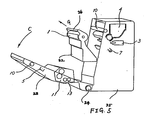
- the photosensitive member 1, the charging device 2 and the cleaning device 6 are formed as a unit to constitute a cartridge 22 which is adapted to be detachable with respect to the apparatus body, as shown in Figure 5 which illustrates the way in which the cartridge 22 is loaded or unloaded with a movable part 23 of the image forming apparatus opened.
- Figure 5 illustrates the same members as those shown in Figure 1 are denoted by the same reference numerals.
- the transfer device 5 and the fixing device 11 are rigidly secured to the inner side of a movable part 23 and constitute the movable part 23 as a whole.
- the movable part 23 is supported by a pivot shaft 24 mounted in an immovable part 25 of the image forming apparatus.
- the movable part 23 When the cartridge 22 is to be unloaded the movable part 23 is pivoted in the direction of an arrow C and the cartridge 22, which is guided and supported by a guide member (not shown) which is rigidly secured to the immovable part 25, is unloaded in the direction of an arrow G.
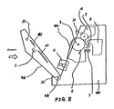
- the fixing device 11 is constituted by two roller sections 31 and 32 which include the rollers 11 and 11 a and resilient members, for example, springs 34, are provided so as to urge the roller sections 31 and 32 away from each other and thus urge them in the direction in which the nip pressure is cancelled.
- the movable part 23 becomes very heavy, and if the movable part 23 is opened carelessly, a harmful impact may be applied to the whole of the apparatus in addition to the impact to the abutment member 35 and the support shaft 24. There is also a risk that the apparatus will be forced to fall down or will be forced to collide with another object. The occurrence of such accidents is prevented by the action of a damping means 36 which enables the movable part 23 to be opened smoothly and slowly at a predetermined speed.
- the fixing device 11 on the immovable part 25 is provided with one of the register rollers 10 and with paper guides 40.
- the apparatus it is necessary to arrange the apparatus so that the cartridge 22 can be loaded from or unloaded toward the front side of the apparatus without being obstructed by the fixing device 11.
- the structure may be greatly simplified.
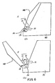
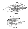
- the transfer device 5 may be provided on the cartridge 22, and may further be made detachable, as best shown in Figure 10(a2), or the transfer device 5 may be made pivotal, as in Figures 10(b1) and 10(b2) about either one or both of two regions where it is supported by the cartridge 22, thereby facilitating cleaning of the transfer device 5 and removal of jamming paper.
- Figure 10(b3) illustrates how the lower end of the transfer device 5 may be received in a catch 5 a in the cartridge 22.
- the cartridge 22 may have a flat bottom surface or may have a plurality of projections 41 to 44 provided on its bottom surface as shown in Figure 11. More specifically, the cartridge 22 may be arranged such that it is supported by at least three projections which define in combination a polygonal stable plane and the centre of gravity of the cartridge 22 is perpendicularly upwardly thereof. In such a case, it is possible to dispose the cartridge 22 on even a non-flat plane without any fear of the cartridge 22 oscillating unstably. Employment of rubber leg members to define the above-described projections improves the stability and prevents generation of noise. It is also possible to increase the degree of accuracy in the mounting of the cartridge 22 by employing the projections as positioning members when the cartridge 22 is loaded into the apparatus body.
- the position of the centre of gravity of the cartridge 22 changes as the amount of waste toner changes, but it is preferable to meet the above-described conditions concerning the centre of gravity irrespective of the amount of toner.
- the cartridge 22 may be loaded or unloaded using a handle 26 as shown in Figure 5.
- the handle 26 is defined by a member which is formed integrally with the casing of the cartridge 22 so as to project from the casing and extend in the direction of the axis of rotation of the photosensitive member 1.
- the handle 26 is formed at such a position that it is possible to draw out the cartridge 22 from the image forming apparatus and transport the cartridge 22 without any need to change its posture and shift it from one hand to the other.
- the user opens the movable part 23, draws out the cartridge 22 in the direction of the arrow G and then, for example, transports it to another place.
- the handle 26 Since the handle 26 is provided on the uppermost part of the cartridge 22 as viewed when it is loaded inside the apparatus body, there is apparently no fear that the posture of the cartridge 22 provided with such a handle 26 will be changed during the unloading operation. Accordingly, the waste toner which is collected within the cleaning device 6 provided below the photosensitive drum 1 is left as it is during the unloading operation and there is therefore no risk of the waste toner being moved to one side so as to scatter or leak out of the cartridge 22. Further, the cartridge 22 according to this embodiment has a bottom surface which is so shaped and a centre of gravity which is so positioned that the cartridge 22 will maintain the above-described posture without any change even when it is left outside the image forming apparatus for some reason.
- Toner has an angle of repose in the range from 40° to 50° with respect to the horizontal and when the angle of inclination exceeds this range, the toner flows. Accordingly, any change in posture of the cartridge 22 during the unloading operation and transportation, or when it is temporarily left outside the image forming apparatus, should be kept at a level which is less than the above-described angle of repose. It is desirable that any change in the posture of the cartridge 22 should be much smaller than the angle of repose of the toner.
- the cartridge 22 according to this embodiment is arranged as shown in Figure 12 which is a sectional view thereof.
- the image forming apparatus has a reduced bottom area and therefore occupies a minimized area on the top of a desk.
- the above-described embodiment has a depth D of about 170 mm and therefore, when this apparatus is placed on an ordinary desk having a depth of 700 mm and sheets of paper of A4 size are discharged from the front side of the apparatus, the sum total of the length of the paper, i.e., 300 mm, and the depth of the apparatus, i.e. 170 mm, is 470 mm, which means that a sufficiently large area is left on the top of the desk. Further, since paper is discharged from the front side of the apparatus, it is easy for the operator to handle the sheets of paper coming from the machine.
- the transfer device 5 is incorporated in the cartridge 22, it is unnecessary for the user to clean the transfer device (i.e. the transfer device is disposable).
- the embodiments of the present invention described above enable the transfer device to be readily cleaned in case of occurrence of any abnormal operation.
Landscapes
- Physics & Mathematics (AREA)
- General Physics & Mathematics (AREA)
- Engineering & Computer Science (AREA)
- Computer Vision & Pattern Recognition (AREA)
- Electrophotography Configuration And Component (AREA)
- Electrostatic Charge, Transfer And Separation In Electrography (AREA)
Description
- This invention concerns an apparatus for forming an image on a sheet of paper, the apparatus being of the type, shown for instance in EP-A-78,019, comprising a paper insertion region and a paper discharge region, transport means for causing the sheet of paper to be transported along a paper transport path from the paper insertion region to the paper discharge region, and electrophotographic means for imparting the image to the sheet of paper while the latter is on the paper transport path.
- Apparatus of the above-mentioned type may either be arranged for "face-up" or for "face down" delivery, in which the surface of the sheet of paper having the image thereon faces upwardly or downwardly respectively. Apparatus arranged for face-up delivery such, for example, as that disclosed in EP-A-78,019 reverses the paginal order of the sheets, whereas apparatus arranged for face-down delivery is liable to cause the paper to curl since it is turned back on itself, there is an increase in the rate of jamming due to an increase in the length of the paper transport path, the said transport means is complicated and expensive, and printing is slow.
- According, therefore, to the present invention there is provided an apparatus for forming an image from an original on a sheet of paper comprising a paper insertion region; a paper discharge region; transport means for causing the sheet of paper to be transported along a paper transport path from the paper insertion region to the paper discharge region; sheet receiving means for receiving sheets from the paper discharge region, electrophotographic means for imparting the image to the sheet of paper while the latter is on the paper transport path, the paper insertion region and the paper discharge region being disposed on vertically opposite sides respectively of the electrophotographic means; and support means which supports the apparatus and which is positioned below the paper transport path; the angle between the plane of the sheet of paper at any position on the paper transport path and its plane at the paper insertion region not exceeding 90°, characterised in that the apparatus is arranged such that a sheet of paper fed therethrough is discharged from the paper discharge region with its printed surface facing downwardly, whereby if a stack of sheets which has in operation been built up on the sheet receiving means is turned over, the page order of the image-bearing surfaces of the sheets in the stack is the same as that of the corresponding originals which were copied.
- The apparatus may be constituted by a desk-top apparatus.
- In the preferred embodiment of the present invention, the apparatus has a reduced production cost and is capable of printing thick paper, envelopes and the like using a face-down delivery mechanism alone without the need to provide a face-up delivery mechanism and associated switching means and with a reduced risk of causing a jam.
- It is preferably so designed that the fast print time (the period of time which begins at the time when a print command is given and which ends at the time when a printed sheet of paper has completely been discharged) is reduced by a large margin and the operability is improved.
- It is also preferably such as to have a reduced production cost and may be compact in size and light in weight. It is preferably so designed that any jam can readily be cleared even by an inexperienced user in a natural posture without any fear of his hands being stained and with no risk of the machine being damaged. It is also preferably such that the user can reliably exchange a cartridge employed in the apparatus in a natural posture, this being achieved by performing almost the same operation as a jam removing operation from the front side of the apparatus from which paper is discharged in normal use.
- The electrophotographic means preferably comprises a photosensitive member, an optical signal generator for irradiating the photosensitive member with a light pattern in accordance with the image to be produced, a developing device for developing a latent image on the photosensitive member, and a transfer device for transferring the developed image from the photosensitive member to the sheet of paper. Moreover, a fixing device may be provided for fixing on the sheet of paper the developed image which has been transferred thereto.
- The optical signal output from the optical signal generator preferably enters the photosensitive member at an angle not exceeding 60° to the horizontal line which passes through a central axis of the photosensitive member.
- The developing device is preferably disposed above an optical signal incident portion of the photosensitive member.
- The electrophotographic means may comprise a charging device for charging a portion of the photosensitive member and a cleaning device for cleaning toner from the photosensitive member.
- The transfer device may be disposed on one side of the photosensitive member, the optical signal generator is disposed on the opposite side of the photosensitive member, and the charging device and the cleaning device face the bottom of the photosensitive member.
- Moreover, the transfer device may be disposed above the bottom portion of the photosensitive member.
- The electrophotographic means may comprise a cartridge which is provided with at least two of the parts comprising the photosensitive member, the cleaning device and the charging device.
- The cartridge may carry the said transfer device and the latter may be detachable from the cartridge.
- The transfer device may be pivotally connected at one end thereof to the cartridge so that it can be moved pivotally about said end.
- Alternatively, the arrangement may be that the opposite ends of the transfer device are pivotally connected to and supported by the cartridge.
- The cleaning device may have a waste toner receptacle, the cleaning device having a flat bottom surface or at least three projections on its bottom surface which define a ground plane, the centre of gravity of the cartridge being within the ground plane.
- The cartridge may be provided with a handle by means of which the cartridge may be maintained in the same posture while being loaded into and out of the apparatus and while being transported. The cleaning device may be arranged to be supported in the cartridge by said handle in such a way that a first straight line which intersects the handle and the centre of gravity of the cartridge when there is no waste toner in said receptacle is disposed adjacent a second straight line which intersects the said handle and the centre of gravity of the cartridge when there is a substantial quantity of toner in the said receptacle.
- There may be paper feed means disposed above the photosensitive member and paper delivery means disposed below the photosensitive member.
- Preferably, the apparatus has a casing a lower front part of which has a tray portion which may be moved into and out of a position in which it is arranged to printed sheets of paper.
- The transfer device may be formed integrally with the cartridge, thereby eliminating the need to carry out maintenance such as cleaning of the transfer device and also enabling the transfer device to be readily moved away from the photosensitive member in order to facilitate, for example, removal of jamming paper. This construction allows the transfer device to be readily cleaned if it needs to be cleaned when trouble occurs.
- If the developing device is disposed above the photosensitive member included in the cartridge in order to arrange the electrophotographic means vertically, a movable part of the casing can be opened outwardly from the front side thereof, thus enabling cartridges to be exchanged and jammed paper to be removed from the opening provided between immovable and movable parts of the casing.
- The invention is illustrated, merely by way of example, in the accompanying drawings, in which:
- Figure 1 is a sectional view of one embodiment of an apparatus according to the present invention;
- Figure 2 is a perspective view which shows the external appearance of one embodiment of an apparatus according to the present invention in which a delivery tray can be accommodated on the outer side of the casing of the apparatus;
- Figure 3 shows one example of an apparatus according to the present invention in which a laser diode is employed as an optical signal generator;
- Figure 4 shows one example of an apparatus according to the present invention in which a reflecting mirror is employed in the laser optical path;
- Figure 5 shows a movable part of one embodiment of the present invention in its opened state and also shows the direction in which a cartridge is unloaded;
- Figures 6(a) and 6(b) show in combination the way in which the nip pressure applied by the rollers of a fixing device in one embodiment of the present invention is automatically cancelled by opening the movable part;
- Figures 7(a) and 7(b) show in combination the way in which the degree of opening of the movable part in one embodiment of the present invention is limited to a predetermined angle by an abutment member and, even when the movable part is in the fully opened position, the angle to which it is opened is regulated so that the position of centre of gravity thereof is not offset from the bottom of the apparatus;
- Figure 8 shows one embodiment of the present invention in which the fixing device is installed on the immovable part;
- Figures 9(a) and 9(b) show in combination one embodiment of the present invention in which a damping means is provided for preventing the movable part from gravitationally opening suddenly and in which the movable part is opened to such an extent that it comes into contact with the surface of the place on which the apparatus is installed;
- Figures 10(a₁), 10(a₂), 10(b₁), 10(b₂), 10(b₃) and 10(c₁), 10(c₂) show various examples of the arrangement of a cartridge of an apparatus according to the present invention;
- Figure 11 shows one example of a cartridge which may be used in an apparatus according to the present invention, the cartridge being provided with projections;
- Figure 12 is a sectional view showing the positional relationship between a handle and a cleaning device provided on the cartridge;
- Figure 13 shows a prior art apparatus in which paper is discharged in a face-up delivery manner; and
- Figure 14 shows another prior art apparatus in which paper is fed from the front side of the apparatus and is discharged onto the upper side thereof in a face-down delivery manner.
- Terms such as "right" and "left", as used in the description below, are to be understood to refer to directions as seen in the respective drawings.
- Figure 13 schematically shows the arrangement of a prior art electrophotographic image forming apparatus. In the apparatus of Figure 13, a
paper stacker 8 and adelivery tray 18 are disposed on the right- and left-hand sides, respectively, as viewed from the front side of the apparatus. A sheet of paper is fed from the right-hand side as viewed in Figure 13, passed through the inside of an image forming apparatus and discharged onto thetray 18 in such a manner that the surface of the sheet of paper having an image formed thereon faces upwardly. When the discharge of the paper is carried out in this way it is generally known as "face-up delivery". In such arrangement, the width W of the image forming apparatus needs to be about three times the length ℓ of the paper, and the depth D of the apparatus needs to be equal to the sum of the width w of the paper and some additional minimum length. - Figure 14 shows another prior art apparatus in which paper is discharged in such a manner that the image forming surface thereof faces downwardly. When the discharge of the paper is carried out in this way it is generally known as "face-down delivery". When the face-down delivery is adopted, output sheets of paper are stacked in the order,
page 1,page 2,page 3 ..., from the bottom toward the top of the stack of sheets. Therefore, when the stack of output sheets is turned upside down so that the image forming surface of the uppermost sheet can be seen, the uppermost sheet ispage 1 and the following sheets arepage 2,page 3..., which means that it is unnecessary to rearrange the stack of sheets in the paginal order. In the case of the face-up delivery, on the other hand,when the stack of output sheets is placed in the state wherein the image forming surface of the uppermost sheet of the stack can be seen, the uppermost sheet is the final page and the lowermost sheet ispage 1, which means that it is necessary to rearrange the stack of sheets in the paginal order. - In the prior art apparatus shown in Figure 14, the width W' of the image forming apparatus is the same as the depth D of the apparatus shown in Figure 13, whereas the depth D' of the apparatus shown in Figure 14 is about twice the length ℓ of the paper.
- Reference numerals shown in Figures 13 and 14 and not referred to above correspond to like numbered parts of Figures 1 and 2 which are described below.
- The arrangement shown in Figure 14, which is adopted to achieve face-down delivery, has the disadvantages that there is an increase in the degree to which the paper curls, since the paper is returned back, and that there is an increase in the rate of jamming due to an increase in the length of the paper transport path. In addition, since the paper transport mechanism is complicated, the production costs are raised and there is a considerable increase in the "first print time" (the period of time which begins at the time when a print command is given and which ends at the time when the first printed sheet of paper has been completely discharged from the machine body. The quality of the printing may be judged by the length of the first print time).
- Further, unlike the face-up delivery, the face-down delivery involves a structure in which a
paper transport path 21 is twice bent at approximately 90° in its course, which means that it is impossible to prevent thick paper, envelopes and the like from causing a jam or from becoming wrinkled. - In order to enable envelopes and the like to be printed without such problems, it is necesary to increase the radius of a circle defined by a bent portion of the
paper transport path 21 to about 5 cms, and this leads to a considerable increase in the size of the apparatus. - Accordingly, an apparatus which is stated to be capable of printing envelopes and the like is provided with a mechanism in which a paper path switching lever is provided immediately downstream of a
fixing device 11 so that paper is not bent but is discharged as it is in the face-up delivery manner, which means that the size of this type of apparatus is increased correspondingly and the number of required parts is also increased, resulting in a rise in the production cost. In addition, it is necessary to switch over the face-up and face-down delivery modes from one to the other according to need, and if the operator forgets to conduct this changeover operation, a jam may occur, and this may lead to a failure of the apparatus. - The prior art further involves the problem that it is complicated and difficult to exchange cartridges, which get used up, and the apparatus can only be installed in a position which gives free access to the relevant side of the apparatus which must be accessible to enable parts to be exchanged, and this requires an exceedingly large installation space. In addition, since a clamshell system is adopted in order to overcome jamming, there is a need to provide a strong spring for raising almost all the elements constituting a heavy electrophotographic system and an optical writing system, and the machine frame therefore needs to have great strength so that it is not deformed by the force from the strong spring, and this produces an increase in production costs. Further, it is necessary, when removing a cause of a paper jam, to conduct an operation in which the operator stoops down to look into the interior of the machine from an opening which is located at a relatively low position and looks like an open mouth of a shellfish, which is an awkward operation. In addition, since the inside of the apparatus cannot be seen very clearly, an essential member of the electrophotographic system may be damaged when the jammed paper is pulled out.
- The arrangement and features of an apparatus according to the present invention will therefore now be described hereinunder with reference to the accompanying drawings.
- Figure 1 shows the arrangement of an apparatus in accordance with one embodiment of the present invention.
- A cylindrical photosensitive member or
drum 1 is rotatably mounted so as to be rotatable in the direction of an arrow A. A chargingdevice 2, anoptical signal generator 3 for irradiating thephotosensitive member 1 with a light pattern in accordance with the image to be produced, a developingdevice 4 for developing a latent image on thephotosensitive member 1, atransfer device 5 for transferring the developed image from thephotosensitive member 1 to the sheet of paper, acleaning device 6 for cleaning toner from thephotosensitive member 1, and an erasingdevice 7 are disposed around thephotosensitive member 1. Apaper stacker 8, apaper feed roller 9 andpaper register rollers 10 are disposed above thephotosensitive member 1, while a fixingdevice 11 for fixing on the sheet of paper the developed image which has been transferred thereto, apaper guide plate 12,delivery rollers 13, anexhaust fan 14 and apower supply 15 are disposed below thephotosensitive member 1. Acontrol board 16 is disposed on the rear side of the body of the apparatus. The apparatus is provided with anouter casing 17. - A
delivery tray 18 is, as shown in Figure 2, provided so as to be capable of being pivoted in the direction of an arrow B about apivot axis 18a so that it can be accommodated on the outer side of thecasing 17 when the apparatus is in an inoperative state. - The
casing 17 has apaper insertion opening 19 adjacent the top of thecasing 17 and a paper discharge opening 20 which is adjacent to the bottom of thecasing 17 and is at the front of thecasing 17. Thepaper feed roller 9, thepaper register rollers 10 and thedelivery rollers 13 constitute transport means for causing the sheet of paper (not shown) to be transported along apaper transport path 21 from thepaper insertion opening 19 to thepaper discharge opening 20, the parts 1-7, 11 constituting electrophotographic means for imparting the image to the sheet of paper while the latter is on thepaper transport path 21. Thecasing 17 has abase portion 17a which supports the apparatus and which is positioned below thepaper transport path 21. - The image forming process carried out by the apparatus according to the present invention will be explained below.
- The
photosensitive member 1 has a surface layer which has photo-semiconductor characteristics such that it shows a relatively high electrical resistance in a dark place (i.e. the surface layer becomes an insulator), whereas, when light is applied thereto, the electrical resistance of the irradiated portion lowers (i.e. the irradiated portion becomes an electrical conductor). - The charging
device 2 generates a corona discharge when a high voltage, i.e. several kilovolts, is applied between a fine metal wire (not shown) and a ground electrode (not shown), thus causing a positive or negative electrical charge to be generated near the chargingdevice 2. - The
optical signal generator 3 is constituted by a device having a relatively short optical path, such as a liquid crystal shutter array or an LED array, and is adapted to convert electrical image information produced at thecontrol board 16 into optical signals (ON and OFF signals in the form of light) and to output the converted signals. It should be noted that a laser scanner (not shown) may also be employed as theoptical signal generator 3, although in such a case the optical path becomes relatively long. - The ambient light is shut off by means of the
outer casing 17, and when the inside of theouter casing 17 is dark, thephotosensitive member 1 is constituted by an insulator. When, in this state, thephotosensitive member 1 is rotated at a constant speed, the positive or negative electrical charge generated by means of thecharging device 2 adheres to the surface of the photosensitive member 1 (i.e. themember 1 is electrically charged). The chargedphotosensitive member 1 is irradiated with light in accordance with the image information from theoptical signal generator 3. In consequence, the irradiated portion is changed to an electrical conductor and the charge on the surface of the irradiated portion is grounded. More specifically, the surface of thephotosensitive member 1 in this state has a portion on which a charge corresponding to the image information is present and a portion having no charge (i.e. a latent image portion is formed). - The developing
device 4 contains toner (not shown) which is charged positive or negative. The developingdevice 4 brings the toner into contact with the said latent image portion through a developingsleeve 4a. Whether the toner is to be attached to a charged portion of the surface of thephotosensitive member 1 or to the non-charged portion is determined in accordance with the polarity of the charge on the surface of thephotosensitive member 1 and the polarity of the charged particles of the toner. More specifically, when the charge on the surface of thephotosensitive member 1 is positive, if the polarity of charged particles of the toner is positive, the toner adheres to the non-charged portion of thephotosensitive member 1, whereas, if the polarity of the charged particles of the toner is negative, the toner adheres to the charged portions of the surface of thephotosensitive member 1. On the other hand, when the charge on the surface of thephotosensitive member 1 is negative, if the polarity of the charged particles of the toner is positive, the toner adheres to the charged portion of the surface of thephotosensitive member 1, whereas, if the polarity of the charged particles of the tones is negative, the toner adheres to the non-charged portion of the surface of thephotosensitive member 1. - The uppermost one of the sheets of paper stored in the
paper stacker 8 is fed by the action of thepaper feed roller 9 to thepaper register rollers 10 to stand by at this position. - The
register rollers 10 rotate in synchronism with the rotation of thephotosensitive member 1 developed by the operation of the developingdevice 4 having the toner adhering to the surface thereof, and the paper is thereby advanced to an intermediate position between thephotosensitive member 1 and theregister rollers 10. - The
transfer device 5 has two constituent members, namely a fine metal wire (not shown) and a ground electrode (not shown) in the same way as thecharging device 2 and is adapted to charge the rear side of the paper by means of positive or negative ions which are generated by a relatively high voltage applied between the two consitutuent members. The toner developed on the surface of thephotosensitive member 1 is attracted to the obverse surface of the paper by means of the positive or negative charge on the reverse surface of the paper, thus effecting the transfer. The paper subjected to the transfer operation is passed through the area between fixing rollers of the fixingdevice 11 and, while doing so, the toner on the surface of the paper is fixed thereto. Although there are known fixing methods employing heat and pressure rollers, respectively, this embodiment adopts a fixing method employing a heated roller for the purpose of minimizing the size of the apparatus. A heat source such as an infra-red lamp is disposed in the centre of aroller 11a, thereby effecting temperature control so that the surface temperature of theroller 11a is maintained at a constant level. The surface temperature of theroller 11a depends upon the kind of toner used, but it is generally set at from about 140°C to 200°C. The toner on the paper comes into contact with the surface of theroller 11a and receives heat from the latter, thus causing a resin contained in the toner as a component thereof to be fused so as to penetrate the fibres of the paper. The fused toner is cooled and fixed to the surface of the paper at the time the paper is fed out from the area between the fixing rollers. - In this embodiment, the
transfer device 5 is disposed on the horizontal line which passes through the centre of thephotosensitive member 1 and on the front side of the image forming apparatus. Thus thetransfer device 5 is disposed above the bottom portion of thephotosensitive member 1. Theoptical signal generator 3 is disposed on said horizontal line and on the rear side of the apparatus. When the image forming apparatus is used for a long period of time, paper dust and toner accumulate inside the apparatus, and the amount of accummulated dust and toner is largest at the gravitationally lower portion, that is, the lower portion of the apparatus. If toner or paper dust adheres to thetransfer device 5, a corona discharge may not occur in a normal state when a high voltage is applied; in such a case, transfer cannot satisfactorily be effected. Any toner or paper dust adhering to theoptical signal generator 3 blocks the passage of light and thus prevents thephotosensitive member 1 from becoming electrically conductive, so that the charge on the surface will not escape sufficiently. - To solve these problems, the disposition of the
transfer device 5 and theoptical signal generator 3 in the lower portion inside the apparatus is avoided in this embodiment. - When an optical system employing a laser diode (not shown) is adapted as the
optical signal generator 3, the length of the optical path ℓ (Figure 3) needs to be about 300 mm at the minimum, which means that it is difficult to reduce the depth D of the image forming apparatus as shown in Figure 3. It should be noted that ℓ in this embodiment is about 300 mm. If in order to minimize the depth D, an optical system employing a laser diode is provided with one reflecting portion (or mirror 19b) as shown in Figure 4, apolygon scanner 19a which rotates at high speed must be disposed in such a manner that its longitudinal axis extends horizontally, which means that a very heavy load is imposed on a means for supporting the rotation of thepolygon scanner 19a and this makes it difficult to ensure that it has a long life. The light generated from the laser diode is reflected by thepolygon scanner 19a which is rotated at high speed and which transfers the latent image to thephotosensitive member 1 by way of the mirror 19b. In this embodiment, a liquid crystal shutter array or an LED array (the optical path of which devices is 70 mm or less) is employed to constitute theoptical signal generator 3, thereby allowing a reduction in the depth D of the image forming apparatus. However, if a reflecting mirror is additionally provided, theoptical signal generator 3 can also be constituted by a laser scanner although the cost is relatively high. - The paper passing through the fixing
device 11 is discharged to the outside of the image forming apparatus by the action of thedelivery rollers 13. In this embodiment, the paper is discharged to the front side of the apparatus in such a manner that the printed surface thereof faces downwardly. Further, in this embodiment thepaper register rollers 10 which are defined by a pair of rollers and the fixingdevice 11 which is also defined by a pair of rollers are disposed in such a manner that the line which intersects the area of contact between the former pair of rollers and that between the latter pair of rollers (said line defining the paper transport path 21), extends substantially vertically, and thephotosensitive member 1 is disposed so as to be in contact with said vertical line at the transfer position. - The
photosensitive member 1, after the completion of the transfer, has a slight amount of toner remaining on its surface, said toner having failed to be transferred. The remaining toner is scraped off by means of thecleaning device 6. - Further, the surface of the
photosensitive member 1 is uniformly irradiated with light by means of the erasingdevice 7 in order to allow the charge to escape reliably from the surface of thephotosensitive member 1 and to make the surface condition of the latter uniform. - The
exhaust fan 14 is disposed near and below the fixingdevice 11 to discharge the air heated by thepower supply 15 and by the fixingdevice 11. - The
power supply 15 supplies electrical power to each of the units in the image forming apparatus. Since thepower supply 15 includes a transformer (not shown) and other heavy members as its constituent elements, it is disposed in the lowermost part of the apparatus. In the case of an image forming apparatus having a relatively small bottom area and a relatively large height, it is very desirable to dispose thepower supply 15 in the lowermost part of the apparatus. - The
control board 16 is arranged to control a signal to be sent to theoptical signal generator 3, to interface the image forming apparatus with a host computer not shown, and to effect sequence control of each of the elements in the apparatus. In this embodiment, since thecontrol board 16 has a size which is approximately equal to the paper size A4, it is disposed on the rear side of the image forming apparatus. - With the above-described contents, an image forming apparatus having a width W of 300 mm, a depth D of 170 mm and a height H of 260 mm was experimentally produced. Thus the height H is greater than the depth D. The
paper transport path 21 was not bent to a substantial degree and the greatest angle of bend was about 20 to 30° as described above. Thus, it was possible to print envelopes and the like without the occurrence of any jam and without the generation of wrinkles. In the experiments, a structure in which thepaper transport path 21 was bent at about 90° was examined and almost no problem was found. - However, when the
paper transport path 21 was bent at 120° or more, problems such as jamming and wrinkles occurred considerably in the case of certain kinds of paper, and when the angle of bend exceeded 180°, a relatively large number of different kinds of envelope became wrinkled almost every time they were printed. - Thus, the most preferable angle at which the
paper transport path 21 may be bent is about 20° to 30° at the maximum, the preferred range of angles being from about 60° to about 80°. - In the case where the apparatus is arranged so as to minimize the degree to which the
paper transport path 21 is bent as described above and is also arranged to employ face-down delivery, thepaper transport path 21 may be arranged so as to extend substantially vertically as in the case of this embodiment, or may be such as to have a structure obtained by turning the arrangement of the prior art shown in Figure 13 upside down. In the latter case, there are problems such as an increase in the amount of toner adhering to thecharging device 2 and to theoptical signal generator 3 due to the gravity drop, complication of the toner transport mechanism of the developingdevice 4, difficulty in employing a blade system which is suitable for reducing the size of thecleaning device 6, and damage to the image caused by the contact of the toner which has not yet been fixed with thepaper transport path 21 due to the fact that the printed surface of the paper faces upwardly In addition, the size of the apparatus is undesirably increased in the same way as in the case of the prior art shown in Figure 13. - Accordingly, it is preferable to provide a
paper transport path 21 which extends substantially vertically as in the case of this embodiment, and it is very desirable, in order to realize this structure, to dispose theoptical signal generator 3 so as to emit an optical signal toward the centre of thephotosensitive member 1 from a position which is within a range of 60° around the horizontal line which passes through the centre of thephotosensitive member 1. It is preferable for theoptical signal generator 3 to emit an optical signal from a position which is substantially on said horizontal line. Further, it is very desirable to dispose the developingdevice 4 above theoptical signal generator 4 from the viewpoint of the above-described structural features. It is preferable to dispose the developingdevice 4 within a range of 10° to 90° from said horizontal line. More specifically, it is preferable to dispose the developingsleeve 4a at the lowermost portion of the developingdevice 4 with a view to realizing a structure which enables the toner to be most efficiently transported by means of gravity. - When this embodiment was experimentally run at a print speed of 8 ppm. the fast print time was able to be shortened to only 12 seconds, whereas the fast print time in the prior art apparatus shown in Figure 14 is generally 30 to 40 seconds because of a relatively long paper transport path.
- In this embodiment, among the process elements, the
photosensitive member 1, the chargingdevice 2 and thecleaning device 6 are formed as a unit to constitute acartridge 22 which is adapted to be detachable with respect to the apparatus body, as shown in Figure 5 which illustrates the way in which thecartridge 22 is loaded or unloaded with amovable part 23 of the image forming apparatus opened. In Figure 5, the same members as those shown in Figure 1 are denoted by the same reference numerals. Thetransfer device 5 and the fixingdevice 11 are rigidly secured to the inner side of amovable part 23 and constitute themovable part 23 as a whole. Themovable part 23 is supported by apivot shaft 24 mounted in animmovable part 25 of the image forming apparatus. When thecartridge 22 is to be unloaded themovable part 23 is pivoted in the direction of an arrow C and thecartridge 22, which is guided and supported by a guide member (not shown) which is rigidly secured to theimmovable part 25, is unloaded in the direction of an arrow G. - As shown in Figures 6(a) and 6(b), the fixing
device 11 is constituted by tworoller sections rollers roller sections - Accordingly, when the
movable part 23 is opened, the nip pressure is cancelled, whereas, when it is closed, theroller section 32 is pressed by anabutment member 33, and a normal nip pressure for fixing is thus obtained. - When the
movable part 23 is opened, the centre of gravity is, as a matter of course, moved toward the front side of the apparatus, and in the worst case the apparatus may fall down toward the front side. However, in the embodiment illustrated in Figures 7(a) and 7(b), anabutment member 35 is provided so that themovable part 23 can be opened only to an angle 0 beyond which the position of the centre of gravity is no longer within the bottom of the apparatus, thereby making it possible to prevent the apparatus from falling down. - When, for example, the fixing
device 11 is provided on themovable part 23, themovable part 23 becomes very heavy, and if themovable part 23 is opened carelessly, a harmful impact may be applied to the whole of the apparatus in addition to the impact to theabutment member 35 and thesupport shaft 24. There is also a risk that the apparatus will be forced to fall down or will be forced to collide with another object. The occurrence of such accidents is prevented by the action of a damping means 36 which enables themovable part 23 to be opened smoothly and slowly at a predetermined speed. - It is also effective practice to provide the fixing
device 11 on theimmovable part 25 as shown in Figure 8 for the purpose of facilitating removal of a jam caused by paper passing through the fixingdevice 11. As shown in Figure 8, themovable part 23 is provided with one of theregister rollers 10 and with paper guides 40. In such a case, it is necessary to arrange the apparatus so that thecartridge 22 can be loaded from or unloaded toward the front side of the apparatus without being obstructed by the fixingdevice 11. In this arrangement, particularly, as shown in Figures 9(a), 9(b), since no heavy member is provided on themovable part 23, the structure may be greatly simplified. That is to say, it may be possible to omit theabutment member 35 and the damping means 36 and allow themovable part 23 to be opened until it comes into contact with the surface of the place on which the apparatus is installed. However, employment of the damping means 36 of course enables themovable part 23 to be opened and closed even more smoothly. - Referring next to Figures 10(a) to 10(C2), the
transfer device 5 may be provided on thecartridge 22, and may further be made detachable, as best shown in Figure 10(a₂), or thetransfer device 5 may be made pivotal, as in Figures 10(b₁) and 10(b₂) about either one or both of two regions where it is supported by thecartridge 22, thereby facilitating cleaning of thetransfer device 5 and removal of jamming paper. Figure 10(b₃) illustrates how the lower end of thetransfer device 5 may be received in a catch 5a in thecartridge 22. - The
cartridge 22 may have a flat bottom surface or may have a plurality ofprojections 41 to 44 provided on its bottom surface as shown in Figure 11. More specifically, thecartridge 22 may be arranged such that it is supported by at least three projections which define in combination a polygonal stable plane and the centre of gravity of thecartridge 22 is perpendicularly upwardly thereof. In such a case, it is possible to dispose thecartridge 22 on even a non-flat plane without any fear of thecartridge 22 oscillating unstably. Employment of rubber leg members to define the above-described projections improves the stability and prevents generation of noise. It is also possible to increase the degree of accuracy in the mounting of thecartridge 22 by employing the projections as positioning members when thecartridge 22 is loaded into the apparatus body. - It should be noted that the position of the centre of gravity of the
cartridge 22 changes as the amount of waste toner changes, but it is preferable to meet the above-described conditions concerning the centre of gravity irrespective of the amount of toner. - The
cartridge 22 may be loaded or unloaded using ahandle 26 as shown in Figure 5. Thehandle 26 is defined by a member which is formed integrally with the casing of thecartridge 22 so as to project from the casing and extend in the direction of the axis of rotation of thephotosensitive member 1. Thehandle 26 is formed at such a position that it is possible to draw out thecartridge 22 from the image forming apparatus and transport thecartridge 22 without any need to change its posture and shift it from one hand to the other. In other words, when thecartridge 22 is to be unloaded, the user opens themovable part 23, draws out thecartridge 22 in the direction of the arrow G and then, for example, transports it to another place. Since thehandle 26 is provided on the uppermost part of thecartridge 22 as viewed when it is loaded inside the apparatus body, there is apparently no fear that the posture of thecartridge 22 provided with such ahandle 26 will be changed during the unloading operation. Accordingly, the waste toner which is collected within thecleaning device 6 provided below thephotosensitive drum 1 is left as it is during the unloading operation and there is therefore no risk of the waste toner being moved to one side so as to scatter or leak out of thecartridge 22. Further, thecartridge 22 according to this embodiment has a bottom surface which is so shaped and a centre of gravity which is so positioned that thecartridge 22 will maintain the above-described posture without any change even when it is left outside the image forming apparatus for some reason. - Toner has an angle of repose in the range from 40° to 50° with respect to the horizontal and when the angle of inclination exceeds this range, the toner flows. Accordingly, any change in posture of the
cartridge 22 during the unloading operation and transportation, or when it is temporarily left outside the image forming apparatus, should be kept at a level which is less than the above-described angle of repose. It is desirable that any change in the posture of thecartridge 22 should be much smaller than the angle of repose of the toner. In order to achieve this, thecartridge 22 according to this embodiment is arranged as shown in Figure 12 which is a sectional view thereof. More specifically, when thecartridge 22 has not yet been used, no waste toner is collected in awaste toner box 50 provided inside thecleaning device 6 and the centre of gravity of thecartridge 22 is therefore at the point E, so that the point E and thehandle 26 are connected together by the straight line EH. As thecartridge 22 is used, waste toner is collected in thewaste toner box 50, resulting in the centre of gravity of thecartridge 22 moving to the point F, thehandle 26 and the point F being connected by the straight line FH. Thecleaning device 6 is, however, disposed at such a position that the straight lines EH and FH are adjacent to each other, thereby preventing, as much as possible, an undesirable degree of inclination of thecartridge 22 during its use. - As has been described above, the image forming apparatus has a reduced bottom area and therefore occupies a minimized area on the top of a desk. In particular, the above-described embodiment has a depth D of about 170 mm and therefore, when this apparatus is placed on an ordinary desk having a depth of 700 mm and sheets of paper of A4 size are discharged from the front side of the apparatus, the sum total of the length of the paper, i.e., 300 mm, and the depth of the apparatus, i.e. 170 mm, is 470 mm, which means that a sufficiently large area is left on the top of the desk. Further, since paper is discharged from the front side of the apparatus, it is easy for the operator to handle the sheets of paper coming from the machine. The arrangement wherein paper is inserted from the upper side of the apparatus and discharged from the front side thereof enables the face-down delivery system to be achieved with a paper transport path which is much simpler than that of the prior art. Accordingly, envelopes and the like can be printed without the need to additionally provide a face-up delivery mechanism and its associated switching means and with substantially reduced problems such as jamming and the generation of wrinkles.
- In addition, it is possible, according to this embodiment, to shorten the fast-print time to 12 seconds in the case of paper of A4 size, whereas the fast-print time of conventional 8 ppm machines is 25 to 30 seconds.
- It is possible for the operator to readily exchange cartridges and to remove jamming paper in a natural posture and also possible for him to see his hand during such an operation. There is therefore no fear of an electrophotographic process member being accidentally damaged.
- Since exchange of cartridges is carried out from the front side of the apparatus, there is no need to provide any free space for this purpose as a part of the installation space, which has heretofore been required for the prior art apparatus wherein exchange of cartridges is conducted from one lateral side of the apparatus.
- Although the prior art which adopts the clamshell system in order to cancel jamming needs a strong spring for supporting a movable part having a weight of several tens of kilograms in close proximity with the support point and also needs a high-strength frame for preventing deformation, the embodiments of the present invention described above eliminate the need to provide such members.
- Further, since the
transfer device 5 is incorporated in thecartridge 22, it is unnecessary for the user to clean the transfer device (i.e. the transfer device is disposable). The embodiments of the present invention described above enable the transfer device to be readily cleaned in case of occurrence of any abnormal operation. - It is possible for the user to readily load and unload the cartridge by holding the handle provided thereon and by placing it on the top of a desk or the like with ease and without any fear of waste toner collected therein moving to one side to fall.
Claims (18)
- Apparatus for forming an image from an original on a sheet of paper comprising a paper insertion region (19); a paper discharge region (20); transport means (9,10,13) for causing the sheet of paper to be transported along a paper transport path (21) from the paper insertion region (19) to the paper discharge region (20); sheet receiving means (18) for receiving sheets from the paper discharge region (20); electrophotographic means (1-7,11) for imparting the image to the sheet of paper while the latter is on the paper transport path (21), the paper insertion region (19) and the paper discharge region (20) being disposed on vertically opposite sides respectively of the electrophotographic means (1-7,11); and support means (17a) which supports the apparatus and which is positioned below the paper transport path (21); the angle between the plane of the sheet of paper at any position on the paper transport path (21) and its plane at the paper insertion region (19) not exceeding 90°, characterised in that the apparatus is arranged such that a sheet of paper fed therethrough is discharged from the paper discharge region (20) with its printed surface facing downwardly, whereby if a stack of sheets which has in operation been built up on the sheet receiving means (18) is turned over,the page order of the image-bearing surfaces of the sheets in the stack is the same as that of the corresponding originals which were copied.
- Apparatus as claimed in claim 1 characterised in that the electrophotographic means (1-7, 11) comprises a photosensitive member (1), an optical signal generator (3) for irradiating the photosensitive member (1) with a light pattern in accordance with the image to be produced, a developing device (4) for developing a latent image on the photosensitive member (1), and a transfer device (5) for transferring the developed image from the photosensitive member (1) to the sheet of paper.
- Apparatus as claimed in claim 2 characterised in that a fixing device (11) is provided for fixing on the sheet of paper the developed image which has been transferred thereto.
- Apparatus as claimed in claim 2 or 3 characterised in that the optical signal output from the optical signal generator (3) enters the photosensitive member (1) at an angle not exceeding 60° to the horizontal line which passes through a central axis of the photosensitive member (1).
- Apparatus as claimed in any of claims 2-4 characterised in that the developing device (4) is disposed above an optical signal incident portion of the photosensitive member (1).
- Apparatus as claimed in any of claims 2-5 characterised in that the electrophotographic means (1-7,11) comprise a charging device (2) for charging a portion of the photosensitive member (1) and a cleaning device (6) for cleaning toner from the photosensitive member (1).
- Apparatus as claimed in claim 6 characterised in that the transfer device (5) is disposed on one side of the photosensitive member (1), the optical signal generator (3) is disposed on the opposite side of the photosensitive member (1), and the charging device (2) and the cleaning device (6) face the bottom of the photosensitive member (1).
- Apparatus as claimed in any of claims 2-7 characterised in that the transfer device (5) is disposed above the bottom portion of the photosensitive member (1).
- Apparatus as claimed in claim 6 or 7 characterised in that the electrophotographic means (1-7,11) comprises a cartridge (22) which is provided with at least two of the parts comprising the photosensitive member (1), the cleaning device (6) and the charging device (2).
- Apparatus as claimed in claim 9 characterised in that the cartridge (22) carries the said transfer device (5).
- Apparatus as claimed in claim 10 characterised in that the transfer device (5) is detachable from the cartridge (22).
- Apparatus as claimed in claim 10 or 11 characterised in that the transfer device (5) is pivotally connected at one end thereof to the cartridge (22) so that it can be moved pivotally about said end.
- Apparatus as claimed in claim 10 or 11 characterised in that the opposite ends of the transfer device (5) are pivotally connected to and supported by the cartridge (22).
- Apparatus as claimed in claim 6 or in any claim appendent thereto characterised in that the cleaning device (6) has a waste toner receptacle (50), the cleaning device (6) having a flat bottom surface or at least three projections (41-44) on its bottom surface which define a ground plane, the centre of gravity of the cartridge (22) being within the ground plane.
- Apparatus as claimed in any of claims 9-14 characterised in that the cartridge (22) is provided with a handle (26) by means of which the cartridge (22) may be maintained in the same posture while being loaded into and out of the apparatus and while being transported.
- Apparatus as claimed in claim 15 characterised in that the cleaning device (6) is arranged to be supported in the cartridge (22) by said handle (26) in such a way that a first straight line (EH) which intersects the handle (26) and the centre of gravity of the cartridge (22) when there is no waste toner in said receptacle (50) is disposed adjacent a second straight line (FH) which intersects the said handle (26) and the centre of gravity of the cartridge (22) when there is a substantial quantity of toner in the said receptacle (50).
- Apparatus as claimed in any of claims 2-16 characterised in that there are paper feed means (10) disposed above the photosensitive member (1) and paper delivery means (13) disposed below the photosensitive member (1).
- Apparatus as claimed in any preceding claim characterised in that the apparatus has a casing (17) a lower front part of which has a tray portion (18) which moveable into and out of a position in which it is arranged to receive printed sheets of paper.
Priority Applications (2)
| Application Number | Priority Date | Filing Date | Title |
|---|---|---|---|
| EP91201876A EP0460773B1 (en) | 1986-04-04 | 1987-04-01 | Apparatus for forming an image on a record medium |
| EP91201875A EP0460772B1 (en) | 1986-04-04 | 1987-04-01 | Apparatus for forming an image on a record medium |
Applications Claiming Priority (8)
| Application Number | Priority Date | Filing Date | Title |
|---|---|---|---|
| JP77804/86 | 1986-04-04 | ||
| JP61077804A JPS62234170A (en) | 1986-04-04 | 1986-04-04 | Image forming device |
| JP61159244A JPS6315264A (en) | 1986-07-07 | 1986-07-07 | Image forming device |
| JP159244/86 | 1986-07-07 | ||
| JP61159246A JPS6317746A (en) | 1986-07-07 | 1986-07-07 | Image forming device |
| JP61159239A JPS6314168A (en) | 1986-07-07 | 1986-07-07 | Processing unit |
| JP159246/86 | 1986-07-07 | ||
| JP159239/86 | 1986-07-07 |
Related Child Applications (3)
| Application Number | Title | Priority Date | Filing Date |
|---|---|---|---|
| EP91201877.7 Division-Into | 1987-04-01 | ||
| EP91201875.1 Division-Into | 1987-04-01 | ||
| EP91201876.9 Division-Into | 1987-04-01 |
Publications (3)
| Publication Number | Publication Date |
|---|---|
| EP0240337A2 EP0240337A2 (en) | 1987-10-07 |
| EP0240337A3 EP0240337A3 (en) | 1988-07-27 |
| EP0240337B1 true EP0240337B1 (en) | 1993-02-24 |
Family
ID=27466105
Family Applications (6)
| Application Number | Title | Priority Date | Filing Date |
|---|---|---|---|
| EP93110199A Withdrawn EP0562647A2 (en) | 1986-04-04 | 1987-04-01 | Apparatus for forming an image on a record medium |
| EP91201876A Revoked EP0460773B1 (en) | 1986-04-04 | 1987-04-01 | Apparatus for forming an image on a record medium |
| EP91201875A Revoked EP0460772B1 (en) | 1986-04-04 | 1987-04-01 | Apparatus for forming an image on a record medium |
| EP19910201877 Withdrawn EP0453058A3 (en) | 1986-04-04 | 1987-04-01 | Apparatus for forming an image on a record medium |
| EP93110200A Revoked EP0562648B1 (en) | 1986-04-04 | 1987-04-01 | Apparatus for forming an image on a record medium |
| EP87302839A Expired - Lifetime EP0240337B1 (en) | 1986-04-04 | 1987-04-01 | Apparatus for forming an image on a sheet of paper |
Family Applications Before (5)
| Application Number | Title | Priority Date | Filing Date |
|---|---|---|---|
| EP93110199A Withdrawn EP0562647A2 (en) | 1986-04-04 | 1987-04-01 | Apparatus for forming an image on a record medium |
| EP91201876A Revoked EP0460773B1 (en) | 1986-04-04 | 1987-04-01 | Apparatus for forming an image on a record medium |
| EP91201875A Revoked EP0460772B1 (en) | 1986-04-04 | 1987-04-01 | Apparatus for forming an image on a record medium |
| EP19910201877 Withdrawn EP0453058A3 (en) | 1986-04-04 | 1987-04-01 | Apparatus for forming an image on a record medium |
| EP93110200A Revoked EP0562648B1 (en) | 1986-04-04 | 1987-04-01 | Apparatus for forming an image on a record medium |
Country Status (4)
| Country | Link |
|---|---|
| US (2) | US4754293A (en) |
| EP (6) | EP0562647A2 (en) |
| DE (4) | DE3750962T2 (en) |
| HK (3) | HK117895A (en) |
Families Citing this family (43)
| Publication number | Priority date | Publication date | Assignee | Title |
|---|---|---|---|---|
| JPH0844128A (en) * | 1994-07-28 | 1996-02-16 | Sharp Corp | Paper feeding and ejecting device for image forming device |
| US4868599A (en) * | 1986-06-02 | 1989-09-19 | Seiko Epson Corporation | Device and method for storing toner waste |
| EP0285139B1 (en) * | 1987-03-31 | 1995-10-11 | Canon Kabushiki Kaisha | An image forming apparatus |
| US5247316A (en) * | 1987-03-31 | 1993-09-21 | Canon Kabushiki Kaisha | Laser beam printer having three-point support system |
| CA1324912C (en) * | 1987-09-30 | 1993-12-07 | Sigeki Sakakura | Printer |
| US4804982A (en) * | 1988-04-29 | 1989-02-14 | Polaroid Corporation | Printer having reversible driving mechanism |
| CA1327831C (en) * | 1988-05-25 | 1994-03-15 | Shigeki Sakakura | Image-forming apparatus |
| US4941002A (en) * | 1988-08-31 | 1990-07-10 | Seiko Epson Corporation | Page printer |
| US4945364A (en) * | 1988-09-07 | 1990-07-31 | Seiko Epson Corporation | Page printer |
| US5245357A (en) * | 1988-09-07 | 1993-09-14 | Seiko Epson Corporation | Page printer |
| JPH0292569A (en) * | 1988-09-29 | 1990-04-03 | Seiko Epson Corp | Page printer |
| US5253013A (en) * | 1988-10-17 | 1993-10-12 | Asahi Kogaku Kogyo Kabushiki Kaisha | Image recording apparatus having releasable fixing device |
| EP0392529B1 (en) * | 1989-04-14 | 1994-12-14 | Seiko Epson Corporation | Electrophotographic recording apparatus |
| US5141222A (en) * | 1989-05-26 | 1992-08-25 | Seiko Epson Corporation | Process including multiple sheet discharge printer using electrophotographic receivers with a pivotal sorter guide |
| US5140369A (en) * | 1989-11-15 | 1992-08-18 | Konica Corporation | Color image forming apparatus having a process cartridge containing a belt shaped image carrier, toner replenishing means and detachable paper cartridge |
| JPH03174549A (en) * | 1989-12-04 | 1991-07-29 | Ricoh Co Ltd | Electrophotographic recording device |
| JP2784679B2 (en) * | 1990-03-20 | 1998-08-06 | コニカ株式会社 | Image forming device |
| JPH0473666A (en) * | 1990-07-12 | 1992-03-09 | Minolta Camera Co Ltd | Image forming device |
| KR930011661B1 (en) * | 1990-10-25 | 1993-12-16 | 현대전자산업 주식회사 | Laser beam printer without paper supply cassette |
| JP2576307B2 (en) * | 1991-04-30 | 1997-01-29 | 富士ゼロックス株式会社 | Image forming device |
| US5160964A (en) * | 1991-06-28 | 1992-11-03 | Matsushita Electric Industrial Co., Ltd. | Image recording apparatus occupying a minimum amount of space |
| DE69219539T2 (en) * | 1991-08-02 | 1997-12-18 | Minolta Camera Kk | Electrophotographic imaging device with removable imaging cartridge |
| DE4309447A1 (en) * | 1992-03-24 | 1993-09-30 | Asahi Optical Co Ltd | Electrophotographic imaging device with access opening for removal of blocked sheet - with image transfer device mounted on inside of cover for access opening for easy sheet removal |
| JPH06110264A (en) * | 1992-09-28 | 1994-04-22 | Fujitsu Ltd | Image process unit and image forming device |
| JPH06110262A (en) * | 1992-09-28 | 1994-04-22 | Fujitsu Ltd | Image forming device |
| JPH086225A (en) * | 1994-06-15 | 1996-01-12 | Canon Inc | Film processing device |
| JPH08114959A (en) * | 1994-10-14 | 1996-05-07 | Nec Corp | Image forming device |
| JPH08230260A (en) * | 1995-03-01 | 1996-09-10 | Seiko Epson Corp | Image forming device |
| JPH1184791A (en) * | 1997-09-08 | 1999-03-30 | Ricoh Co Ltd | Image forming device |
| US6227536B1 (en) * | 1999-03-26 | 2001-05-08 | Moore North America, Inc. | Receiving tray insert |
| EP1156378A3 (en) * | 2000-05-18 | 2005-01-05 | Eastman Kodak Company | Apparatus for the detachable fixation of a conveyor belt support of a printing machine |
| JP3669353B2 (en) | 2002-09-12 | 2005-07-06 | ブラザー工業株式会社 | Image forming apparatus |
| JP2004157463A (en) | 2002-11-08 | 2004-06-03 | Brother Ind Ltd | Image forming apparatus |
| KR100601645B1 (en) * | 2003-11-19 | 2006-07-14 | 삼성전자주식회사 | Electrophotographic printer |
| US7418222B2 (en) * | 2004-07-28 | 2008-08-26 | Xerox Corporation | Photoreceptor module |
| JP4548586B2 (en) * | 2004-08-04 | 2010-09-22 | ブラザー工業株式会社 | Image recording device |
| KR101079580B1 (en) * | 2007-02-15 | 2011-11-03 | 삼성전자주식회사 | Door opening and closing unit to control door rotating speed and image forming apparatus having the same |
| JP6044305B2 (en) * | 2012-11-30 | 2016-12-14 | ブラザー工業株式会社 | Image forming apparatus |
| US9367024B2 (en) | 2012-11-30 | 2016-06-14 | Brother Kogyo Kabushiki Kaisha | Image forming apparatus and fixing apparatus |
| JP6350401B2 (en) * | 2015-06-15 | 2018-07-04 | 京セラドキュメントソリューションズ株式会社 | Cover opening / closing mechanism and image forming apparatus having the same |
| JP6625109B2 (en) * | 2017-10-30 | 2019-12-25 | キヤノン株式会社 | Image forming device |
| US11656010B2 (en) | 2020-06-02 | 2023-05-23 | Hamilton Sundstrand Corporation | Evaporator with feed tube flow distributors for random gravitation and acceleration fields |
| JP2022175052A (en) * | 2021-05-12 | 2022-11-25 | 富士フイルムビジネスイノベーション株式会社 | Opening and closing member of image forming apparatus and image forming apparatus |
Family Cites Families (34)
| Publication number | Priority date | Publication date | Assignee | Title |
|---|---|---|---|---|
| JPS5535504A (en) * | 1978-09-05 | 1980-03-12 | Konishiroku Photo Ind Co Ltd | Compound function picture recorder |
| JPS55142364A (en) * | 1979-04-24 | 1980-11-06 | Canon Inc | Copying apparatus |
| JPS56133747A (en) * | 1980-03-24 | 1981-10-20 | Ricoh Co Ltd | Dust preventing device of electrophotographic copying machine |
| JPS5814872A (en) * | 1981-07-20 | 1983-01-27 | Fuji Xerox Co Ltd | Roller type fixing device of copying machine |
| US4415263A (en) * | 1981-10-22 | 1983-11-15 | Tetras S.A. | Electrophotographic copier apparatus |
| JPS58147758A (en) * | 1982-02-26 | 1983-09-02 | Toshiba Corp | Picture formation device |
| JPS58192059A (en) * | 1982-05-06 | 1983-11-09 | Canon Inc | Picture forming device |
| US4575221A (en) * | 1982-05-20 | 1986-03-11 | Canon Kabushiki Kaisha | Process kit and an image forming apparatus using the same |
| JPS58202463A (en) * | 1982-05-20 | 1983-11-25 | Ricoh Co Ltd | Jam releasing system |
| JPS5934386A (en) * | 1982-08-20 | 1984-02-24 | 株式会社東芝 | Opening and closing apparatus |
| JPS5958444A (en) * | 1982-09-28 | 1984-04-04 | Canon Inc | Process cartridge |
| JPH0677166B2 (en) * | 1983-01-20 | 1994-09-28 | 株式会社東芝 | Image forming device |
| JPH0619602B2 (en) * | 1983-02-28 | 1994-03-16 | 株式会社東芝 | Image forming device |
| US4664504A (en) * | 1983-01-20 | 1987-05-12 | Tokyo Shibaura Denki Kabushiki Kaisha | Image forming apparatus |
| JPS59133577A (en) * | 1983-01-20 | 1984-07-31 | Toshiba Corp | Picture forming device |
| JPS59200273A (en) * | 1983-04-28 | 1984-11-13 | Ricoh Co Ltd | Feeding and carrying device of transfer paper |
| US4627716A (en) * | 1983-08-12 | 1986-12-09 | Minolta Camera Kabushiki Kaisha | Toner handling apparatus for electro-photographic copying machines |
| JPS6053961A (en) * | 1983-09-05 | 1985-03-28 | Canon Inc | Image forming device |
| US4526464A (en) * | 1983-11-09 | 1985-07-02 | Xerox Corporation | Jam clearance baffle |
| JPS60168158A (en) * | 1984-02-13 | 1985-08-31 | Konishiroku Photo Ind Co Ltd | Electrostatic recording apparatus |
| DE3561678D1 (en) * | 1984-03-30 | 1988-03-31 | Agfa Gevaert Nv | Sheet imaging apparatus |
| JPS6132865A (en) * | 1984-07-25 | 1986-02-15 | Toshiba Corp | Image formation device |
| JPS6151160A (en) * | 1984-08-20 | 1986-03-13 | Toshiba Corp | Image forming device |
| JPS6156371A (en) * | 1984-08-28 | 1986-03-22 | Konishiroku Photo Ind Co Ltd | Copying machine |
| JPS6298369A (en) * | 1985-10-24 | 1987-05-07 | Sharp Corp | Copying machine |
| JPS62102258A (en) * | 1985-10-30 | 1987-05-12 | Hitachi Ltd | Small electrophotographic optical printer |
| JPS62134656A (en) * | 1985-12-06 | 1987-06-17 | Alps Electric Co Ltd | Image forming device |
| JPS62169169A (en) * | 1986-01-22 | 1987-07-25 | Hitachi Ltd | Electrophotographic printer |
| KR920001973B1 (en) * | 1986-01-24 | 1992-03-07 | 도오꾜오 덴끼 가부시끼가이샤 | Electro static photographic apparatus |
| JPS62194261A (en) * | 1986-02-20 | 1987-08-26 | Copal Electron Co Ltd | Light beam printer |
| EP0276910B1 (en) * | 1987-01-09 | 1994-07-20 | Canon Kabushiki Kaisha | Process cartridge and multicolor image forming apparatus using same |
| EP0285139B1 (en) * | 1987-03-31 | 1995-10-11 | Canon Kabushiki Kaisha | An image forming apparatus |
| JP3059596B2 (en) * | 1992-10-29 | 2000-07-04 | 住友特殊金属株式会社 | Magnetic field generator for MRI |
| JP3244819B2 (en) * | 1992-11-20 | 2002-01-07 | 三菱重工業株式会社 | Underwater towing measuring device |
-
1987
- 1987-04-01 EP EP93110199A patent/EP0562647A2/en not_active Withdrawn
- 1987-04-01 DE DE3750962T patent/DE3750962T2/en not_active Revoked
- 1987-04-01 DE DE3750933T patent/DE3750933T2/en not_active Revoked
- 1987-04-01 EP EP91201876A patent/EP0460773B1/en not_active Revoked
- 1987-04-01 EP EP91201875A patent/EP0460772B1/en not_active Revoked
- 1987-04-01 EP EP19910201877 patent/EP0453058A3/en not_active Withdrawn
- 1987-04-01 DE DE8787302839T patent/DE3784261T2/en not_active Expired - Lifetime
- 1987-04-01 DE DE3751352T patent/DE3751352T2/en not_active Revoked
- 1987-04-01 EP EP93110200A patent/EP0562648B1/en not_active Revoked
- 1987-04-01 EP EP87302839A patent/EP0240337B1/en not_active Expired - Lifetime
- 1987-04-02 US US07/033,371 patent/US4754293A/en not_active Ceased
-
1989
- 1989-01-06 US US07/294,085 patent/USRE34948E/en not_active Expired - Lifetime
-
1995
- 1995-07-20 HK HK117895A patent/HK117895A/en not_active IP Right Cessation
- 1995-07-20 HK HK117695A patent/HK117695A/en not_active IP Right Cessation
-
1996
- 1996-06-27 HK HK109196A patent/HK109196A/en not_active IP Right Cessation
Also Published As
| Publication number | Publication date |
|---|---|
| DE3784261T2 (en) | 1993-06-09 |
| DE3750962T2 (en) | 1995-05-11 |
| HK117895A (en) | 1995-07-28 |
| HK117695A (en) | 1995-07-28 |
| EP0460772B1 (en) | 1994-12-28 |
| EP0453058A3 (en) | 1992-03-25 |
| EP0460773B1 (en) | 1995-01-04 |
| DE3751352T2 (en) | 1995-10-12 |
| DE3750933D1 (en) | 1995-02-09 |
| DE3750933T2 (en) | 1995-05-11 |
| USRE34948E (en) | 1995-05-23 |
| DE3751352D1 (en) | 1995-07-20 |
| EP0460772A3 (en) | 1992-03-25 |
| EP0562647A2 (en) | 1993-09-29 |
| US4754293A (en) | 1988-06-28 |
| EP0240337A2 (en) | 1987-10-07 |
| EP0240337A3 (en) | 1988-07-27 |
| EP0562647A3 (en) | 1994-03-16 |
| DE3784261D1 (en) | 1993-04-01 |
| EP0562648A3 (en) | 1994-03-02 |
| EP0460772A2 (en) | 1991-12-11 |
| EP0562648B1 (en) | 1995-06-14 |
| EP0460773A2 (en) | 1991-12-11 |
| DE3750962D1 (en) | 1995-02-16 |
| EP0562648A2 (en) | 1993-09-29 |
| HK109196A (en) | 1996-07-05 |
| EP0453058A2 (en) | 1991-10-23 |
| EP0460773A3 (en) | 1992-03-25 |
Similar Documents
| Publication | Publication Date | Title |
|---|---|---|
| EP0240337B1 (en) | Apparatus for forming an image on a sheet of paper | |
| US5471284A (en) | Image forming apparatus having toner depletion detection feature | |
| US20080304886A1 (en) | Image forming apparatus | |
| US5065197A (en) | Electrophotographic printer having compact geometric projection regions | |
| EP0497603B1 (en) | Paper feeder insert tray | |
| EP0487040B1 (en) | Image forming apparatus | |
| JP3356172B2 (en) | Image forming device | |
| JP3705351B2 (en) | Image forming apparatus | |
| US6985687B2 (en) | Image forming apparatus and image forming system including the same | |
| US5426496A (en) | Printing apparatus | |
| US5191383A (en) | Image forming apparatus with conveying path access | |
| JPH086471A (en) | Image-forming device | |
| KR930011661B1 (en) | Laser beam printer without paper supply cassette | |
| JP3465701B2 (en) | Copier | |
| JP2622580B2 (en) | Image forming apparatus and process cartridge | |
| JPS6315262A (en) | Image forming device | |
| JPH05323698A (en) | Image forming device | |
| JPH05338904A (en) | Image forming device | |
| JPS6315265A (en) | Image forming device | |
| JPH0256355A (en) | Mechanism for supporting paper discharging tray | |
| JPH0256354A (en) | Mechanism for supporting paper discharging tray | |
| JP3342186B2 (en) | Image forming device | |
| JP3859621B2 (en) | Image forming apparatus | |
| JPH11282323A (en) | Image forming device | |
| JP3647016B2 (en) | Image forming apparatus |
Legal Events
| Date | Code | Title | Description |
|---|---|---|---|
| PUAI | Public reference made under article 153(3) epc to a published international application that has entered the european phase |
Free format text: ORIGINAL CODE: 0009012 |
|
| AK | Designated contracting states |
Kind code of ref document: A2 Designated state(s): DE FR GB |
|
| PUAL | Search report despatched |
Free format text: ORIGINAL CODE: 0009013 |
|
| AK | Designated contracting states |
Kind code of ref document: A3 Designated state(s): DE FR GB |
|
| 17P | Request for examination filed |
Effective date: 19890104 |
|
| 17Q | First examination report despatched |
Effective date: 19910123 |
|
| GRAA | (expected) grant |
Free format text: ORIGINAL CODE: 0009210 |
|
| AK | Designated contracting states |
Kind code of ref document: B1 Designated state(s): DE FR GB |
|
| XX | Miscellaneous (additional remarks) |
Free format text: 921124 |
|
| REF | Corresponds to: |
Ref document number: 3784261 Country of ref document: DE Date of ref document: 19930401 |
|
| ET | Fr: translation filed | ||
| PLBE | No opposition filed within time limit |
Free format text: ORIGINAL CODE: 0009261 |
|
| STAA | Information on the status of an ep patent application or granted ep patent |
Free format text: STATUS: NO OPPOSITION FILED WITHIN TIME LIMIT |
|
| 26N | No opposition filed | ||
| REG | Reference to a national code |
Ref country code: GB Ref legal event code: IF02 |
|
| PGFP | Annual fee paid to national office [announced via postgrant information from national office to epo] |
Ref country code: GB Payment date: 20060329 Year of fee payment: 20 |
|
| PGFP | Annual fee paid to national office [announced via postgrant information from national office to epo] |
Ref country code: DE Payment date: 20060330 Year of fee payment: 20 |
|
| PGFP | Annual fee paid to national office [announced via postgrant information from national office to epo] |
Ref country code: FR Payment date: 20060410 Year of fee payment: 20 |
|
| PG25 | Lapsed in a contracting state [announced via postgrant information from national office to epo] |
Ref country code: GB Free format text: LAPSE BECAUSE OF EXPIRATION OF PROTECTION Effective date: 20070331 |
|
| REG | Reference to a national code |
Ref country code: GB Ref legal event code: PE20 |