EP0240132A2 - Gas filtration unit - Google Patents
Gas filtration unit Download PDFInfo
- Publication number
- EP0240132A2 EP0240132A2 EP87301537A EP87301537A EP0240132A2 EP 0240132 A2 EP0240132 A2 EP 0240132A2 EP 87301537 A EP87301537 A EP 87301537A EP 87301537 A EP87301537 A EP 87301537A EP 0240132 A2 EP0240132 A2 EP 0240132A2
- Authority
- EP
- European Patent Office
- Prior art keywords
- gas
- container
- filtration unit
- liquid level
- liquid
- Prior art date
- Legal status (The legal status is an assumption and is not a legal conclusion. Google has not performed a legal analysis and makes no representation as to the accuracy of the status listed.)
- Granted
Links
- 238000001914 filtration Methods 0.000 title claims abstract description 24
- 239000007788 liquid Substances 0.000 claims abstract description 42
- 238000002485 combustion reaction Methods 0.000 claims description 5
- 239000013589 supplement Substances 0.000 claims 1
- XLYOFNOQVPJJNP-UHFFFAOYSA-N water Substances O XLYOFNOQVPJJNP-UHFFFAOYSA-N 0.000 description 26
- 230000001133 acceleration Effects 0.000 description 4
- 239000002245 particle Substances 0.000 description 3
- POIUWJQBRNEFGX-XAMSXPGMSA-N cathelicidin Chemical compound C([C@@H](C(=O)N[C@@H](CCCNC(N)=N)C(=O)N[C@@H](CCCCN)C(=O)N[C@@H](CO)C(=O)N[C@@H](CCCCN)C(=O)N[C@@H](CCC(O)=O)C(=O)N[C@@H](CCCCN)C(=O)N[C@@H]([C@@H](C)CC)C(=O)NCC(=O)N[C@@H](CCCCN)C(=O)N[C@@H](CCC(O)=O)C(=O)N[C@@H](CC=1C=CC=CC=1)C(=O)N[C@@H](CCCCN)C(=O)N[C@@H](CCCNC(N)=N)C(=O)N[C@@H]([C@@H](C)CC)C(=O)N[C@@H](C(C)C)C(=O)N[C@@H](CCC(N)=O)C(=O)N[C@@H](CCCNC(N)=N)C(=O)N[C@@H]([C@@H](C)CC)C(=O)N[C@@H](CCCCN)C(=O)N[C@@H](CC(O)=O)C(=O)N[C@@H](CC=1C=CC=CC=1)C(=O)N[C@@H](CC(C)C)C(=O)N[C@@H](CCCNC(N)=N)C(=O)N[C@@H](CC(N)=O)C(=O)N[C@@H](CC(C)C)C(=O)N[C@@H](C(C)C)C(=O)N1[C@@H](CCC1)C(=O)N[C@@H](CCCNC(N)=N)C(=O)N[C@@H]([C@@H](C)O)C(=O)N[C@@H](CCC(O)=O)C(=O)N[C@@H](CO)C(O)=O)NC(=O)[C@H](CC=1C=CC=CC=1)NC(=O)[C@H](CC(O)=O)NC(=O)CNC(=O)[C@H](CC(C)C)NC(=O)[C@@H](N)CC(C)C)C1=CC=CC=C1 POIUWJQBRNEFGX-XAMSXPGMSA-N 0.000 description 2
- 239000000463 material Substances 0.000 description 2
- 238000000034 method Methods 0.000 description 2
- 230000009286 beneficial effect Effects 0.000 description 1
- 230000000694 effects Effects 0.000 description 1
- 239000000706 filtrate Substances 0.000 description 1
- 238000011010 flushing procedure Methods 0.000 description 1
- 239000012535 impurity Substances 0.000 description 1
- 230000007246 mechanism Effects 0.000 description 1
- 229920003023 plastic Polymers 0.000 description 1
- 239000004033 plastic Substances 0.000 description 1
- 230000001105 regulatory effect Effects 0.000 description 1
- 230000008844 regulatory mechanism Effects 0.000 description 1
- 230000000630 rising effect Effects 0.000 description 1
Images

Classifications
-
- B—PERFORMING OPERATIONS; TRANSPORTING
- B01—PHYSICAL OR CHEMICAL PROCESSES OR APPARATUS IN GENERAL
- B01D—SEPARATION
- B01D47/00—Separating dispersed particles from gases, air or vapours by liquid as separating agent
- B01D47/02—Separating dispersed particles from gases, air or vapours by liquid as separating agent by passing the gas or air or vapour over or through a liquid bath
- B01D47/024—Separating dispersed particles from gases, air or vapours by liquid as separating agent by passing the gas or air or vapour over or through a liquid bath by impinging the gas to be cleaned essentially in a perpendicular direction onto the liquid surface
-
- F—MECHANICAL ENGINEERING; LIGHTING; HEATING; WEAPONS; BLASTING
- F02—COMBUSTION ENGINES; HOT-GAS OR COMBUSTION-PRODUCT ENGINE PLANTS
- F02M—SUPPLYING COMBUSTION ENGINES IN GENERAL WITH COMBUSTIBLE MIXTURES OR CONSTITUENTS THEREOF
- F02M35/00—Combustion-air cleaners, air intakes, intake silencers, or induction systems specially adapted for, or arranged on, internal-combustion engines
- F02M35/02—Air cleaners
- F02M35/022—Air cleaners acting by gravity, by centrifugal, or by other inertial forces, e.g. with moistened walls
Definitions
- This invention relates to a gas filtration unit and more particularly to an intake air filtration unit for internal combustion engines.
- the filtration medium used by the filter is a liquid, which may be water where the filter is applied as an intake air filtration unit for internal combustion engines.
- the filter serves the secondary purpose of densifying the gas by the entrainment of the liquid in vapour form.
- a gas filtration unit comprises a liquid container, at least one intake gas inlet tube, extending from a source of inlet gas downwardly into the container and opening at a high liquid level within the container, at least one filtered gas outlet formed above the high liquid level in the container and means adapted automatically to vary the liquid level between the high liquid level and a low liquid level, which is below the inlet tube opening, in dependence on the gas flow through the container.
- a plurality of intake gas inlet tubes may be provided which extend substantially vertically downwardly from an intake plenum which is in communication with a source of intake gas through one or more intake gas inlets.
- the intake gas inlet tube or tubes may extend downwardly into the liquid, but in the preferred form of the invention the tubes open above and preferably just above, the high liquid level.
- the liquid level variation means may be constituted by electronic, electromechanical or a mechanical level variation device, but in the preferred form of the invention, the filtered gas outlet includes an outlet tube extending downwardly into the container to an opening above the high liquid level and a liquid displacer element is provided and connected to a choke vane located within the outlet tube in such a manner that gas flow past the choke vane will tend to raise the vane within the outlet tube thereby raising the displacer element from the liquid to displace progressively less and less liquid.
- the gas filtration unit may be configured to serve as an intake air filter for an internal combustion engine.
- the filtration unit illustrated is configured to serve as an intake air filtration unit for internal combustion engines and comprises a liquid container 10 with a removable base 12 secured thereto by means of a bolt 14 and wing nut 16. The latter arrangement also secures a cap 18 to the container 10, the cap 18 being formed with a filtered gas outlet 20.
- the container 10 is adapted to be charged with water 22 up to a predetermined high level, which is indicated by an arrow 24.
- the intake portion of the filtration unit comprises an intake plenum 26 which is open to atmosphere through intake openings 28.
- the unit may be configured either as a completely free flow filter by the provision of a cap 18.1 in which a skirt 18.2 provides the only cover for the inlet openings 28, or as a partially obstructed unit using a cap 18.3 which allows the use of a porous filter material 30, such as a plastics sponge material to be used as a primary cover for the intake openings 28.
- a plurality of air intake tubes 32 extend from the plenum downwardly towards the liquid 22 to open just slightly above the high liquid level 24.
- the filtered air outlet arrangement includes an outlet tube, constituted by a choke throat 34 extending downwardly into the container 10.
- a choke vane 36 is located within this throat 34 and is conected ,to a liquid displacer 38 by means of a connecting sleeve 40.
- Increased air flow through the choke throat 34 and past the choke vane 36 will result in the choke vane 36 rising within the throat 34 whereby the displacer element 38 will be raised from the water 22 and, as a result, less and less water will be displaced by the element 38.
- the water level will drop to a low liquid level indicated by an arrow 40 , which is well below the openings 42 of the inlet tubes 32.
- the displacer 38 is weighted such that the displacer, sleeve and choke vane combination floats at the desired height within the water 22.
- Make-up water may be fed automatically or semi-automatically to the unit by means of a water supply tube feeding a water supply valve unit 44. Accumulated filtrate may be removed from the base 12 from time to time by removal and manual flushing of the base 12.
- intake air will enter the inlet openings 28 in the direction of the arrows 46 to be drawn through the plenum 26 and the tubes 32 into the free space above the water level 24.
- the air is filtered, partly as a result of the filtration effect of the water temporarily entraining some air but mostly as a result of the downward acceleration of the air in the tubes 32 and the consequential acceleration of any particles within the air to be filtered. This acceleration projects the entrained particles downwardly into the water so that the air which rises upwardly leaves the unit substantially free from impurities.
- the filtration capabilities of the filter are not affected by the fact that the water level, in certain states of operation of the unit, lies well below the openings 42 of the tubes 32, since the air velocity, and therefore the downward acceleration of the air entrained particles, is so much greater in these states of operation.
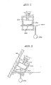
- the make-up water valve unit 44 is positioned such that the float 50 which raises the needle 52 against the seat 54, will drop the needle 52 away from the seat 54 when the water level is lower than the low water mark 40. When this occurs, make-up water will enter the container 10 automatically to ensure the proper operation of the filter unit. Should the filter unit be tilted, a pendulum 56 and cam 58 arrangement is provided to ensure that make-up water does not flood the container. This will only occur if the container 10 is tilted to the right as is shown in Figure 3, when the pendulum 56 will rotate the axle 60 to butt the lobe of the cam 58 against the bottom of the float 50. This will result in the needle 52 obturating the inlet formed within the seat 54.
Landscapes
- Engineering & Computer Science (AREA)
- Chemical & Material Sciences (AREA)
- Chemical Kinetics & Catalysis (AREA)
- Combustion & Propulsion (AREA)
- Mechanical Engineering (AREA)
- General Engineering & Computer Science (AREA)
- Filtering Of Dispersed Particles In Gases (AREA)
- Filtration Of Liquid (AREA)
- Float Valves (AREA)
- Degasification And Air Bubble Elimination (AREA)
- Separation Of Particles Using Liquids (AREA)
Abstract
Description
- This invention relates to a gas filtration unit and more particularly to an intake air filtration unit for internal combustion engines.
- The filtration medium used by the filter is a liquid, which may be water where the filter is applied as an intake air filtration unit for internal combustion engines. In such an application the filter serves the secondary purpose of densifying the gas by the entrainment of the liquid in vapour form.
- According to the invention a gas filtration unit comprises a liquid container, at least one intake gas inlet tube, extending from a source of inlet gas downwardly into the container and opening at a high liquid level within the container, at least one filtered gas outlet formed above the high liquid level in the container and means adapted automatically to vary the liquid level between the high liquid level and a low liquid level, which is below the inlet tube opening, in dependence on the gas flow through the container.
- A plurality of intake gas inlet tubes may be provided which extend substantially vertically downwardly from an intake plenum which is in communication with a source of intake gas through one or more intake gas inlets. The intake gas inlet tube or tubes may extend downwardly into the liquid, but in the preferred form of the invention the tubes open above and preferably just above, the high liquid level.
- The liquid level variation means may be constituted by electronic, electromechanical or a mechanical level variation device,, but in the preferred form of the invention, the filtered gas outlet includes an outlet tube extending downwardly into the container to an opening above the high liquid level and a liquid displacer element is provided and connected to a choke vane located within the outlet tube in such a manner that gas flow past the choke vane will tend to raise the vane within the outlet tube thereby raising the displacer element from the liquid to displace progressively less and less liquid.
- The gas filtration unit may be configured to serve as an intake air filter for an internal combustion engine.
- Some embodiments of the invention will now be described by way of example and with reference to the accompanying drawings in which:
- Figure 1 is a sectional side elevation of the gas filtration unit of the invention illusrating two embodiments, one on either side of a central line;
- Figure 2 is a sectional side elevation on a line 2-2 in Figure 1; and
- Figure 3 is a diagrammatic representation of a water supply valve unit forming part of the filtration unit.
- The filtration unit illustrated is configured to serve as an intake air filtration unit for internal combustion engines and comprises a liquid container 10 with a
removable base 12 secured thereto by means of abolt 14 and wing nut 16. The latter arrangement also secures a cap 18 to the container 10, the cap 18 being formed with a filteredgas outlet 20. - The container 10 is adapted to be charged with
water 22 up to a predetermined high level, which is indicated by anarrow 24. - The intake portion of the filtration unit comprises an intake plenum 26 which is open to atmosphere through intake openings 28. The unit may be configured either as a completely free flow filter by the provision of a cap 18.1 in which a skirt 18.2 provides the only cover for the inlet openings 28, or as a partially obstructed unit using a cap 18.3 which allows the use of a
porous filter material 30, such as a plastics sponge material to be used as a primary cover for the intake openings 28. A plurality ofair intake tubes 32 extend from the plenum downwardly towards theliquid 22 to open just slightly above the highliquid level 24. - The filtered air outlet arrangement includes an outlet tube, constituted by a choke throat 34 extending downwardly into the container 10. A choke vane 36 is located within this throat 34 and is conected ,to a
liquid displacer 38 by means of a connectingsleeve 40. Increased air flow through the choke throat 34 and past the choke vane 36 will result in the choke vane 36 rising within the throat 34 whereby thedisplacer element 38 will be raised from thewater 22 and, as a result, less and less water will be displaced by theelement 38. In consequence, the water level will drop to a low liquid level indicated by anarrow 40 , which is well below theopenings 42 of theinlet tubes 32. - The
displacer 38 is weighted such that the displacer, sleeve and choke vane combination floats at the desired height within thewater 22. - Make-up water may be fed automatically or semi-automatically to the unit by means of a water supply tube feeding a water
supply valve unit 44. Accumulated filtrate may be removed from thebase 12 from time to time by removal and manual flushing of thebase 12. - In operation, intake air will enter the inlet openings 28 in the direction of the
arrows 46 to be drawn through the plenum 26 and thetubes 32 into the free space above thewater level 24. In the process, the air is filtered, partly as a result of the filtration effect of the water temporarily entraining some air but mostly as a result of the downward acceleration of the air in thetubes 32 and the consequential acceleration of any particles within the air to be filtered. This acceleration projects the entrained particles downwardly into the water so that the air which rises upwardly leaves the unit substantially free from impurities. The filtration capabilities of the filter are not affected by the fact that the water level, in certain states of operation of the unit, lies well below theopenings 42 of thetubes 32, since the air velocity, and therefore the downward acceleration of the air entrained particles, is so much greater in these states of operation. - The air is drawn from free space above the
water 22, through thechoke throat 44 and out of theoutlet 20 in the direction of the arrow 48. In the process, the choke vane 36 is drawn upwardly by the passage of the air through the throat 34 and as a result, thedisplacer 38 is raised on thesleeve 40 to lower the water level. This mechanism is entirely self regulatory and will compensate even for sudden large surges of air flowing through the unit. This self regulatory mechanism also has the beneficial effect that when air flow, and therefore air speed through the unit, increases, the surface turbulence of thewater 22 will increase to the extent that the water droplets could be entrained within the air stream issuing from theoutlet 20. By progressively lowering the water level to a point where the water level is well below theopenings 42, the entrainment of water droplets is substantially prevented. - The make-up
water valve unit 44 is positioned such that thefloat 50 which raises theneedle 52 against theseat 54, will drop theneedle 52 away from theseat 54 when the water level is lower than thelow water mark 40. When this occurs, make-up water will enter the container 10 automatically to ensure the proper operation of the filter unit. Should the filter unit be tilted, apendulum 56 andcam 58 arrangement is provided to ensure that make-up water does not flood the container. This will only occur if the container 10 is tilted to the right as is shown in Figure 3, when thependulum 56 will rotate theaxle 60 to butt the lobe of thecam 58 against the bottom of thefloat 50. This will result in theneedle 52 obturating the inlet formed within theseat 54.
Claims (7)
Priority Applications (1)
| Application Number | Priority Date | Filing Date | Title |
|---|---|---|---|
| AT87301537T ATE59567T1 (en) | 1986-02-24 | 1987-02-23 | GAS FILTRATION UNIT. |
Applications Claiming Priority (2)
| Application Number | Priority Date | Filing Date | Title |
|---|---|---|---|
| ZA861365 | 1986-02-24 | ||
| ZA861365 | 1986-02-24 |
Publications (3)
| Publication Number | Publication Date |
|---|---|
| EP0240132A2 true EP0240132A2 (en) | 1987-10-07 |
| EP0240132A3 EP0240132A3 (en) | 1988-07-06 |
| EP0240132B1 EP0240132B1 (en) | 1991-01-02 |
Family
ID=60320553
Family Applications (1)
| Application Number | Title | Priority Date | Filing Date |
|---|---|---|---|
| EP87301537A Expired - Lifetime EP0240132B1 (en) | 1986-02-24 | 1987-02-23 | Gas filtration unit |
Country Status (12)
| Country | Link |
|---|---|
| US (1) | US4746336A (en) |
| EP (1) | EP0240132B1 (en) |
| JP (1) | JPS62254820A (en) |
| AR (1) | AR241038A1 (en) |
| AT (1) | ATE59567T1 (en) |
| AU (1) | AU597334B2 (en) |
| BR (1) | BR8700842A (en) |
| DE (1) | DE3766864D1 (en) |
| ES (1) | ES2020560B3 (en) |
| GR (1) | GR3001686T3 (en) |
| IN (1) | IN168371B (en) |
| ZA (1) | ZA87947B (en) |
Families Citing this family (8)
| Publication number | Priority date | Publication date | Assignee | Title |
|---|---|---|---|---|
| US5871562A (en) * | 1997-07-16 | 1999-02-16 | Culoso; Richard | Air conditioning odor control apparatus and method |
| US6905537B1 (en) * | 2003-07-09 | 2005-06-14 | Garry Parkinson Isaacs | Machine and process for filterless removal of particles and organisms from ambient air, carpets and furnishings |
| RU2257943C1 (en) * | 2004-09-20 | 2005-08-10 | Открытое акционерное общество "Энергомашкорпорация" | Device for wet purification of air |
| CN102996295A (en) * | 2012-12-12 | 2013-03-27 | 江西省亿达置业有限公司 | Water core air purifier for automobile |
| US12134071B2 (en) | 2017-12-22 | 2024-11-05 | Awe Solutions Inc. | Air purifying machine and process |
| US12134072B2 (en) | 2017-12-22 | 2024-11-05 | Clean Air Zone Inc. | Air purifying machine and process |
| US10969125B2 (en) | 2017-12-22 | 2021-04-06 | Clean Air Zone Inc. | Air purification system |
| US11946792B2 (en) | 2021-06-28 | 2024-04-02 | Clean Air Zone Inc. | Level sensor |
Family Cites Families (16)
| Publication number | Priority date | Publication date | Assignee | Title |
|---|---|---|---|---|
| BE510200A (en) * | ||||
| US919249A (en) * | 1908-10-16 | 1909-04-20 | John Ruddiman | Gas-cleanser. |
| US1200202A (en) * | 1915-11-02 | 1916-10-03 | John M Kroyer | Dust-excluding means for explosive-motors. |
| US1214372A (en) * | 1916-06-06 | 1917-01-30 | Floyd T Romberger | Apparatus for supplying water-vapor to the cylinders of an internal-combustion engine. |
| DE384907C (en) * | 1918-07-17 | 1923-11-09 | Henry Ford | air cleaner |
| US1664333A (en) * | 1926-10-26 | 1928-03-27 | Doc G Taylor | Air cleaner |
| US1817265A (en) * | 1930-02-07 | 1931-08-04 | Adolfo F Pando | Air filter for internal combustion engines |
| US1946291A (en) * | 1931-09-24 | 1934-02-06 | Arthur W Miller | Air cleaner |
| US1960260A (en) * | 1933-01-06 | 1934-05-29 | Russel D Acton | Air cleaner |
| US2403545A (en) * | 1943-06-05 | 1946-07-09 | American Air Filter Co | Dust arrester liquid level control |
| FR1278710A (en) * | 1960-11-03 | 1961-12-15 | Accessories Company Ltd | Air filter improvements |
| BE627057A (en) * | 1964-01-10 | |||
| US3517485A (en) * | 1968-01-04 | 1970-06-30 | Modern Equipment Co | Apparatus for treating gases |
| US3766717A (en) * | 1972-06-12 | 1973-10-23 | Josam Dev Inc | Particle collector for cleaning gases |
| US3980080A (en) * | 1974-12-23 | 1976-09-14 | Rudolph Muto | Air filtration gas mass |
| IT1091078B (en) * | 1977-10-25 | 1985-06-26 | Whitehead Moto Fides Stabil | OIL BATH AIR FILTER |
-
1987
- 1987-02-10 ZA ZA87947A patent/ZA87947B/xx unknown
- 1987-02-17 IN IN137/DEL/87A patent/IN168371B/en unknown
- 1987-02-19 AU AU69063/87A patent/AU597334B2/en not_active Ceased
- 1987-02-23 BR BR8700842A patent/BR8700842A/en not_active IP Right Cessation
- 1987-02-23 AT AT87301537T patent/ATE59567T1/en not_active IP Right Cessation
- 1987-02-23 DE DE8787301537T patent/DE3766864D1/en not_active Expired - Lifetime
- 1987-02-23 ES ES87301537T patent/ES2020560B3/en not_active Expired - Lifetime
- 1987-02-23 US US07/017,699 patent/US4746336A/en not_active Expired - Lifetime
- 1987-02-23 EP EP87301537A patent/EP0240132B1/en not_active Expired - Lifetime
- 1987-02-24 AR AR306836A patent/AR241038A1/en active
- 1987-02-24 JP JP62041257A patent/JPS62254820A/en active Pending
-
1991
- 1991-03-29 GR GR91400409T patent/GR3001686T3/en unknown
Also Published As
| Publication number | Publication date |
|---|---|
| ZA87947B (en) | 1987-08-03 |
| AU6906387A (en) | 1987-08-27 |
| DE3766864D1 (en) | 1991-02-07 |
| AR241038A1 (en) | 1991-04-30 |
| AU597334B2 (en) | 1990-05-31 |
| EP0240132A3 (en) | 1988-07-06 |
| EP0240132B1 (en) | 1991-01-02 |
| GR3001686T3 (en) | 1992-11-23 |
| JPS62254820A (en) | 1987-11-06 |
| ATE59567T1 (en) | 1991-01-15 |
| IN168371B (en) | 1991-03-23 |
| BR8700842A (en) | 1987-12-15 |
| ES2020560B3 (en) | 1991-08-16 |
| US4746336A (en) | 1988-05-24 |
| AR241038A2 (en) | 1991-04-30 |
Similar Documents
| Publication | Publication Date | Title |
|---|---|---|
| US4746336A (en) | Gas filtration unit | |
| US3834365A (en) | Crankcase scavenger and smog reducer | |
| GB2129329A (en) | Fuel treatment device | |
| US3701513A (en) | Fuel feeding apparatus | |
| JP2003508678A (en) | Air filter for filtering intake air for automotive internal combustion engines | |
| US4306520A (en) | Water vapor injector for combustion engine air intake | |
| US3892547A (en) | Vaporizing carburetor | |
| US3653643A (en) | Carburetor | |
| EP0292446B1 (en) | Fuel feed device, particularly for internal combustion engines, comprising fuel filtering and emulsifying members | |
| US3685504A (en) | Fuel tank ventilation in motor vehicles | |
| EP0083653A1 (en) | DEVICE FOR PRODUCING A MIXTURE OF FLAMMABLE LIQUID AND AIR. | |
| AU570618B2 (en) | Adding a liquid to an engine intake airflow | |
| US1471705A (en) | Apparatus for treating fresh petroleum | |
| US972282A (en) | Liquid-fuel purifier and gaged governor. | |
| US1746619A (en) | Float-operated valve | |
| CN212508578U (en) | Electric control carburetor of gasoline engine | |
| US1058407A (en) | Carbureter. | |
| JPS6138645Y2 (en) | ||
| US2080570A (en) | Carburetor | |
| SU1613663A1 (en) | Device for withdrawing air from pressure oil line | |
| US860848A (en) | Carbureter. | |
| US821081A (en) | Carbureter. | |
| JPS622293Y2 (en) | ||
| CN2330806Y (en) | A hydraulic acceleration device | |
| US1357140A (en) | Air-filter for gas-engines |
Legal Events
| Date | Code | Title | Description |
|---|---|---|---|
| PUAI | Public reference made under article 153(3) epc to a published international application that has entered the european phase |
Free format text: ORIGINAL CODE: 0009012 |
|
| AK | Designated contracting states |
Kind code of ref document: A2 Designated state(s): AT BE CH DE ES FR GB GR IT LI LU NL SE |
|
| PUAL | Search report despatched |
Free format text: ORIGINAL CODE: 0009013 |
|
| AK | Designated contracting states |
Kind code of ref document: A3 Designated state(s): AT BE CH DE ES FR GB GR IT LI LU NL SE |
|
| 17P | Request for examination filed |
Effective date: 19881222 |
|
| 17Q | First examination report despatched |
Effective date: 19890414 |
|
| GRAA | (expected) grant |
Free format text: ORIGINAL CODE: 0009210 |
|
| AK | Designated contracting states |
Kind code of ref document: B1 Designated state(s): AT BE CH DE ES FR GB GR IT LI LU NL SE |
|
| REF | Corresponds to: |
Ref document number: 59567 Country of ref document: AT Date of ref document: 19910115 Kind code of ref document: T |
|
| REF | Corresponds to: |
Ref document number: 3766864 Country of ref document: DE Date of ref document: 19910207 |
|
| ITF | It: translation for a ep patent filed | ||
| ET | Fr: translation filed | ||
| PLBE | No opposition filed within time limit |
Free format text: ORIGINAL CODE: 0009261 |
|
| STAA | Information on the status of an ep patent application or granted ep patent |
Free format text: STATUS: NO OPPOSITION FILED WITHIN TIME LIMIT |
|
| 26N | No opposition filed | ||
| REG | Reference to a national code |
Ref country code: GR Ref legal event code: FG4A Free format text: 3001686 |
|
| GBPC | Gb: european patent ceased through non-payment of renewal fee | ||
| REG | Reference to a national code |
Ref country code: GB Ref legal event code: 728C |
|
| REG | Reference to a national code |
Ref country code: GB Ref legal event code: 728C |
|
| EPTA | Lu: last paid annual fee | ||
| EAL | Se: european patent in force in sweden |
Ref document number: 87301537.4 |
|
| REG | Reference to a national code |
Ref country code: GB Ref legal event code: IF02 |
|
| PGFP | Annual fee paid to national office [announced via postgrant information from national office to epo] |
Ref country code: SE Payment date: 20020808 Year of fee payment: 16 Ref country code: GB Payment date: 20020808 Year of fee payment: 16 Ref country code: BE Payment date: 20020808 Year of fee payment: 16 |
|
| PGFP | Annual fee paid to national office [announced via postgrant information from national office to epo] |
Ref country code: CH Payment date: 20020809 Year of fee payment: 16 Ref country code: AT Payment date: 20020809 Year of fee payment: 16 |
|
| PGFP | Annual fee paid to national office [announced via postgrant information from national office to epo] |
Ref country code: LU Payment date: 20020812 Year of fee payment: 16 |
|
| PGFP | Annual fee paid to national office [announced via postgrant information from national office to epo] |
Ref country code: DE Payment date: 20020827 Year of fee payment: 16 |
|
| PGFP | Annual fee paid to national office [announced via postgrant information from national office to epo] |
Ref country code: GR Payment date: 20020828 Year of fee payment: 16 Ref country code: FR Payment date: 20020828 Year of fee payment: 16 |
|
| PGFP | Annual fee paid to national office [announced via postgrant information from national office to epo] |
Ref country code: ES Payment date: 20020829 Year of fee payment: 16 |
|
| PGFP | Annual fee paid to national office [announced via postgrant information from national office to epo] |
Ref country code: NL Payment date: 20020830 Year of fee payment: 16 |
|
| PG25 | Lapsed in a contracting state [announced via postgrant information from national office to epo] |
Ref country code: LU Free format text: LAPSE BECAUSE OF NON-PAYMENT OF DUE FEES Effective date: 20030223 Ref country code: GB Free format text: LAPSE BECAUSE OF NON-PAYMENT OF DUE FEES Effective date: 20030223 Ref country code: AT Free format text: LAPSE BECAUSE OF NON-PAYMENT OF DUE FEES Effective date: 20030223 |
|
| PG25 | Lapsed in a contracting state [announced via postgrant information from national office to epo] |
Ref country code: SE Free format text: LAPSE BECAUSE OF NON-PAYMENT OF DUE FEES Effective date: 20030224 Ref country code: ES Free format text: LAPSE BECAUSE OF NON-PAYMENT OF DUE FEES Effective date: 20030224 |
|
| PG25 | Lapsed in a contracting state [announced via postgrant information from national office to epo] |
Ref country code: LI Free format text: LAPSE BECAUSE OF NON-PAYMENT OF DUE FEES Effective date: 20030228 Ref country code: CH Free format text: LAPSE BECAUSE OF NON-PAYMENT OF DUE FEES Effective date: 20030228 Ref country code: BE Free format text: LAPSE BECAUSE OF NON-PAYMENT OF DUE FEES Effective date: 20030228 |
|
| PG25 | Lapsed in a contracting state [announced via postgrant information from national office to epo] |
Ref country code: NL Free format text: LAPSE BECAUSE OF NON-PAYMENT OF DUE FEES Effective date: 20030901 |
|
| PG25 | Lapsed in a contracting state [announced via postgrant information from national office to epo] |
Ref country code: DE Free format text: LAPSE BECAUSE OF NON-PAYMENT OF DUE FEES Effective date: 20030902 |
|
| PG25 | Lapsed in a contracting state [announced via postgrant information from national office to epo] |
Ref country code: GR Free format text: LAPSE BECAUSE OF NON-PAYMENT OF DUE FEES Effective date: 20030904 |
|
| EUG | Se: european patent has lapsed | ||
| GBPC | Gb: european patent ceased through non-payment of renewal fee | ||
| REG | Reference to a national code |
Ref country code: CH Ref legal event code: PL |
|
| PG25 | Lapsed in a contracting state [announced via postgrant information from national office to epo] |
Ref country code: FR Free format text: LAPSE BECAUSE OF NON-PAYMENT OF DUE FEES Effective date: 20031031 |
|
| NLV4 | Nl: lapsed or anulled due to non-payment of the annual fee |
Effective date: 20030901 |
|
| REG | Reference to a national code |
Ref country code: FR Ref legal event code: ST |
|
| REG | Reference to a national code |
Ref country code: ES Ref legal event code: FD2A Effective date: 20030224 |
|
| PG25 | Lapsed in a contracting state [announced via postgrant information from national office to epo] |
Ref country code: IT Free format text: LAPSE BECAUSE OF NON-PAYMENT OF DUE FEES;WARNING: LAPSES OF ITALIAN PATENTS WITH EFFECTIVE DATE BEFORE 2007 MAY HAVE OCCURRED AT ANY TIME BEFORE 2007. THE CORRECT EFFECTIVE DATE MAY BE DIFFERENT FROM THE ONE RECORDED. Effective date: 20050223 |