EP0240066A2 - Lampe à décharge à haute intensité comportant plusieurs dispositifs à décharge à amorçage préférentiel - Google Patents
Lampe à décharge à haute intensité comportant plusieurs dispositifs à décharge à amorçage préférentiel Download PDFInfo
- Publication number
- EP0240066A2 EP0240066A2 EP87200520A EP87200520A EP0240066A2 EP 0240066 A2 EP0240066 A2 EP 0240066A2 EP 87200520 A EP87200520 A EP 87200520A EP 87200520 A EP87200520 A EP 87200520A EP 0240066 A2 EP0240066 A2 EP 0240066A2
- Authority
- EP
- European Patent Office
- Prior art keywords
- discharge
- starting
- discharge devices
- devices
- voltage
- Prior art date
- Legal status (The legal status is an assumption and is not a legal conclusion. Google has not performed a legal analysis and makes no representation as to the accuracy of the status listed.)
- Granted
Links
Images

Classifications
-
- H—ELECTRICITY
- H01—ELECTRIC ELEMENTS
- H01J—ELECTRIC DISCHARGE TUBES OR DISCHARGE LAMPS
- H01J61/00—Gas-discharge or vapour-discharge lamps
- H01J61/02—Details
- H01J61/30—Vessels; Containers
- H01J61/34—Double-wall vessels or containers
-
- H—ELECTRICITY
- H01—ELECTRIC ELEMENTS
- H01J—ELECTRIC DISCHARGE TUBES OR DISCHARGE LAMPS
- H01J61/00—Gas-discharge or vapour-discharge lamps
- H01J61/02—Details
- H01J61/54—Igniting arrangements, e.g. promoting ionisation for starting
-
- H—ELECTRICITY
- H01—ELECTRIC ELEMENTS
- H01J—ELECTRIC DISCHARGE TUBES OR DISCHARGE LAMPS
- H01J61/00—Gas-discharge or vapour-discharge lamps
- H01J61/02—Details
- H01J61/54—Igniting arrangements, e.g. promoting ionisation for starting
- H01J61/541—Igniting arrangements, e.g. promoting ionisation for starting using a bimetal switch
- H01J61/544—Igniting arrangements, e.g. promoting ionisation for starting using a bimetal switch and an auxiliary electrode outside the vessel
-
- H—ELECTRICITY
- H01—ELECTRIC ELEMENTS
- H01J—ELECTRIC DISCHARGE TUBES OR DISCHARGE LAMPS
- H01J61/00—Gas-discharge or vapour-discharge lamps
- H01J61/92—Lamps with more than one main discharge path
Definitions
- the present invention relates to high intensity discharge lamps, and more particularly high intensity discharge lamps having multiple discharge devices.
- High intensity discharge (HID) lamps generally include a discharge device having a translucent or transparent vessel that contains an ionizable material. Additionally, the discharge device may include a pair of discharge electrodes within the discharge vessel. In operation, an electrical discharge is developed within the ionizable material amd emits light.
- high pressure sodium discharge lamps have a mercury-sodium amalgam within the discharge vessel, and an inert starting gas. The starting gas is ionized to vaporize some of the amalgam, the vaporized mercury and sodium are ionized, and an intense light-emitting electrical discharge is formed.
- the difficulty in restarting an HID lamp after the discharge has been interrupted is well-known.
- the gas pressure within the discharge vessel attains several atmospheres.
- the high internal pressure makes it difficult to reinitiate the discharge, i.e. restart the lamp. Consequently, the discharge vessel must cool until its internal pressure has dropped sufficiently to allow the discharge to be reestablished.
- the time required for the discharge tube to cool sufficiently to reestablish the discharge is called the hot restart delay.
- a momentary power interruption can result in an interruption in lighting service that lasts much longer than the power interruption.
- auxiliary incandescent lamps have been addressed in different ways.
- One approach is to provide auxiliary incandescent lamps; however, such auxiliary lamps also require control circuitry for operation during periods of hot restart delay.
- This auxiliary equipment creates additional expense and creates a more elaborate system that that required for just operating the HID lamps.
- U.S. Patent No. 4,287,454 to Feuersanger et al discloses a high pressure discharge lamp in which a pair of lamp discharge devices are contained within the same lamp and connected in parallel. When a starting voltage is applied to the lamp one of the discharge devices operates first, and effectively shunts the second discharge device with a low impedance thereby preventing it from operating. Only the operative discharge device heats sufficiently to elevate its internal pressure and increase its starting voltage. Consequently, if the operating voltage applied to the lamp is interrupted, a reapplied voltage will start the previously inoperative discharge device which will operate without experiencing a hot restart delay.
- Optical shading caused by one discharge tube blocking the light from another does not occur in the prior art lamp having a single discharge tube and an auxiliary discharge gap within the lamp envelope.
- optical shading is avoided by positioning the discharge tubes aligned axially.
- This arrangement of discharge tubes is not practicable for high wattage lamps.
- a 400 watt high pressure sodium HID lamp typically has a discharge vessel about 4.5 inches long and a lamp outer envelope almost eight inches long. In such a lamp having multiple discharge tubes it would not be practicable to axially align the discharge tubes.
- Optical shading of one discharge device by another is unavoidable when multiple discharge devices are arranged side by side.
- luminaire design if HID lamps having multiple discharge devices could be made so that the same discharge device always started first, when the lamp is started from a cool condition.
- the luminaire could be designed to minimize the effect of optical shading by the inoperative discharge device and maximize the use of the light emitted by the preferentially starting discharge device.
- An object of the invention is to provide a high intensity discharge lamp having multiple high pressure discharges devices, in which one of the discharge device starts preferentially.
- a high intensity discharge lamp comprises a plurality of high intensity discharge devices.
- Each of the discharge devices is responsive to an applied voltage developing an electrical discharge that emits high intensity light.
- the discharge devices heat during operation and exhibit a substantially increased starting voltage when heated.
- the lamp further comprises mounting means for mounting the discharge devices relative to each other such that heating of one discharge device during operation does not cause substantial heating of another discharge device that is inoperative.
- the lamp further comprises means for preferentially starting one of the discharge devices when the discharge devices are unheated and exhibit their normal starting voltage with another of the discharge devices remaining inoperative.
- the discharge devices are comprised of a discharge vessel, a pair of discharge electrodes within the discharge vessel, and a discharge vessel filling of an inert starting gas and an ionizable material.
- the means for preferentially starting is defined by the inert starting gas within one of the discharge devices having a pressure less than the inert starting gas pressure of the other discharge devices.
- the means for preferentially starting is comprised of a metallic starting aid positioned proximate one of the discharge devices for imparting to the discharge device a lower starting voltage than that of the other discharge device.
- the starting aid may advantageously be a metal wire wrapped around the discharge envelope.
- the lamp according to the invention is comprised of an outer glass envelope 1 having a screw base 2 at one end thereof.
- a pair of discharge devices 3 and 4 are housed within the transparent envelope 1 and are energizable for emitting light.
- the discharge devices 3 and 4 are high pressure discharge lamp discharge tube assemblies.
- Each of the discharge tube assemblies are comprised of a discharge tube, a pair of internal discharge electrodes within the discharge tube and a fill comprised of an inert starting gas and an ionizable material.
- Connection to the internal discharge electrodes of the discharge device 3 is made by conductive lead-throughs 5 and 6, and to the internal discharge electrodes of the discharge device 4 by conductive lead-throughs 7 and 8.
- the discharge devices 3 and 4 are electrically connected in parallel by the metallic support structure which supports the discharge devices within the lamp envelope 1.
- Upstanding support rod 9 extends upwardly and supports horizontal member 10 and in anchored at its upper end 11.
- the horizontal member 10 has downwardly extending end portions which extend to respective tubular lead-throughs 5 and 7 for supporting the upper ends of the discharge devices 3 and 4.
- Electrical connection between the lead-throughs 5 and 7 and the horizontal member 10 is provided by metallic ribbons 12 and 13, each of which is connected between a respective electrode lead-throughs 5 and 7 and the horizontal member 10.
- the support rod 9 extends downwardly to the press 14 and makes connection with a wire lead-through 15.
- the lead-through 15 in turn extends through the press 14 and connects to the screw base 2 to complete the electrical circuit from the screw base 2 to the upper electrodes of the discharge assemblies 3 and 4.
- the lower electrode lead-throughs 6 and 8 are connected together mechanically and electrically by the metallic strap 16. This strap is solidly attached to the vertical wire 17 which extends through the press 14 and makes connection with the screw base 2.
- discharge devices 3 and 4 are spaced sufficiently far apart so that operation of discharge device 3 does not heat discharge device 4 too much and raise its starting voltage above that supplied by the lamp starter circuit. Thus, it will be possible to start the discharge device 4 even if discharge device 3 is heated to the point of exhibiting hot restart delay.
- the electrical circuit defined by the metallic support structure is illustrated schematically in Fig. 5 in which the conductive paths are identified with the same reference numerals that are used in Figs. 1-4 to identify the mechanical elements defining those conductive paths.
- the discharge devices 3 and 4 are connected electrically in parallel by element 10 and straps 12 and 13, and by strap 16. Consequently, when a potential difference is applied across the screw base 2 the same potential difference is applied across the discharge device 3 and the discharge device 4. If the two discharge devices have substantially the same starting voltage, which discharge device starts first is unpredictable.
- a starting aid shown schematically in Fig. 5, coacts with the discharge device 3 to start it first, even when the same potential differences are applied across both discharge devices.
- the starting aid shown schematically in Fig. 5 can be realized by manufacturing the discharge device 3 with a lower inert fill gas pressure than that of the discharge device 4 to impart a lower starting voltages to it.
- the respective starting voltages must be sufficiently different so that the discharge device 3 will preferentially start even after the respective starting voltages undergo the inevitable voltage rise that occurs over the life of some HID lamps.
- the starting voltage of both discharge devices 3 and 4 must be within the range of conventional starting voltages.
- the actual starting voltage must be sufficiently close to its design value so that for large numbers of discharge devices those intended to have the lower starting voltage will always have a starting voltage that is lower by a certain value than those intended to have the higher starting voltage.
- 400 watt high pressure sodium HID lamps were fabricated having discharge devices with different fill gas pressures. These lamps had discharge devices containing a typical sodium-mercury amalgam fill comprised of 18.4 weight % of sodium and 81.6 weight % of mercury.
- the inert fill gas was pure xenon.
- the discharge devices were identical except that nineteen of them had a xenon fill pressure of 16 Torr for a nominal starting voltage of 2100 volts, and forty-five of them had a xenon fill pressure of 20 Torr for a nominal starting voltage of 2600 volts.
- the data shows that the starting voltages of the individual discharge devices within each group fell within a range of 350 volts, and the difference between the maximum starting voltage among the discharge devices having the lower nominal starting voltage and the minimum starting voltage among the discharge devices having the higher nominal starting voltage was 200 volts.
- the data shows that if randomly selected discharge devices were selected from the two groups and included in the same lamp, in the worst case the starting voltage of one discharge device would be 200 volts lower than the higher starting voltage.
- the starting voltage of a high pressure sodium discharge device can be expected to rise by about 100 volts over its life, which is just one half the worst case starting voltage difference between the two discharge devices.
- the discharge device with the lower starting voltage will preferentially start over the entire life of the lamp, and the use of different inert gas fill pressures to create preferential starting is practical for commercial lamps.
- Lamps were made having two discharge devices, with different starting voltages, from the discharge devices just described. In each case the discharge device having the lower starting voltage started first. During lamp operation, when power was interrupted resulting in interruption of the operating and heated discharge device, the second discharge device having the higher starting voltage would, upom reapplication of lamp power, start without hot restart delay.
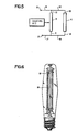
- structure defining the preferential starting aid is defined by a metallic helical coil 18 wound around one of the discharge devices.
- the operation of this type of starting aid is described in detail in U.S. Patent 4,491,766 which is incorporated herein by reference.
- the metal spiral 18 is electrically connected to the support rod 9 through the diode 19.
- the diode has a polarity effective to impart a positive potential to the metal spiral 18 during each alternating half cycle of the applied voltage. For at least a half of each alternating current cycle the potential which is applied to the metal spiral 18 will be positive and opposite that of one of the discharge electrodes. This positive voltage causes local ionization within the discharge device and an incipient discharge. Electrons from the discharge are accelerated by the field between the discharge electrodes and enhance the formation of the main discharge. The main discharge occurs at a lower voltage than if the metal spiral 18 were not present and biased.
- discharge devices of the electrodeless type can be used.
Landscapes
- Discharge Lamps And Accessories Thereof (AREA)
- Circuit Arrangements For Discharge Lamps (AREA)
Applications Claiming Priority (2)
| Application Number | Priority Date | Filing Date | Title |
|---|---|---|---|
| US06/846,424 US4788475A (en) | 1986-03-31 | 1986-03-31 | Multiple discharge device hid lamp with preferential starting |
| US846424 | 1986-03-31 |
Publications (3)
| Publication Number | Publication Date |
|---|---|
| EP0240066A2 true EP0240066A2 (fr) | 1987-10-07 |
| EP0240066A3 EP0240066A3 (en) | 1989-11-15 |
| EP0240066B1 EP0240066B1 (fr) | 1993-10-27 |
Family
ID=25297889
Family Applications (1)
| Application Number | Title | Priority Date | Filing Date |
|---|---|---|---|
| EP87200520A Expired - Lifetime EP0240066B1 (fr) | 1986-03-31 | 1987-03-23 | Lampe à décharge à haute intensité comportant plusieurs dispositifs à décharge à amorçage préférentiel |
Country Status (4)
| Country | Link |
|---|---|
| US (1) | US4788475A (fr) |
| EP (1) | EP0240066B1 (fr) |
| CA (1) | CA1280460C (fr) |
| DE (1) | DE3787910T2 (fr) |
Cited By (3)
| Publication number | Priority date | Publication date | Assignee | Title |
|---|---|---|---|---|
| EP0477914A2 (fr) * | 1990-09-25 | 1992-04-01 | Toshiba Lighting & Technology Corporation | Lampe à décharge à haute pression et son procédé d'allumage |
| US8029151B2 (en) | 2008-03-27 | 2011-10-04 | Abl Ip Holding Llc | Back-up lighting system |
| US8845152B2 (en) | 2011-09-28 | 2014-09-30 | Abl Ip Holding Llc | Pole mounted enclosures for luminaires |
Families Citing this family (10)
| Publication number | Priority date | Publication date | Assignee | Title |
|---|---|---|---|---|
| US5408157A (en) * | 1993-03-09 | 1995-04-18 | North American Philips Corporation | Dual arc tube discharge lamp having a lamp frame with coplanar spot welds and slip-free construction |
| US5661367A (en) * | 1996-08-08 | 1997-08-26 | Philips Electronics North America Corporation | High pressure series arc discharge lamp construction with simplified starting aid |
| US5909082A (en) * | 1997-05-06 | 1999-06-01 | General Electric Company | Starting aid for high intensity discharge lamps |
| US5898273A (en) * | 1997-07-01 | 1999-04-27 | General Electric Company | Metal halide lamp with pre-start arc tube heater |
| US6456005B1 (en) | 2000-10-31 | 2002-09-24 | General Electric Company | Materials and methods for application of conducting members on arc tubes |
| US6538377B1 (en) | 2000-11-03 | 2003-03-25 | General Electric Company | Means for applying conducting members to arc tubes |
| US6563265B1 (en) | 2000-11-06 | 2003-05-13 | General Electric Company | Applying prealloyed powders as conducting members to arc tubes |
| US20100134027A1 (en) * | 2008-12-03 | 2010-06-03 | Koninklijke Philips Electronics N.V. | Multi-lamp hid luminaire with cycling switch |
| CN101541137A (zh) * | 2009-04-24 | 2009-09-23 | 湖州华氏照明有限公司 | 一种hid灯即开即亮的实现方法及相应的hid灯 |
| US9030099B2 (en) * | 2013-05-09 | 2015-05-12 | Osram Sylvania Inc. | High pressure discharge lamp with multiple arc tubes |
Citations (2)
| Publication number | Priority date | Publication date | Assignee | Title |
|---|---|---|---|---|
| DE2951740A1 (de) * | 1978-12-22 | 1980-06-26 | Mitsubishi Electric Corp | Beleuchtungseinrichtung |
| EP0030730A2 (fr) * | 1979-12-17 | 1981-06-24 | GTE Laboratories Incorporated | Lampes à décharge à haute pression à redémarrage rapide |
Family Cites Families (4)
| Publication number | Priority date | Publication date | Assignee | Title |
|---|---|---|---|---|
| DE2222365A1 (de) * | 1972-05-06 | 1973-11-22 | Multiblitz Mannesmann Gmbh Co | Blitzleuchtenanordnung |
| US4185232A (en) * | 1978-08-28 | 1980-01-22 | Gte Sylvania Incorporated | Multiple flashlamp operating circuit |
| NL188821C (nl) * | 1979-11-28 | 1992-10-01 | Mitsubishi Electric Corp | Gasontladingslamp. |
| US4475062A (en) * | 1982-05-06 | 1984-10-02 | Michael Radenkovich | Economy device for fluorescent lighting fixtures |
-
1986
- 1986-03-31 US US06/846,424 patent/US4788475A/en not_active Expired - Fee Related
-
1987
- 1987-03-23 DE DE87200520T patent/DE3787910T2/de not_active Expired - Fee Related
- 1987-03-23 EP EP87200520A patent/EP0240066B1/fr not_active Expired - Lifetime
- 1987-03-26 CA CA000533097A patent/CA1280460C/fr not_active Expired - Lifetime
Patent Citations (2)
| Publication number | Priority date | Publication date | Assignee | Title |
|---|---|---|---|---|
| DE2951740A1 (de) * | 1978-12-22 | 1980-06-26 | Mitsubishi Electric Corp | Beleuchtungseinrichtung |
| EP0030730A2 (fr) * | 1979-12-17 | 1981-06-24 | GTE Laboratories Incorporated | Lampes à décharge à haute pression à redémarrage rapide |
Cited By (5)
| Publication number | Priority date | Publication date | Assignee | Title |
|---|---|---|---|---|
| EP0477914A2 (fr) * | 1990-09-25 | 1992-04-01 | Toshiba Lighting & Technology Corporation | Lampe à décharge à haute pression et son procédé d'allumage |
| EP0477914A3 (en) * | 1990-09-25 | 1992-10-28 | Toshiba Lighting & Technology Corporation | High-pressure discharge lamp and lighting method |
| US5276385A (en) * | 1990-09-25 | 1994-01-04 | Toshiba Lighting & Technology Corporation | High-pressure discharge lamp and lighting method |
| US8029151B2 (en) | 2008-03-27 | 2011-10-04 | Abl Ip Holding Llc | Back-up lighting system |
| US8845152B2 (en) | 2011-09-28 | 2014-09-30 | Abl Ip Holding Llc | Pole mounted enclosures for luminaires |
Also Published As
| Publication number | Publication date |
|---|---|
| EP0240066A3 (en) | 1989-11-15 |
| EP0240066B1 (fr) | 1993-10-27 |
| DE3787910T2 (de) | 1994-05-05 |
| US4788475A (en) | 1988-11-29 |
| DE3787910D1 (de) | 1993-12-02 |
| CA1280460C (fr) | 1991-02-19 |
Similar Documents
| Publication | Publication Date | Title |
|---|---|---|
| US4788475A (en) | Multiple discharge device hid lamp with preferential starting | |
| US5661367A (en) | High pressure series arc discharge lamp construction with simplified starting aid | |
| US4287454A (en) | High pressure discharge lamps with fast restart | |
| US3746914A (en) | Arc discharge tube with surrounding starting coil | |
| US3900753A (en) | High pressure sodium vapor lamp having low starting voltage | |
| US4491766A (en) | High pressure electric discharge lamp employing a metal spiral with positive potential | |
| US2774918A (en) | Electric discharge device | |
| EP0607633B1 (fr) | Lampe à décharge basse pression sans électrode | |
| US4508993A (en) | Fluorescent lamp without ballast | |
| EP0604220A1 (fr) | Montage de lampes fluorescente et à incandescence | |
| EP0060665B1 (fr) | Lampe de décharge à vapeur métallique et à haute pression | |
| US5066892A (en) | Glow discharge lamp with incandescent filament | |
| EP0748578A1 (fr) | Systeme d'eclairage pourvu d'un dispositif de reduction de la consommation en watt | |
| US2899583A (en) | macksoud | |
| US4317069A (en) | Means and method for controlling lumen output and power consumption of phosphor excitable lamps | |
| US5207503A (en) | Xenon festoon style lamp | |
| US4742275A (en) | High pressure metal vapor discharge lamp with starting element | |
| US4910433A (en) | Emitterless SDN electrode | |
| US5142188A (en) | High pressure discharge lamp utilizing an unsaturated type discharge tube | |
| JP4611283B2 (ja) | 蛍光ランプ及び延長手段のアセンブリ | |
| CA2057271A1 (fr) | Lampe a decharge a haute pression | |
| EP0085487A2 (fr) | Lampes à décharge | |
| US2110597A (en) | Discharge lamp | |
| JPH04501485A (ja) | カソード上に2つの過熱点を発生するサーマルスイッチを備えたグロー放電ランプ | |
| CN1316553C (zh) | 高压放电灯 |
Legal Events
| Date | Code | Title | Description |
|---|---|---|---|
| PUAI | Public reference made under article 153(3) epc to a published international application that has entered the european phase |
Free format text: ORIGINAL CODE: 0009012 |
|
| AK | Designated contracting states |
Kind code of ref document: A2 Designated state(s): DE FR GB |
|
| PUAL | Search report despatched |
Free format text: ORIGINAL CODE: 0009013 |
|
| AK | Designated contracting states |
Kind code of ref document: A3 Designated state(s): DE FR GB |
|
| 17P | Request for examination filed |
Effective date: 19900511 |
|
| 17Q | First examination report despatched |
Effective date: 19920706 |
|
| GRAA | (expected) grant |
Free format text: ORIGINAL CODE: 0009210 |
|
| AK | Designated contracting states |
Kind code of ref document: B1 Designated state(s): DE FR GB |
|
| REF | Corresponds to: |
Ref document number: 3787910 Country of ref document: DE Date of ref document: 19931202 |
|
| ET | Fr: translation filed | ||
| REG | Reference to a national code |
Ref country code: FR Ref legal event code: CD |
|
| PLBE | No opposition filed within time limit |
Free format text: ORIGINAL CODE: 0009261 |
|
| STAA | Information on the status of an ep patent application or granted ep patent |
Free format text: STATUS: NO OPPOSITION FILED WITHIN TIME LIMIT |
|
| 26N | No opposition filed | ||
| PGFP | Annual fee paid to national office [announced via postgrant information from national office to epo] |
Ref country code: GB Payment date: 19950228 Year of fee payment: 9 |
|
| PGFP | Annual fee paid to national office [announced via postgrant information from national office to epo] |
Ref country code: FR Payment date: 19950329 Year of fee payment: 9 |
|
| PGFP | Annual fee paid to national office [announced via postgrant information from national office to epo] |
Ref country code: DE Payment date: 19950529 Year of fee payment: 9 |
|
| PG25 | Lapsed in a contracting state [announced via postgrant information from national office to epo] |
Ref country code: GB Effective date: 19960323 |
|
| GBPC | Gb: european patent ceased through non-payment of renewal fee |
Effective date: 19960323 |
|
| PG25 | Lapsed in a contracting state [announced via postgrant information from national office to epo] |
Ref country code: FR Effective date: 19961129 |
|
| PG25 | Lapsed in a contracting state [announced via postgrant information from national office to epo] |
Ref country code: DE Effective date: 19961203 |
|
| REG | Reference to a national code |
Ref country code: FR Ref legal event code: ST |