EP0240060B1 - Elektromagnetisches Ventil, insbesondere für das Abnahmegerät einer Melkmaschine - Google Patents
Elektromagnetisches Ventil, insbesondere für das Abnahmegerät einer Melkmaschine Download PDFInfo
- Publication number
- EP0240060B1 EP0240060B1 EP87200499A EP87200499A EP0240060B1 EP 0240060 B1 EP0240060 B1 EP 0240060B1 EP 87200499 A EP87200499 A EP 87200499A EP 87200499 A EP87200499 A EP 87200499A EP 0240060 B1 EP0240060 B1 EP 0240060B1
- Authority
- EP
- European Patent Office
- Prior art keywords
- valve
- lever
- valve member
- solenoid
- conduit
- Prior art date
- Legal status (The legal status is an assumption and is not a legal conclusion. Google has not performed a legal analysis and makes no representation as to the accuracy of the status listed.)
- Expired - Lifetime
Links
- 239000012530 fluid Substances 0.000 claims description 12
- 239000003990 capacitor Substances 0.000 claims description 11
- 238000004891 communication Methods 0.000 claims description 7
- 230000000717 retained effect Effects 0.000 claims description 4
- 230000006835 compression Effects 0.000 claims description 3
- 238000007906 compression Methods 0.000 claims description 3
- 238000007789 sealing Methods 0.000 claims description 2
- 239000000463 material Substances 0.000 description 7
- 239000008267 milk Substances 0.000 description 4
- 210000004080 milk Anatomy 0.000 description 4
- 235000013336 milk Nutrition 0.000 description 4
- XEEYBQQBJWHFJM-UHFFFAOYSA-N Iron Chemical compound [Fe] XEEYBQQBJWHFJM-UHFFFAOYSA-N 0.000 description 3
- 230000007423 decrease Effects 0.000 description 3
- 230000002093 peripheral effect Effects 0.000 description 3
- 230000001846 repelling effect Effects 0.000 description 3
- 210000000481 breast Anatomy 0.000 description 2
- 238000010586 diagram Methods 0.000 description 2
- 229920001971 elastomer Polymers 0.000 description 2
- 238000000034 method Methods 0.000 description 2
- 239000004698 Polyethylene Substances 0.000 description 1
- 229910000831 Steel Inorganic materials 0.000 description 1
- 239000000853 adhesive Substances 0.000 description 1
- 230000001070 adhesive effect Effects 0.000 description 1
- 238000010276 construction Methods 0.000 description 1
- 238000013461 design Methods 0.000 description 1
- 238000005265 energy consumption Methods 0.000 description 1
- 239000004744 fabric Substances 0.000 description 1
- SLGWESQGEUXWJQ-UHFFFAOYSA-N formaldehyde;phenol Chemical compound O=C.OC1=CC=CC=C1 SLGWESQGEUXWJQ-UHFFFAOYSA-N 0.000 description 1
- 238000003780 insertion Methods 0.000 description 1
- 230000037431 insertion Effects 0.000 description 1
- 229910052742 iron Inorganic materials 0.000 description 1
- 238000012423 maintenance Methods 0.000 description 1
- 208000004396 mastitis Diseases 0.000 description 1
- 239000002184 metal Substances 0.000 description 1
- 229910052751 metal Inorganic materials 0.000 description 1
- 239000002245 particle Substances 0.000 description 1
- 229920001568 phenolic resin Polymers 0.000 description 1
- -1 polyethylene Polymers 0.000 description 1
- 229920000573 polyethylene Polymers 0.000 description 1
- 239000010959 steel Substances 0.000 description 1
- 229920002994 synthetic fiber Polymers 0.000 description 1
- 238000011144 upstream manufacturing Methods 0.000 description 1
Images

Classifications
-
- F—MECHANICAL ENGINEERING; LIGHTING; HEATING; WEAPONS; BLASTING
- F16—ENGINEERING ELEMENTS AND UNITS; GENERAL MEASURES FOR PRODUCING AND MAINTAINING EFFECTIVE FUNCTIONING OF MACHINES OR INSTALLATIONS; THERMAL INSULATION IN GENERAL
- F16K—VALVES; TAPS; COCKS; ACTUATING-FLOATS; DEVICES FOR VENTING OR AERATING
- F16K31/00—Actuating devices; Operating means; Releasing devices
- F16K31/02—Actuating devices; Operating means; Releasing devices electric; magnetic
- F16K31/06—Actuating devices; Operating means; Releasing devices electric; magnetic using a magnet, e.g. diaphragm valves, cutting off by means of a liquid
- F16K31/08—Actuating devices; Operating means; Releasing devices electric; magnetic using a magnet, e.g. diaphragm valves, cutting off by means of a liquid using a permanent magnet
- F16K31/082—Actuating devices; Operating means; Releasing devices electric; magnetic using a magnet, e.g. diaphragm valves, cutting off by means of a liquid using a permanent magnet using a electromagnet and a permanent magnet
-
- Y—GENERAL TAGGING OF NEW TECHNOLOGICAL DEVELOPMENTS; GENERAL TAGGING OF CROSS-SECTIONAL TECHNOLOGIES SPANNING OVER SEVERAL SECTIONS OF THE IPC; TECHNICAL SUBJECTS COVERED BY FORMER USPC CROSS-REFERENCE ART COLLECTIONS [XRACs] AND DIGESTS
- Y10—TECHNICAL SUBJECTS COVERED BY FORMER USPC
- Y10T—TECHNICAL SUBJECTS COVERED BY FORMER US CLASSIFICATION
- Y10T137/00—Fluid handling
- Y10T137/8593—Systems
- Y10T137/86493—Multi-way valve unit
- Y10T137/86574—Supply and exhaust
-
- Y—GENERAL TAGGING OF NEW TECHNOLOGICAL DEVELOPMENTS; GENERAL TAGGING OF CROSS-SECTIONAL TECHNOLOGIES SPANNING OVER SEVERAL SECTIONS OF THE IPC; TECHNICAL SUBJECTS COVERED BY FORMER USPC CROSS-REFERENCE ART COLLECTIONS [XRACs] AND DIGESTS
- Y10—TECHNICAL SUBJECTS COVERED BY FORMER USPC
- Y10T—TECHNICAL SUBJECTS COVERED BY FORMER US CLASSIFICATION
- Y10T137/00—Fluid handling
- Y10T137/8593—Systems
- Y10T137/86493—Multi-way valve unit
- Y10T137/86847—Pivoted valve unit
- Y10T137/86855—Gate
-
- Y—GENERAL TAGGING OF NEW TECHNOLOGICAL DEVELOPMENTS; GENERAL TAGGING OF CROSS-SECTIONAL TECHNOLOGIES SPANNING OVER SEVERAL SECTIONS OF THE IPC; TECHNICAL SUBJECTS COVERED BY FORMER USPC CROSS-REFERENCE ART COLLECTIONS [XRACs] AND DIGESTS
- Y10—TECHNICAL SUBJECTS COVERED BY FORMER USPC
- Y10T—TECHNICAL SUBJECTS COVERED BY FORMER US CLASSIFICATION
- Y10T137/00—Fluid handling
- Y10T137/8593—Systems
- Y10T137/87917—Flow path with serial valves and/or closures
- Y10T137/88054—Direct response normally closed valve limits direction of flow
Definitions
- the invention relates to a valve for opening and closing respectively the communication between two fluid carrying conduits in which different pressures prevail, said valve having a valve member connected to lever carrying the valve member and which is movable into two positions, the lever being under the influence of a spring and carrying a magnetic element, which in one valve position is retained by a solenoid, the coil of the solenoid being adapted to be supplied with a current pulse, so that the solenoid repulses the magnetic element whereby under the influence of the spring the lever is moved against an abutment in another valve position, the lever being adapted to be moved by hand against the force of the spring into the one valve position.
- a similar valve is known from GB-A-2057639. Thereby the valve may be brought in the one position by hand and in an emergency may be quickly brought in the second position by energizing the solenoid.
- the invention aims at providing a valve of this type, which is suutable for application in an automatic milking set removing apparatus.
- an automatic removing apparatus for a milking set of a milking machine is e.g. known from the EP-B-0097395.
- the purpose of the invention is to considerably decrease the power consumption of such apparatus. Thereby the current may be supplied by small batteries, so that the cow shed needs not to be provided with electric conduits, permitting connecting the removing apparatus to all cow positions.
- valve of the type according to the preamble of claim 1 which is characterized in that the valve is a multiple way valve, which in a first position communicates a vacuum conduit with the other or operating conduit via outlets in a planar surface of a valve body of the valve and via a cup shaped valve member and which in a second position shuts off this communication, bringing operating conduit via outlet in communication with the atmosphere, cup shaped valve member covering both outlets in the first position and covering only one outlet in the second position, while always sealing with the planar valve body surface, cup shaped valve member being movable transversely to the force as caused by the pressure difference between the fluid conduits in that it is carried by a lever, which is rotatable around a pivot provided in the valve body, the valve member being secured to said lever close to its pivot, such that the lever movement can easily overcome the friction force between the valve member and the planar valve body surface, the magnetic element being secured to the end of the lever remote from the pivot.
- valve known from GB-A-2057639 moves in line with and therefore full against the fluid pressure controlled by this valve. Moreover, no use is made of a lever ratio for reducing the valve operation energy. Therefore it would not be possible to use small batteries for energizing the solenoid. Also it is a two-way valve, whereas in a milking set removing apparatus a three-way valve is required for alternately connecting its lifting cylinder with the vacuum force and with the atmosphere respectively.
- a high current pulse through the solenoid is necessary for opening the valve against the spring force.
- Said high current pulse affects the useful life of the batteries in negative sense, whereas also after some time, due to increase of the inner resistance, the battery is no longer able to deliver such current pulse value.
- the magnetic element may be engaged by hand with the solenoid core so that the solenoid needs only to be energized for the repelling of this element.
- attracting the element is only possible in the prior art valve through a small distance and therefore not through the necessary large distance as necessary for the three-way valve of the invention.
- the cup shaped valve member of the valve of the present invention is moved transversely to the force as caused by the pressure difference of the fluid conduits, the hand force against the spring force as required for moving the valve is only small, since only a friction force has to be surmounted. If the valve body and the valve member are manufactured from materials, the combination of which produces very little friction when moving them in mutual engagement, this brings the possibility to further decrease the said current pulse.
- the spring force for moving it may be even smaller and thereby also the adhesive force of the magnetic element, so that a still smaller current pulse in the solenoid is necessary for repelling the magnetic element so that the power consumption is even less.
- the magnetic element and the solenoid are constructed as single pole magnets which are inexpensive. It would also be possible to construct said parts with double poles, whereby a much more closed magnetic circuit is obtained and the power consumption is again less. However, said construction is considerably more expensive and is not necessary because of the fact that the power consumption is already very low. Furthermore it is also possible to switch off the valve by hand, e.g. with a cow suffering from mastitis (udder inflamation) which must not be milked exhaustively.
- the one fluid conduit, connected to the valve is the vacuum conduit of the milking machine and another fluid carrying conduit is the conduit connected with an actuating chamber for the lifting means of the removing apparatus.
- a valve body 1 is shown in which bores 2, 3 open into the planar surface in the plane of the drawings, said bores constituting the outlet apertures of two fluid conduits, which may be connected through connectors 4, 5 on the side of the body 1.
- the operating means for the three-way valve is constituted by a lever 6 to which a cup shaped valve member 7 is connected.
- Said valve member may be seen in side elevation in Fig. 2 and is cup shaped having a bottom 8 and a peripheral edge 9 extending from said bottom towards the body 1.
- the bottom 8 carries at the side remote from the peripheral edge 9 a pin shaped projection 10 engaging in a corresponding hole 11 in the lever 6.
- a compression spring 12 may be provided between the bottom 8 and the lever 6.
- the lever 6 has a pivot 13 pivotally connecting the lever to the body 1.
- the end of the lever 6 remote from the pivot 13, carries a permanent magnet 14.
- the permanent magnet 14 In the position shown in Fig. 1 with full lines the permanent magnet 14 is retained under the influence of a soft iron core 15 of a solenoid coil 16.
- One end of a tensioning spring 18 is connected in a point 17 situated between the valve member 7 and the magnet 14 whereas the other end of the spring is connected to a stationary point of the housing (not shown) of the apparatus. It would be possible to interchange the positions of the magnet 14 and the solenoid 15,16.
- the valve member 7 closes the outlet aperture 3 in the body 1 and in the position shown in Fig.
- valve member 7 covers both apertures 2 and 3 and mutually connects them. It appears from the cross-section in Fig. 3 that the aperture 2 is connected within the body 1 with the connector 4 and that the aperture 3 is connected with the connector 5.
- a small shaft 21 is rotatably provided in said wall, said shaft carrying at its end projecting beyond the housing a knob 22 and at its other end a crank 23.
- Said crank in the position shown engages a projection 24 secured to the lever 6 and extending perpendicularly therefrom.
- the lever 6 is retained in that the permanent magnet 14 engages the core 15 of the solenoid.
- the lever may be moved from the position shown with broken lines in Fig. 1 by turning the knob 22 by hand into the position shown with full lines against the action of the spring 18.
- a friction clutch is provided in the connection between the knob 22 and the crank 23 for preventing that by hand a too large force is imparted to the mechanism.
- Said friction clutch may be constructed e.g. such that the crank 23 is freely rotatable around the shaft 21 but is provided between the two discs 25, the disc as shown to the right in Fig. 2 being secured to the shaft 21.
- the shaft 21 is in this case journalled in the wall 20 by two metal discs secured to the shaft, said disc being situated each at one side of the wall 20.
- a light compression spring 26 is provided between the innermost of said discs and the left one of both discs 25.
- the left disc 25 is manufactured from rubber.
- the lever 6 In the rest condition of the valve device the lever 6 is drawn by the spring 18 against the abutment 19 and the outlet apertures 2, 3 are mutually connected. If now the operating chamber of the milking set removing apparatus, usually a chamber at one side of a piston, is connected through a hose (not shown) to the connector 4 and if the vacuum conduit of the milking machine is connected through a hose, not shown, to the connector 5, the vacuum is transmitted to the removing apparatus and this lifts the milking set. For applying the milking set to a cow, one turns the knob 22 such that the lever 6 is rotated against the force of the spring 18 to the right, as seen in Fig. 1, so thag the magnet 14 is brought in engagement with the core 15.
- the operating chamber of the milking set removing apparatus usually a chamber at one side of a piston
- the spring 18 has been chosen such that its spring force is smaller than the attraction force between the magnet 14 and the core 15.
- a milk flow indicator When at the end of the milking process the milk quantity decreases, a milk flow indicator, not shown, produces through an electronic control device a current pulse in the coil of the solenoid 15, 16, such that the magnetic field generated thereby is stronger than and contrary to the field of the permanent magnet 14. Thereby the magnet 14 is repelled and the lever 6 moves due to the force of spring 18 through the previous or other valve position. Therein the aperatures 2, 3 are again mutually connected by the valve member 7, so that the vacuum is admitted to the milking set removing apparatus and this lifts the milking set.
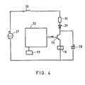
- the current pulse for the coil 16 may be provided by one or more batteries connected in series, said batteries being indicated with the reference number 27 in the circuit diagram of Fig. 4. It is preferable to have the current pulse provided by a capacitor 28 which is shunted with the coil 16. In that case it is possible to gradually load the capacitor, which lengthens the useful life of the battery.
- a diode 29 is connected in series with the capacitor 28 in order to prevent unloading of the capacitor in the rest period of the device, in which the lever 6 is in engagement with the abutment 19.
- the circuit contains IrMhe embodiment shown in switch 30.
- the switch closes, thus switch also being indicated in Fig. 1, and the capcitor is loaded through a resistor 31 of high resistive value.
- This brings in combination with the capacitor a time constant value such that the loading time of the capacitor remains within the so-called first waiting time of the removing apparatus. For it is that if the apparatus is switched on by turning the lever 6 to the right and would one forget to apply the milking set to the cow, the apparatus is again switched off if no milk flows within 90 seconds. Because of this time constant value the battery has to issue only a vey small current pulse when the apparatus is switched off by the control device 32. When issuing the current pulse the capacitor, moreover, will only partially be unloaded, so that after the very first loading for each next loading less energy is required.
- the milking is controlled by an electronic control device 32 connected with the above mentioned milk flow indicator 33.
- suid indicator 33 issues a signal to the control device 32, which in its turn issues a signal to a switching transistor 34.
- this transistor opens or becomes conductive and this results therein that the capacitor 28 can unload with a current pulse through the coil of the solenoid 15, 16.
- the permanent magnet 14 is relsased, the lever 6 rotates to the left until it contacts the abutment 19, the vacuum is connected with the lifting device of the removing apparatus and simultaneously the switch 30 breaks the connection so that no longer current power from the battery 27 is used.
- the use of the switch 30 is not indispensable. After these operations the removing apparatus is again in the rest condition and ready for application to a next cow.
- the material for the valve body 1 a material is used which causes in combination with the material of the valve member 7 very little friction when the valve member moves along the body.
- the material of the valve body e.g. may be celeron which is a synthetic material comprising a fabric reinforced phenol-formaldehyde material and that of the valve member may be ladulene, which is a polyethylene material of high molecular weight.
- a further bore 35 extends in the valve body 1, which is connected with the bore 3 and opens into a chamber 37 which is closed by a plug 36, said chamber 37 being in communication with the connector 5.
- a plate valve 38 e.g. of rubber is provided upstream of the outlet aperture of the channel 35 into the chamber 37, which blade valve operates as a check valve and serves to maintain the vacuum in the removing apparatus when the apparatus is transported from one cow position to another, during which the connection between the hose and the connector 5 is broken.
Landscapes
- Engineering & Computer Science (AREA)
- General Engineering & Computer Science (AREA)
- Physics & Mathematics (AREA)
- Electromagnetism (AREA)
- Mechanical Engineering (AREA)
- External Artificial Organs (AREA)
- Magnetically Actuated Valves (AREA)
Claims (7)
Applications Claiming Priority (2)
| Application Number | Priority Date | Filing Date | Title |
|---|---|---|---|
| NL8600802A NL8600802A (nl) | 1986-03-27 | 1986-03-27 | Magneetklep, in het bijzonder voor een melkstel-afnameapparaat. |
| NL8600802 | 1986-03-27 |
Publications (2)
| Publication Number | Publication Date |
|---|---|
| EP0240060A1 EP0240060A1 (de) | 1987-10-07 |
| EP0240060B1 true EP0240060B1 (de) | 1990-06-06 |
Family
ID=19847789
Family Applications (1)
| Application Number | Title | Priority Date | Filing Date |
|---|---|---|---|
| EP87200499A Expired - Lifetime EP0240060B1 (de) | 1986-03-27 | 1987-03-18 | Elektromagnetisches Ventil, insbesondere für das Abnahmegerät einer Melkmaschine |
Country Status (8)
| Country | Link |
|---|---|
| US (1) | US4715405A (de) |
| EP (1) | EP0240060B1 (de) |
| JP (1) | JPS6334383A (de) |
| CA (1) | CA1269588A (de) |
| DE (1) | DE3763106D1 (de) |
| DK (1) | DK165067C (de) |
| NL (1) | NL8600802A (de) |
| NZ (1) | NZ219743A (de) |
Families Citing this family (2)
| Publication number | Priority date | Publication date | Assignee | Title |
|---|---|---|---|---|
| EP0733648A1 (de) * | 1995-03-23 | 1996-09-25 | Kao Corporation | Verfahren zur Herstellung von Polymerpartikel |
| DE19718454B4 (de) * | 1997-04-30 | 2006-04-13 | Samson Ag | Differenzdruckmeßgerät |
Citations (2)
| Publication number | Priority date | Publication date | Assignee | Title |
|---|---|---|---|---|
| EP0097395A1 (de) * | 1982-06-17 | 1984-01-04 | Kummer Electronics B.V. | Vorrichtung zum Abnehmen des Melkzeuges einer Melkmaschine, insbesondere für Kuhställe |
| EP0217472A1 (de) * | 1985-10-02 | 1987-04-08 | Kummer Electronics B.V. | Vorrichtung zum Abnehmen des Melkzeuges, insbesondere für Kuhställe |
Family Cites Families (6)
| Publication number | Priority date | Publication date | Assignee | Title |
|---|---|---|---|---|
| BE622097A (de) * | ||||
| US1291987A (en) * | 1917-07-11 | 1919-01-21 | Mapel Mfg Company | Valve mechanism. |
| US1400551A (en) * | 1920-07-30 | 1921-12-20 | Henry S Hornbeck | Oscillating valve for pneumatic motors |
| FR1517063A (fr) * | 1967-02-02 | 1968-03-15 | Warner Lambert Pharmaceutical | Distributeur à tiroir à commande électrique |
| DE3033008A1 (de) * | 1979-09-07 | 1981-04-02 | Gretag AG, Regensdorf, Zürich | Notventil |
| US4469304A (en) * | 1980-04-15 | 1984-09-04 | Kah Jr Carl L C | Pulse actuated solenoid valve |
-
1986
- 1986-03-27 NL NL8600802A patent/NL8600802A/nl not_active Application Discontinuation
-
1987
- 1987-03-18 EP EP87200499A patent/EP0240060B1/de not_active Expired - Lifetime
- 1987-03-18 DE DE8787200499T patent/DE3763106D1/de not_active Expired - Fee Related
- 1987-03-20 US US07/028,258 patent/US4715405A/en not_active Expired - Fee Related
- 1987-03-23 DK DK146887A patent/DK165067C/da not_active IP Right Cessation
- 1987-03-24 NZ NZ21974387A patent/NZ219743A/xx unknown
- 1987-03-26 CA CA000533020A patent/CA1269588A/en not_active Expired - Fee Related
- 1987-03-27 JP JP62071929A patent/JPS6334383A/ja active Pending
Patent Citations (2)
| Publication number | Priority date | Publication date | Assignee | Title |
|---|---|---|---|---|
| EP0097395A1 (de) * | 1982-06-17 | 1984-01-04 | Kummer Electronics B.V. | Vorrichtung zum Abnehmen des Melkzeuges einer Melkmaschine, insbesondere für Kuhställe |
| EP0217472A1 (de) * | 1985-10-02 | 1987-04-08 | Kummer Electronics B.V. | Vorrichtung zum Abnehmen des Melkzeuges, insbesondere für Kuhställe |
Also Published As
| Publication number | Publication date |
|---|---|
| NZ219743A (en) | 1989-09-27 |
| EP0240060A1 (de) | 1987-10-07 |
| DK165067B (da) | 1992-10-05 |
| DK165067C (da) | 1993-02-22 |
| DE3763106D1 (de) | 1990-07-12 |
| JPS6334383A (ja) | 1988-02-15 |
| US4715405A (en) | 1987-12-29 |
| DK146887D0 (da) | 1987-03-23 |
| DK146887A (da) | 1987-09-28 |
| NL8600802A (nl) | 1987-10-16 |
| CA1269588A (en) | 1990-05-29 |
Similar Documents
| Publication | Publication Date | Title |
|---|---|---|
| EP0650002B1 (de) | Selbsthaltendes Elektromagnetventil | |
| US4055280A (en) | Diverter valve assembly for ice distribution systems | |
| IT8202910A1 (it) | Valvola elettromagnetica, in particolare per elettrodomestici | |
| GB2101721A (en) | Joystick control means | |
| US3134404A (en) | Electro-magnetically operated floating armature valves | |
| GB2206675A (en) | Electromagnetically-actuatable three-way/two-position directional control valve | |
| US4723755A (en) | Two-port solenoid valve | |
| EP0240060B1 (de) | Elektromagnetisches Ventil, insbesondere für das Abnahmegerät einer Melkmaschine | |
| US7066049B2 (en) | Wear-free accelerator pedal kick-down switch | |
| US5915668A (en) | Fail safe valve actuator | |
| US4376896A (en) | Switching assembly | |
| JP2564817B2 (ja) | 電磁弁装置 | |
| CA1216494A (en) | Electrically actuated valve assembly | |
| GB2161875A (en) | Automatic vehicle brake control system e g for hill starts | |
| EP0803652A3 (de) | Umgossener Datenbus mit integriertem Schalter | |
| US4366944A (en) | Magnetically actuated pilot valve | |
| GB1066777A (en) | Improvements relating to fluid control valves | |
| US4539862A (en) | Detent hold and release mechanism | |
| US3814133A (en) | Solenoid operated compressed air valve | |
| US4349045A (en) | Magnetically actuated pilot valve | |
| CA2618037A1 (en) | System for opening and/or closing an inlet valve and/or an outlet valve of a liquid container | |
| DE19748374C1 (de) | Vakuumspanneinrichtung | |
| US4964424A (en) | Pneumatic valve assembly for controlling a stream of compressed air | |
| GB2051481A (en) | Electrical switch | |
| JPH08121636A (ja) | マイクロバルブ |
Legal Events
| Date | Code | Title | Description |
|---|---|---|---|
| PUAI | Public reference made under article 153(3) epc to a published international application that has entered the european phase |
Free format text: ORIGINAL CODE: 0009012 |
|
| AK | Designated contracting states |
Kind code of ref document: A1 Designated state(s): DE FR GB IT NL SE |
|
| 17P | Request for examination filed |
Effective date: 19880329 |
|
| 17Q | First examination report despatched |
Effective date: 19890223 |
|
| GRAA | (expected) grant |
Free format text: ORIGINAL CODE: 0009210 |
|
| AK | Designated contracting states |
Kind code of ref document: B1 Designated state(s): DE FR GB IT NL SE |
|
| REF | Corresponds to: |
Ref document number: 3763106 Country of ref document: DE Date of ref document: 19900712 |
|
| ITF | It: translation for a ep patent filed | ||
| ET | Fr: translation filed | ||
| PLBE | No opposition filed within time limit |
Free format text: ORIGINAL CODE: 0009261 |
|
| STAA | Information on the status of an ep patent application or granted ep patent |
Free format text: STATUS: NO OPPOSITION FILED WITHIN TIME LIMIT |
|
| ITTA | It: last paid annual fee | ||
| 26N | No opposition filed | ||
| PGFP | Annual fee paid to national office [announced via postgrant information from national office to epo] |
Ref country code: SE Payment date: 19930310 Year of fee payment: 7 |
|
| PGFP | Annual fee paid to national office [announced via postgrant information from national office to epo] |
Ref country code: GB Payment date: 19930317 Year of fee payment: 7 Ref country code: FR Payment date: 19930317 Year of fee payment: 7 |
|
| PGFP | Annual fee paid to national office [announced via postgrant information from national office to epo] |
Ref country code: DE Payment date: 19930323 Year of fee payment: 7 |
|
| PGFP | Annual fee paid to national office [announced via postgrant information from national office to epo] |
Ref country code: NL Payment date: 19930331 Year of fee payment: 7 |
|
| PG25 | Lapsed in a contracting state [announced via postgrant information from national office to epo] |
Ref country code: GB Effective date: 19940318 |
|
| PG25 | Lapsed in a contracting state [announced via postgrant information from national office to epo] |
Ref country code: SE Free format text: LAPSE BECAUSE OF NON-PAYMENT OF DUE FEES Effective date: 19940319 |
|
| PG25 | Lapsed in a contracting state [announced via postgrant information from national office to epo] |
Ref country code: NL Effective date: 19941001 |
|
| GBPC | Gb: european patent ceased through non-payment of renewal fee |
Effective date: 19940318 |
|
| NLV4 | Nl: lapsed or anulled due to non-payment of the annual fee | ||
| PG25 | Lapsed in a contracting state [announced via postgrant information from national office to epo] |
Ref country code: FR Effective date: 19941130 |
|
| PG25 | Lapsed in a contracting state [announced via postgrant information from national office to epo] |
Ref country code: DE Effective date: 19941201 |
|
| REG | Reference to a national code |
Ref country code: FR Ref legal event code: ST |
|
| EUG | Se: european patent has lapsed |
Ref document number: 87200499.9 Effective date: 19941010 |
|
| PG25 | Lapsed in a contracting state [announced via postgrant information from national office to epo] |
Ref country code: IT Free format text: LAPSE BECAUSE OF NON-PAYMENT OF DUE FEES;WARNING: LAPSES OF ITALIAN PATENTS WITH EFFECTIVE DATE BEFORE 2007 MAY HAVE OCCURRED AT ANY TIME BEFORE 2007. THE CORRECT EFFECTIVE DATE MAY BE DIFFERENT FROM THE ONE RECORDED. Effective date: 20050318 |