EP0239680B1 - Heat pump - Google Patents
Heat pump Download PDFInfo
- Publication number
- EP0239680B1 EP0239680B1 EP86201755A EP86201755A EP0239680B1 EP 0239680 B1 EP0239680 B1 EP 0239680B1 EP 86201755 A EP86201755 A EP 86201755A EP 86201755 A EP86201755 A EP 86201755A EP 0239680 B1 EP0239680 B1 EP 0239680B1
- Authority
- EP
- European Patent Office
- Prior art keywords
- vapor
- compressor
- liquid
- steam
- heat
- Prior art date
- Legal status (The legal status is an assumption and is not a legal conclusion. Google has not performed a legal analysis and makes no representation as to the accuracy of the status listed.)
- Expired
Links
Images





Classifications
-
- F—MECHANICAL ENGINEERING; LIGHTING; HEATING; WEAPONS; BLASTING
- F25—REFRIGERATION OR COOLING; COMBINED HEATING AND REFRIGERATION SYSTEMS; HEAT PUMP SYSTEMS; MANUFACTURE OR STORAGE OF ICE; LIQUEFACTION SOLIDIFICATION OF GASES
- F25B—REFRIGERATION MACHINES, PLANTS OR SYSTEMS; COMBINED HEATING AND REFRIGERATION SYSTEMS; HEAT PUMP SYSTEMS
- F25B1/00—Compression machines, plants or systems with non-reversible cycle
- F25B1/10—Compression machines, plants or systems with non-reversible cycle with multi-stage compression
-
- F—MECHANICAL ENGINEERING; LIGHTING; HEATING; WEAPONS; BLASTING
- F25—REFRIGERATION OR COOLING; COMBINED HEATING AND REFRIGERATION SYSTEMS; HEAT PUMP SYSTEMS; MANUFACTURE OR STORAGE OF ICE; LIQUEFACTION SOLIDIFICATION OF GASES
- F25B—REFRIGERATION MACHINES, PLANTS OR SYSTEMS; COMBINED HEATING AND REFRIGERATION SYSTEMS; HEAT PUMP SYSTEMS
- F25B11/00—Compression machines, plants or systems, using turbines, e.g. gas turbines
- F25B11/02—Compression machines, plants or systems, using turbines, e.g. gas turbines as expanders
-
- F—MECHANICAL ENGINEERING; LIGHTING; HEATING; WEAPONS; BLASTING
- F25—REFRIGERATION OR COOLING; COMBINED HEATING AND REFRIGERATION SYSTEMS; HEAT PUMP SYSTEMS; MANUFACTURE OR STORAGE OF ICE; LIQUEFACTION SOLIDIFICATION OF GASES
- F25B—REFRIGERATION MACHINES, PLANTS OR SYSTEMS; COMBINED HEATING AND REFRIGERATION SYSTEMS; HEAT PUMP SYSTEMS
- F25B2400/00—Component parts or details not otherwise provided for in this subclass
- F25B2400/13—Economisers
-
- F—MECHANICAL ENGINEERING; LIGHTING; HEATING; WEAPONS; BLASTING
- F25—REFRIGERATION OR COOLING; COMBINED HEATING AND REFRIGERATION SYSTEMS; HEAT PUMP SYSTEMS; MANUFACTURE OR STORAGE OF ICE; LIQUEFACTION SOLIDIFICATION OF GASES
- F25B—REFRIGERATION MACHINES, PLANTS OR SYSTEMS; COMBINED HEATING AND REFRIGERATION SYSTEMS; HEAT PUMP SYSTEMS
- F25B2400/00—Component parts or details not otherwise provided for in this subclass
- F25B2400/23—Separators
Definitions
- the present invention relates to a heat pump.
- Compression-type heat pumps comprise an evaporator which absorbs heat energy from a lower temperature heat source, a compressor which adiabatically compresses the working fluid vapor evaporated by the evaporator, a condenser which provides heat energy to a higher temperature heat sink by condensation of heat medium vapor having a temperature and a pressure raised by the compressor, and an expansion valve which flashes and expands the heat medium condensate formed in the condenser, wherein an arrangement is made such that from the expansion valve, the working fluid is sent back to the evaporator.
- Displacement compressors are simple in structure and, in addition, can provide a constant pressure ratio even under partial loading conditions by changing the number of rotation, so that they are suitably useful in or for heat pumps or heat pump systems.
- the volume of fluid that they can deal with is relatively limited and also their volume efficiency tends to lower under partial loading conditions, whereby it has been difficult to realize a scale-up of heat pumps with use of a displacement compressor.
- centrifugal-type compressors characteristically have a large capacity of fluid compression in spite of their being relatively limited in size.
- the power required for driving the compressor becomes greater and the coefficient of performance (the transferred heat/the power input for the driving of the compressor - hereinafter referred to as COP -) becomes lowered.
- a vapor-liquid separator is arranged between the condenser and the expansion valve for separating a working fluid introduced by the condenser and an expansion turbine driven by the vapor separated by the vapor-liquid separator is drivingly connected to the compressor.
- the expanded vapor is then directly returned to the evaporator of the heat pump.
- the present invention reduces the power required for the driving of the compressor by means of the features set forth in claim 1.
- a heat pump provided with a vapor-liquid separator and an expansion turbine as disclosed in US-A 3 367 125 is improved by causing the expansion turbine to expand the vapor to a pressure below the evaporation pressure in the evaporator and by inserting in the return path of the expanded vapor to the evaporator a condenser for cooling and liquefying the vapor and a pump for compressing and cycling the resulting liquid to the evaporator. It has been experienced that a satisfactorily great power can be recovered.
- the present invention is operated to heat the vapor separated by the vapor-liquid separator by a superheater utilizing for its heat source the condensate generated in the condenser, and supply vapor to the expansion turbine in the form of superheated vapor. According to this, a satisfactorily great expansion ratio can be obtained of the vapor in the expansion turbine to effectively enhance the efficiency of the energy recovery.
- the degree of dryness (or the quality) of saturated vapor at the turbine outlet tends to become excessively low, and then to take into consideration the operation efficiency and the structural designing, it is infeasible to obtain a satisfactorily high pressure ratio.
- the invention is characterized in that it operates a self heat exchange. In this manner, it is feasible to set the turbine expansion ratio at a raised value while keeping the quality of the vapor at the turbine outlet above a lower limit value and improve the recovery of power by the expansion turbine, so that the efficiency (COP) of the heat pump can be enhanced.
- the invention makes use of the heat medium liquid separated by the vapor-liquid separator as atomized liquid to be sprayed to the superheated vapor in the process of being compressed in the compressor. According to this method, the amount of condensate in the condensor is increased, so that the amount of vapor to be flashed by the expansion valve, too, is increased, whereby the recovery of power for the driving of the turbine is improved to enhance the operation efficiency of the heat pump.
- the heat medium vapor compressed in the compressor is guided into a desuperheater to reduce the degree of superheat of the vapor, and in doing this, the liquid separated by the vapor-liquid separator is atomized and sprayed into the desuperheater. According to this, the quantity of vapor to be flashed can be increased for same reasons as above, so that the recovery of power by the turbine can be improved to enhance the COP.
- the heat pump in accord with a further embodiment of the invention is made including at a stage preceding to the displacement compressor a turbo compressor driven by the power recovery turbine so that the heat medium vapor is increased in its density and only then supplied into the displacement compressor.
- the heat medium vapor can be supplied to the displacement compressor after its density is increased by the turbo compressor, therefore it is advantageously possible to increase the volume of vapor that the displacement compressor can deal with or, in other words, it is possible to reduce the size of the displacement compressor accordingly and curtail the production cost of the compressor.
- essentially the turbo compressor is relatively small in size, and the advantage due to the reduction in the production cost as above well exceeds a disadvantage due to the incorporation of a turbo compressor, if made as above.
- a vapor-liquid separator for separating the heat medium condensate introduced from the condenser through the expansion valve into vapor and liquid and an expansion turbine driven by the heat medium vapor separated by the separator, and an arrangement is made such that the turbo compressor disposed at a preceeding stage to the displacement compressor as above is driven by the expansion turbine.
- the expansion turbine comprising a velocity type turbine as above, the speed of rotation of the compressor and that of the turbine can be made to with ease correspond to each other.
- the invention provides such a heat pump which can exhibit a satisfactorily high COP in practical applications of the pump with use of a great temperature difference, and the invention is extremely useful for industrial applications.
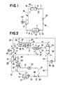
- this compression heat pump comprises an evaporator 11 for absorbing heat energy from a low temperature heat source, a compressor 17 for adiabatically compressing a heat medium steam from the evaporator 11, a condenser 19 for providing the heat energy to a higher temperature heat sink from the heat medium whose temperature and pressure are elevated by the compressor 17, and an expansion valve 22 for flushing and expanding the heat medium liquefied in the condenser 19.
- the heat medium is returned from the expansion valve 22 to the evaporator 11.
- Fig. 2 is a diagram of the heat pump in accordance with the present invention.
- the heat medium supplied from a piping arrangement 12 to an evaporator 11 absorbs heat from a low temperature heat source 13 and evaporates and turns into steam S i , which is introduced into a foreside stage compressor 15 through another piping arrangement 14.
- the steam Si is compressed into an intermediate pressure steam S 2 by the compressor 15 and is introduced to another compressor 17 through a piping 16.
- the steam is compressed by the compressor 17 to a high temperature and high pressure steam Ss, which is supplied to a desuperheater 37 disposed at an intermediate portion of a piping 18.
- the desuperheater 37 has a nozzle 38, and the superheated steam S ⁇ makes direct heat exchange with a liquid heat medium atomized from this nozzle 38, and is cooled near to saturation and is changed to a substantially saturated steam S 4 .
- This saturated steam S 4 is supplied to a condenser 19 through the piping 18. Since the heat medium atomized from the nozzle 38 evaporates and turns into a steam, too, the quantity of steam introduced into the condenser 19 increases.
- the heat medium is atomized and sprayed into the compressor 17 through a pipe 36.
- the foreside stage compressor 15 is connected to a later-appearing expansion turbine 28 by a shaft 26, thereby forming a steam supercharger 25.
- the heat energy of the saturated steam S 4 is supplied to the high temperature heat sink 20 and is condensed.
- the heat medium liquid L condensed in the condenser 19 makes indirect heat exchange with a later-appearing steam 5 5 in a superheater 41 disposed at an intermediate portion of the piping 21 and is then expanded by the expansion valve 22. Thereafter, the heat medium liquid L is separated into a liquid L i and a steam 8 5 by a vapor-liquid separator 23.
- the steam S 5 is introduced into the superheater 41 through a piping 24, makes heat exchange with the heat medium liquid L derived from the condenser 19 and is heated to a superheated steam Se.
- This superheated steam Ss is introduced into the expansion turbine 28 for driving the foreside stage compressor 15 through a conduit 27.
- the steam Ss is expanded to a pressure below that of the evaporator and preferably, to vacuum, and a steam S 7 derived therefrom is sent to a condenser 30 through a piping arrangement 29, where it is condensed to a low temperature liquid L 2 .
- the heat medium liquid atomized from m of the compressor 17 and n of the desuperheater 37 it is possible to use the heat medium liquid recirculated from the piping 12 to the evaporator 11 of this system or the heat medium liquid L derived from the condenser 19 or the heat medium liquid Li derived from the vapor-liquid separator 23, but it is recommended to use the heat medium liquid L 1 in the present invention.
- the pressure of the heat liquid medium is raised by the pump 35 disposed at the intermediate portion of the piping 36 branched from the piping 34 and the heat medium liquid is then atomized and injected into the compressor 17 from a nozzle (not shown) at the tip of the pipe 36.
- the heat medium liquid is atomized and injected from the nozzle 38 of the desuperheater 37 from the piping 39 branched from the piping 36.
- the reference numeral 40 represents a motor and 46 a pressure control valve.
- Fig. 4 shows a fundamental system for converting the internal energy of the condensate in the condenser 19 to the power.
- the condensate is flashed by the expansion valve 22 and the resulting steam is supplied to the steam expansion turbine 28.
- the resulting power is used as part of the driving force for the compressor 17.
- Some conventional expansion turbines assembled in the heat pump are based upon the concept of expanding the steam to the evaporation pressure of the evaporator such as a total flow expander but they supply the resulting steam as such to the compressor.
- the resulting steam is expanded to a pressure below the evaporation pressure and preferably, to vacuum, and sufficiently great power is recovered.
- This is the characterizing feature of the present invention. Incidentally, it is necessary to condense the expanded steam by the condenser 30 and to raise its pressure to the evaporation pressure by the pump 32, but the power necessary therefor can be neglected.
- the compressor 17 and the expansion turbine 28 are directly connected by the shaft 47.
- Fig. 5 is a Morrie diagram which explains the operation of Fig. 4 and symbols a, b, c, e, f, f, f", g and h correspond to the respective positions in Fig. 5.
- Fig. 6 is a diagram of a system accomplishing the concept of Fig. 4 as an actual system, wherein the compressor 17 is a displacement compressor.
- the expansion turbine 28 is a steam turbine which is a turbo machine and the compressor 15 to be driven by the steam turbine is a turbo compressor which is also a turbo machine, and they are directly connected by the shaft 26, thereby forming a steam turbocharger 25. Since the turbo machine rotates at a high speed, it is small in size and since it super- charges the displacement compressor, the latter can be made compact in size. Therefore, the cost of production can be reduced.
- Fig. 8 is a Morrie diagram of the heat pump system in accordance with the present invention.
- the positions represented by symbols a, b, b', c, e, e', f, f, f", f", g and h represent the same positions as those in Fig. 7.
- Fig. 10 is a system flow diagram when the recovered power of the present invention exceeds the power necessary for compressing the steam. In such a case, some start means are necessary and the heat pump operates without external power. In case of the system performance at a condensation temperature of 300 ° C as shown in Fig. 11, the system shown in Fig. 10 can be operated at an evaporation temperature of above 250 ° C and since there is no external power in this case, the theoretical COP becomes indefinite.
- the superheated steam S 3 having a high temperature and a high pressure which is compressed by the compressor 17 is supplied to the desuperheater 37 disposed at an intermediate portion of the piping 18.
- This desuperheater 37 has the nozzle 38, and the liquid heat medium atomized from this nozzle 38 cools the superheated steam S 3 into saturation.
- the saturated steam S 4 is supplied to the condenser 19 through the piping 18.
- the heat medium atomized from the nozzle 38 turns into the steam, too, and is therefore supplied to the condenser 19, where the quantity of steam thus increases.
- the flash steam quantity increase and contributes to the increase in the output of the expansion turbine 28. Since the output of the expansion turbine 28 is thus increased, the compression ratio of the foreside stage compressor 15 increases so that the power necessary for driving the motor 40 for driving the compressor 17 can be reduced.
- Fig. 13 is a Morrie diagram of the heat pump system in accordance with the present invention, and symbols a, b, c, e, f, f, f", g and h represent the same conditions at the positions represented by the same reference numerals in Fig. 12.
- Fig. 14 shows a case where intermediate cooling is effected in order to reduce the compressor power.
- the flash liquid Li is injected into the cooler 50 disposed at the intermediate portion between the compressors 17a and 17b in order to reduce the temperature by direct heat exchange and evaporation. Since the flash steam quantity increases for the same reason as shown in Fig. 12, the recovered power increases and the COP increases, too.
- Fig. 15 is a Morrie diagram in the compression stroke when intermediate cooling is effected.
- the present invention uses a displacement compressor as the compressor 17, injects the liquid into the steam during its compression stroke, controls the compression temperature by the evaporation of the steam and brings the compression close to isothermal compression.
- the liquid-atomizing type steam compressor 1 includes a piston 3 which reciprocates inside a cylinder 2 and a suction valve 5, a delivery valve 6 and a liquid atomizing valve 4 that are disposed at a cylinder head 2a.
- the liquid atomizing valve 4 is specifically disposed in order to practise the present invention. Its operation timing is regulated so that when the piston 3 moves to the right and compresses the steam, the valve 4 atomizes the cooling liquid into the cylinder 2.
- the opening and closing timing of the liquid atomizing valve 4 is regulated so that it stops atomization of the cooling liquid when the pressure inside the cylinder 2 reaches a predetermined value.
- liquid injection into a compressor has been known in the past, but the present invention is characterized in that the temperature control is effected while the steam is in the superheated state, makes direct heat exchange with the liquid and evaporates.
- the curve M represents the increase of enthalpy of the steam with respect to the piston stroke x in the conventional steam compression method by adiabatic compression while the curve N represents that of the liquid atomizing system according to the present invention.
- curve A-B represents a saturated liquid line while curve C-D represents a saturated steam line.
- a saturated steam H [60 ° C, 19.9 kPa (0.203 ata)] is compressed to a steam I [110 ° C, 27.5 kPa (0.28 ata)] and turned into a superheated steam.
- the cooling liquid W exchanges heat with the superheated steam from a point [85 ° C, 27.5 kPa (0.28 ata)] on the curve A-B and evaporates, thereby cooling the steam S.
- the compression takes a route (1) of the curve I-J and the steam becomes 175 ° C, 2826 kJ/kg (675 Kcal/kg) at the final stage.
- the curve I-J and the curve C-D have the temperature difference of 25 ° C for the same pressure.
Landscapes
- Engineering & Computer Science (AREA)
- Physics & Mathematics (AREA)
- Mechanical Engineering (AREA)
- Thermal Sciences (AREA)
- General Engineering & Computer Science (AREA)
- Engine Equipment That Uses Special Cycles (AREA)
Description
- The present invention relates to a heat pump.
- Compression-type heat pumps comprise an evaporator which absorbs heat energy from a lower temperature heat source, a compressor which adiabatically compresses the working fluid vapor evaporated by the evaporator, a condenser which provides heat energy to a higher temperature heat sink by condensation of heat medium vapor having a temperature and a pressure raised by the compressor, and an expansion valve which flashes and expands the heat medium condensate formed in the condenser, wherein an arrangement is made such that from the expansion valve, the working fluid is sent back to the evaporator.
- Where the output required is relatively small (for example up to about 500 kw), use is made as the compressor of one of displacement compressors such as reciprocating displacement compressors, rotating displacement compressors (including screw type ones) and so forth. Displacement compressors are simple in structure and, in addition, can provide a constant pressure ratio even under partial loading conditions by changing the number of rotation, so that they are suitably useful in or for heat pumps or heat pump systems. However, the volume of fluid that they can deal with is relatively limited and also their volume efficiency tends to lower under partial loading conditions, whereby it has been difficult to realize a scale-up of heat pumps with use of a displacement compressor.
- Then, where a relatively large output is required, use is made primarily of a centrifugal-type compressor since centrifugal-type compressors characteristically have a large capacity of fluid compression in spite of their being relatively limited in size.
- Whereas conventionally heat pumps have been utilized mainly for air conditioning purposes, lately it has been increasingly attempted to make use of heat pumps also in various industrial fields by elevating the operation or working temperature and enhancing the operation efficiency of the heat pump. The present invention is in line with such tendency in the art and seeks for effectively elevating the operation or working temperature of the heat pump up to about 300° C, which conventionally has been about 100° C at the highest, and providing a heat pump which can satisfactorily stand practical uses even if a large extent of rise is made of the temperature so as to largely broaden the field of application or use of heat pumps.
- Generally, as the temperature difference to be set between a (lower temperature) heat source and a heat sink is greater, the power required for driving the compressor becomes greater and the coefficient of performance (the transferred heat/the power input for the driving of the compressor - hereinafter referred to as COP -) becomes lowered.
- Thus, although there have been attempts made to utilize heat pumps in industrial fields, it is difficult to attain a sufficient effect of energy saving in addition to the difficulty that it is costly to install a heat pump, and in many instances no high effect has been provided of the economical advantage and the investment, with the result that today still limited are the fields in which heat pumps are put for an actual or a practical use.
- According to US-A 3 367 125 a vapor-liquid separator is arranged between the condenser and the expansion valve for separating a working fluid introduced by the condenser and an expansion turbine driven by the vapor separated by the vapor-liquid separator is drivingly connected to the compressor. The expanded vapor is then directly returned to the evaporator of the heat pump.
- It is a first object of the present invention to realize an improvement in or relating to the operation efficiency of heat pumps of the prior art.
- It is a second object of the invention to enhance the capacity of heat pumps by increasing the volume of fluid that a displacement compressor in or of the heat pump can deal with, and thereby reduce the production cost of plants.
- In order to accomplish the first object of the invention or to improve the COP that is the most important one of performance indices of the heat pump, the present invention reduces the power required for the driving of the compressor by means of the features set forth in
claim 1. Particularly, a heat pump provided with a vapor-liquid separator and an expansion turbine as disclosed in US-A 3 367 125 is improved by causing the expansion turbine to expand the vapor to a pressure below the evaporation pressure in the evaporator and by inserting in the return path of the expanded vapor to the evaporator a condenser for cooling and liquefying the vapor and a pump for compressing and cycling the resulting liquid to the evaporator. It has been experienced that a satisfactorily great power can be recovered. - According to a further embodiment of the present invention, it is operated to heat the vapor separated by the vapor-liquid separator by a superheater utilizing for its heat source the condensate generated in the condenser, and supply vapor to the expansion turbine in the form of superheated vapor. According to this, a satisfactorily great expansion ratio can be obtained of the vapor in the expansion turbine to effectively enhance the efficiency of the energy recovery.
- Generally, when saturated vapor is expanded by the expansion turbine, the degree of dryness (or the quality) of saturated vapor at the turbine outlet tends to become excessively low, and then to take into consideration the operation efficiency and the structural designing, it is infeasible to obtain a satisfactorily high pressure ratio. Thus, according to the present invention, it is proposed to superheat the saturated vapor at the inlet of the expansion turbine, suppress the degree of wetness of the vapor at the outlet of the turbine and, in addition, make use of the condensate before being flashed by the expansion valve, for the heat source for the superheating. Therefore, the invention is characterized in that it operates a self heat exchange. In this manner, it is feasible to set the turbine expansion ratio at a raised value while keeping the quality of the vapor at the turbine outlet above a lower limit value and improve the recovery of power by the expansion turbine, so that the efficiency (COP) of the heat pump can be enhanced.
- As a further preferred means for the energy recovery in the heat pump, the invention makes use of the heat medium liquid separated by the vapor-liquid separator as atomized liquid to be sprayed to the superheated vapor in the process of being compressed in the compressor. According to this method, the amount of condensate in the condensor is increased, so that the amount of vapor to be flashed by the expansion valve, too, is increased, whereby the recovery of power for the driving of the turbine is improved to enhance the operation efficiency of the heat pump.
- According to the present invention, further, the heat medium vapor compressed in the compressor is guided into a desuperheater to reduce the degree of superheat of the vapor, and in doing this, the liquid separated by the vapor-liquid separator is atomized and sprayed into the desuperheater. According to this, the quantity of vapor to be flashed can be increased for same reasons as above, so that the recovery of power by the turbine can be improved to enhance the COP.
- In order to accomplish the second object of the invention, the heat pump in accord with a further embodiment of the invention is made including at a stage preceding to the displacement compressor a turbo compressor driven by the power recovery turbine so that the heat medium vapor is increased in its density and only then supplied into the displacement compressor. With this heat pump, the heat medium vapor can be supplied to the displacement compressor after its density is increased by the turbo compressor, therefore it is advantageously possible to increase the volume of vapor that the displacement compressor can deal with or, in other words, it is possible to reduce the size of the displacement compressor accordingly and curtail the production cost of the compressor. In this connection, further, essentially the turbo compressor is relatively small in size, and the advantage due to the reduction in the production cost as above well exceeds a disadvantage due to the incorporation of a turbo compressor, if made as above.
- In accord with the present invention, further, there are provided a vapor-liquid separator for separating the heat medium condensate introduced from the condenser through the expansion valve into vapor and liquid and an expansion turbine driven by the heat medium vapor separated by the separator, and an arrangement is made such that the turbo compressor disposed at a preceeding stage to the displacement compressor as above is driven by the expansion turbine.
- By making the expansion turbine comprising a velocity type turbine as above, the speed of rotation of the compressor and that of the turbine can be made to with ease correspond to each other.
- As will become more clearly understood from considering the bolow recited description of specific embodiments of the invention, the invention provides such a heat pump which can exhibit a satisfactorily high COP in practical applications of the pump with use of a great temperature difference, and the invention is extremely useful for industrial applications.
- Fig. 1 is a system diagram of a conventional heat pump;
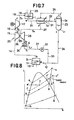
- Fig. 2 is a system diagram of a heat pump in accordance with the present invention;
- Fig. 3 is a Morrie diagram in the heat pump shown in Fig. 2;
- Fig. 4 is a system diagram, taken for illustration of the function of the heat pump according to the present invention;
- Fig. 5 is a Morrie diagram of the heat pump shown in Fig. 4;
- Figs. 6 and 7 are system diagrams, illustrative of the function of the heat pump according to the present invention;
- Fig. 8 is a Morrie diagram of the heat pump shown in Fig. 7;
- Fig. 9 is a Morrie diagram, representing the operation of a turbine unit;
- Fig. 10 is a system diagram of a further heat pump according to the present invention;
- Fig. 11 is a diagram, showing the relation between the COP and the evaporation temperature;
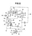
- Fig. 12 is a system diagram of a further heat pump of the present invention;
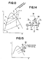
- Fig. 13 is a Morrie diagram of the heat pump of Fig. 12;
- Fig. 14 is a schematic block diagram of a compressor having an intermediate cooler;
- Fig. 15 is a Morrie diagram of the compressor shown in Fig. 14;
- Fig. 16(A) is a schematic view of a compressor used for practising the gas compression method according to the present invention;
- Fig. 16(B) is a diagram, showing the relation between enthalpy and the piston stroke; and
- Fig. 17 is a diagram of steam in the vapor compression process in the compressor according to the present invention and in a conventional compressor, respectively.
- A conventional heat pump system will be first described before the present invention is described in detail.
- As shown in Fig. 1, this compression heat pump comprises an
evaporator 11 for absorbing heat energy from a low temperature heat source, acompressor 17 for adiabatically compressing a heat medium steam from theevaporator 11, acondenser 19 for providing the heat energy to a higher temperature heat sink from the heat medium whose temperature and pressure are elevated by thecompressor 17, and anexpansion valve 22 for flushing and expanding the heat medium liquefied in thecondenser 19. The heat medium is returned from theexpansion valve 22 to theevaporator 11. - Thus, the conventional heat pump is not free from the problems described already.
- Next, the heat pump in accordance with the present invention will be described.
- Fig. 2 is a diagram of the heat pump in accordance with the present invention. The heat medium supplied from a
piping arrangement 12 to anevaporator 11 absorbs heat from a lowtemperature heat source 13 and evaporates and turns into steam Si, which is introduced into aforeside stage compressor 15 through anotherpiping arrangement 14. The steam Si is compressed into an intermediate pressure steam S2 by thecompressor 15 and is introduced to anothercompressor 17 through apiping 16. The steam is compressed by thecompressor 17 to a high temperature and high pressure steam Ss, which is supplied to adesuperheater 37 disposed at an intermediate portion of apiping 18. Thedesuperheater 37 has anozzle 38, and the superheated steam Sε makes direct heat exchange with a liquid heat medium atomized from thisnozzle 38, and is cooled near to saturation and is changed to a substantially saturated steam S4. This saturated steam S4 is supplied to acondenser 19 through thepiping 18. Since the heat medium atomized from thenozzle 38 evaporates and turns into a steam, too, the quantity of steam introduced into thecondenser 19 increases. - The heat medium is atomized and sprayed into the
compressor 17 through apipe 36. Theforeside stage compressor 15 is connected to a later-appearingexpansion turbine 28 by ashaft 26, thereby forming asteam supercharger 25. - In the
condenser 19, the heat energy of the saturated steam S4 is supplied to the hightemperature heat sink 20 and is condensed. The heat medium liquid L condensed in thecondenser 19 makes indirect heat exchange with a later-appearingsteam 55 in asuperheater 41 disposed at an intermediate portion of the piping 21 and is then expanded by theexpansion valve 22. Thereafter, the heat medium liquid L is separated into a liquid Li and a steam 85 by a vapor-liquid separator 23. - The steam S5 is introduced into the
superheater 41 through a piping 24, makes heat exchange with the heat medium liquid L derived from thecondenser 19 and is heated to a superheated steam Se. This superheated steam Ss is introduced into theexpansion turbine 28 for driving theforeside stage compressor 15 through aconduit 27. In theexpansion turbine 28, the steam Ss is expanded to a pressure below that of the evaporator and preferably, to vacuum, and a steam S7 derived therefrom is sent to acondenser 30 through apiping arrangement 29, where it is condensed to a low temperature liquid L2. After its pressure is raised by apump 32 disposed at an intermediate portion of apiping 31, it is mixed by amixer 45 with the liquid L1 subjected to the vapor-liquid separation in the vapor-liquid separator 23 through a piping 31, and is thereafter recirculated to theevaporator 11 through thepiping 12. - As the heat medium liquid atomized from m of the
compressor 17 and n of thedesuperheater 37, it is possible to use the heat medium liquid recirculated from the piping 12 to theevaporator 11 of this system or the heat medium liquid L derived from thecondenser 19 or the heat medium liquid Li derived from the vapor-liquid separator 23, but it is recommended to use the heat medium liquid L1 in the present invention. As shown in Fig. 2, the pressure of the heat liquid medium is raised by thepump 35 disposed at the intermediate portion of the piping 36 branched from the piping 34 and the heat medium liquid is then atomized and injected into thecompressor 17 from a nozzle (not shown) at the tip of thepipe 36. Similarly, the heat medium liquid is atomized and injected from thenozzle 38 of thedesuperheater 37 from the piping 39 branched from thepiping 36. In the drawings, thereference numeral 40 represents a motor and 46 a pressure control valve. - Since the system shown in Fig. 2 contains all the necessary constituent elements of the present invention, the function of each constituent element will be described.
- Incidentally, like reference numerals are used in all the drawings to identify like constituent elements as in Fig. 2. Fig. 4 shows a fundamental system for converting the internal energy of the condensate in the
condenser 19 to the power. The condensate is flashed by theexpansion valve 22 and the resulting steam is supplied to thesteam expansion turbine 28. The resulting power is used as part of the driving force for thecompressor 17. Some conventional expansion turbines assembled in the heat pump are based upon the concept of expanding the steam to the evaporation pressure of the evaporator such as a total flow expander but they supply the resulting steam as such to the compressor. In accordance with the present invention, the resulting steam is expanded to a pressure below the evaporation pressure and preferably, to vacuum, and sufficiently great power is recovered. This is the characterizing feature of the present invention. Incidentally, it is necessary to condense the expanded steam by thecondenser 30 and to raise its pressure to the evaporation pressure by thepump 32, but the power necessary therefor can be neglected. Thecompressor 17 and theexpansion turbine 28 are directly connected by theshaft 47. - Fig. 5 is a Morrie diagram which explains the operation of Fig. 4 and symbols a, b, c, e, f, f, f", g and h correspond to the respective positions in Fig. 5.
- Fig. 6 is a diagram of a system accomplishing the concept of Fig. 4 as an actual system, wherein the
compressor 17 is a displacement compressor. Theexpansion turbine 28 is a steam turbine which is a turbo machine and thecompressor 15 to be driven by the steam turbine is a turbo compressor which is also a turbo machine, and they are directly connected by theshaft 26, thereby forming asteam turbocharger 25. Since the turbo machine rotates at a high speed, it is small in size and since it super- charges the displacement compressor, the latter can be made compact in size. Therefore, the cost of production can be reduced. - As shown in Fig. 7, in the
superheater 41, the condensed hot water moves from e to e' and in this instance, emits the heat and heats the flashed steam. Therefore, the steam shifts from the saturated state f" to the superheated state f". Since the steam is introduced into theturbine 28 in this superheated state, a greater expansion ratio can be secured without causing an excessive drop of the quality (dryness) of the steam at the turbine outlet. - Namely, in Fig. 9, it will be assumed that the saturated steam f" having a pressure Pi is adiabatically expanded in the turbine and the quality (dryness) x at the turbine outlet is 0.85. Then, the steam is expanded to g' and a pressure P2 shown in Fig. 9. The thermal drop in this case is represented by AiA. If the steam is superheated at the same pressure PjA (f), the steam is expanded to a pressure P3 when it is expanded to the same quality (dryness).
- Fig. 8 is a Morrie diagram of the heat pump system in accordance with the present invention. The positions represented by symbols a, b, b', c, e, e', f, f, f", f", g and h represent the same positions as those in Fig. 7.
- Fig. 10 is a system flow diagram when the recovered power of the present invention exceeds the power necessary for compressing the steam. In such a case, some start means are necessary and the heat pump operates without external power. In case of the system performance at a condensation temperature of 300°C as shown in Fig. 11, the system shown in Fig. 10 can be operated at an evaporation temperature of above 250°C and since there is no external power in this case, the theoretical COP becomes indefinite.
- On the other hand, in order to improve the performance of the heat pump, it is necessary according to the present invention to effect power recovery, and at the same time, to take into consideration a reduction of the compression power itself.
- As shown in Fig. 12, the superheated steam S3 having a high temperature and a high pressure which is compressed by the
compressor 17 is supplied to thedesuperheater 37 disposed at an intermediate portion of thepiping 18. Thisdesuperheater 37 has thenozzle 38, and the liquid heat medium atomized from thisnozzle 38 cools the superheated steam S3 into saturation. The saturated steam S4 is supplied to thecondenser 19 through thepiping 18. The heat medium atomized from thenozzle 38 turns into the steam, too, and is therefore supplied to thecondenser 19, where the quantity of steam thus increases. - Part of the liquid Li derived from the vapor-
liquid separator 23 passes through the piping 36 branched from the piping 34 and its pressure is elevated by thepump 35. Then, the liquid is supplied to thenozzle 38 inside thedesuperheater 37. - With the increase in the condensation quantity of the heat medium in the
condenser 19, the flash steam quantity increase and contributes to the increase in the output of theexpansion turbine 28. Since the output of theexpansion turbine 28 is thus increased, the compression ratio of theforeside stage compressor 15 increases so that the power necessary for driving themotor 40 for driving thecompressor 17 can be reduced. - Fig. 13 is a Morrie diagram of the heat pump system in accordance with the present invention, and symbols a, b, c, e, f, f, f", g and h represent the same conditions at the positions represented by the same reference numerals in Fig. 12.
- When water is used as the heat medium of the heat pump, the degree of superheating due to compression becomes extremely great. Accordingly, the heat transfer area of the condenser becomes large and the cost of production becomes great, too. In this sense, disposition of the desuperheater is advantageous from the viewpoint of the cost of production.
- Fig. 14 shows a case where intermediate cooling is effected in order to reduce the compressor power. In this case, too, the flash liquid Li is injected into the cooler 50 disposed at the intermediate portion between the
compressors - Fig. 15 is a Morrie diagram in the compression stroke when intermediate cooling is effected.
- To further improve the effect of intermediate cooling shown in Fig. 14, the present invention uses a displacement compressor as the
compressor 17, injects the liquid into the steam during its compression stroke, controls the compression temperature by the evaporation of the steam and brings the compression close to isothermal compression. - Next, the operation when the displacement compressor is used as the compressor and the heat medium liquid is atomized and injected from m will be explained.
- In Fig. 16(A), the liquid-atomizing
type steam compressor 1 includes apiston 3 which reciprocates inside acylinder 2 and asuction valve 5, a delivery valve 6 and aliquid atomizing valve 4 that are disposed at acylinder head 2a. - The
liquid atomizing valve 4 is specifically disposed in order to practise the present invention. Its operation timing is regulated so that when thepiston 3 moves to the right and compresses the steam, thevalve 4 atomizes the cooling liquid into thecylinder 2. - When the
piston 3 is at the bottom dead point or the position represented by a solid line, thesuction valve 5 and the delivery valve 6 that are fitted to thecylinder head 2a are closed, and the steam S is supplied into thecylinder 2 and is hermetically sealed therein. - When the
piston 3 moves to the right as represented by a dash line, the capacity inside the sealedcylinder 2 decreases and the steam S is compressed so that the temperature and the pressure increase. During the steam compression process in which thepiston 3 moves to the right, the high pressure heat medium liquid W is supplied in an atomized state from theliquid atomizing valve 4. The steam exchanges heat with the superheated steam sealed in thecylinder 2 and then evaporates. For this reason, it is possible to control the temperature rise of the steam S due to compression in accordance with the atomized quantity. - The opening and closing timing of the
liquid atomizing valve 4 is regulated so that it stops atomization of the cooling liquid when the pressure inside thecylinder 2 reaches a predetermined value. Incidentally, liquid injection into a compressor has been known in the past, but the present invention is characterized in that the temperature control is effected while the steam is in the superheated state, makes direct heat exchange with the liquid and evaporates. - In Fig. 16(B), the curve M represents the increase of enthalpy of the steam with respect to the piston stroke x in the conventional steam compression method by adiabatic compression while the curve N represents that of the liquid atomizing system according to the present invention.
- In Fig. 17, the curve A-B represents a saturated liquid line while curve C-D represents a saturated steam line.
- In this embodiment, a saturated steam H [60°C, 19.9 kPa (0.203 ata)] is compressed to a steam I [110°C, 27.5 kPa (0.28 ata)] and turned into a superheated steam. Here, when atomization of the cooling liquid W is started, the cooling liquid exchanges heat with the superheated steam from a point [85°C, 27.5 kPa (0.28 ata)] on the curve A-B and evaporates, thereby cooling the steam S.
- When the
piston 3 is moved to continue the compression while controlling the quantity of the cooling liquid atomized from theliquid atomizing valve 4, the compression takes a route (1) of the curve I-J and the steam becomes 175°C, 2826 kJ/kg (675 Kcal/kg) at the final stage. - Here, the curve I-J and the curve C-D have the temperature difference of 25°C for the same pressure.
- In this diagram, too, the afore-mentioned effect can be obtained and the recovered power is increased by the injecting the flash liquid L of the heat pump.
Claims (5)
Priority Applications (1)
| Application Number | Priority Date | Filing Date | Title |
|---|---|---|---|
| AT86201755T ATE59098T1 (en) | 1986-03-25 | 1986-10-10 | HEAT PUMP. |
Applications Claiming Priority (4)
| Application Number | Priority Date | Filing Date | Title |
|---|---|---|---|
| JP6475086A JPS62223579A (en) | 1986-03-25 | 1986-03-25 | Heat pump system |
| JP64750/86 | 1986-03-25 | ||
| JP12468286A JPS62284154A (en) | 1986-05-31 | 1986-05-31 | Heat pump system |
| JP124682/86 | 1986-05-31 |
Related Child Applications (1)
| Application Number | Title | Priority Date | Filing Date |
|---|---|---|---|
| EP89106280.4 Division-Into | 1989-04-10 |
Publications (3)
| Publication Number | Publication Date |
|---|---|
| EP0239680A2 EP0239680A2 (en) | 1987-10-07 |
| EP0239680A3 EP0239680A3 (en) | 1987-11-11 |
| EP0239680B1 true EP0239680B1 (en) | 1990-12-12 |
Family
ID=26405865
Family Applications (1)
| Application Number | Title | Priority Date | Filing Date |
|---|---|---|---|
| EP86201755A Expired EP0239680B1 (en) | 1986-03-25 | 1986-10-10 | Heat pump |
Country Status (5)
| Country | Link |
|---|---|
| US (1) | US4896515A (en) |
| EP (1) | EP0239680B1 (en) |
| CA (1) | CA1298985C (en) |
| DE (1) | DE3676191D1 (en) |
| ES (1) | ES2018470B3 (en) |
Families Citing this family (27)
| Publication number | Priority date | Publication date | Assignee | Title |
|---|---|---|---|---|
| GR890100213A (en) * | 1989-04-04 | 1991-09-27 | Athanasios Nasikas | Method and mechanism of approaching isothermal air compression by means of little diameter doplets evaporation |
| US5291735A (en) * | 1993-03-23 | 1994-03-08 | United Technologies Corporation | High efficiency, hydrogen-driven cooling device |
| JP2611185B2 (en) * | 1994-09-20 | 1997-05-21 | 佐賀大学長 | Energy conversion device |
| EP1046869B1 (en) * | 1999-04-20 | 2005-02-02 | Sanden Corporation | Refrigeration/air conditioning system |
| FR2800159B1 (en) | 1999-10-25 | 2001-12-28 | Electricite De France | HEAT PUMPING SYSTEM, ESPECIALLY WITH REFRIGERATION FUNCTION |
| IL136921A (en) | 2000-06-22 | 2004-07-25 | Ide Technologies Ltd | Arrangement for multi-stage heat pump assembly |
| US6739142B2 (en) | 2000-12-04 | 2004-05-25 | Amos Korin | Membrane desiccation heat pump |
| US20020146385A1 (en) * | 2001-04-10 | 2002-10-10 | Lin Tung Liang | Ionic antimicrobial coating |
| SE525918C2 (en) * | 2003-09-10 | 2005-05-24 | Eta Entrans Ab | Heat treatment system |
| JP5151014B2 (en) * | 2005-06-30 | 2013-02-27 | 株式会社日立製作所 | HEAT PUMP DEVICE AND HEAT PUMP OPERATION METHOD |
| US7987683B2 (en) * | 2006-02-20 | 2011-08-02 | Hamilton Sundstrand Corporation | Expendable turbine driven compression cycle cooling system |
| EP2147265B8 (en) * | 2007-05-22 | 2012-04-25 | Angelantoni Life Science S.r.l. | Refrigerating device and method for circulating a refrigerating fluid associated with it |
| WO2009047898A1 (en) * | 2007-10-09 | 2009-04-16 | Panasonic Corporation | Refrigeration cycle device |
| US8585464B2 (en) | 2009-10-07 | 2013-11-19 | Dresser-Rand Company | Lapping system and method for lapping a valve face |
| GB2474259A (en) * | 2009-10-08 | 2011-04-13 | Ebac Ltd | Vapour compression refrigeration circuit |
| US20120023941A1 (en) * | 2010-07-29 | 2012-02-02 | Nemours Peter Holec | Turbo boosted thermal flex blanket solar electric generator |
| CN103502749B (en) | 2011-04-28 | 2015-12-09 | 松下电器产业株式会社 | Refrigerating device |
| CN103375935B (en) * | 2012-04-25 | 2016-03-23 | 珠海格力电器股份有限公司 | Two-stage compression circulation system and control method of air conditioner with same |
| NO20120734A1 (en) * | 2012-06-25 | 2013-12-26 | Vacuwatt As | Heat pump systems |
| US20160153729A1 (en) * | 2014-12-02 | 2016-06-02 | Hamilton Sundstrand Corporation | Large capacity heat sink |
| WO2017062812A1 (en) * | 2015-10-07 | 2017-04-13 | Dais Analytic Corporation | Evaporative chilling systems and methods using a selective transfer membrane |
| CN107036319B (en) * | 2016-02-04 | 2020-10-02 | 松下知识产权经营株式会社 | Refrigeration cycle device |
| CN106016854A (en) * | 2016-06-29 | 2016-10-12 | 湖北三宁化工股份有限公司 | PC decarbonization process PC liquid pressure energy recovery method and device |
| AU2017396370B2 (en) | 2017-01-30 | 2021-01-21 | Bitzer Kühlmaschinenbau Gmbh | Expansion unit for installation in a refrigerant circuit |
| IT201700098472A1 (en) * | 2017-09-01 | 2019-03-01 | Angelantoni Test Tech S R L In Breve Att S R L | Refrigeration device. |
| EP3870909B1 (en) * | 2018-10-26 | 2025-06-11 | Turboalgor S.r.l | Refrigeration apparatus and operating method thereof |
| CN115339287B (en) * | 2022-08-23 | 2025-07-25 | 上海爱斯达克汽车空调系统有限公司 | Low-temperature operation control method of heat pump system |
Family Cites Families (12)
| Publication number | Priority date | Publication date | Assignee | Title |
|---|---|---|---|---|
| US2494120A (en) * | 1947-09-23 | 1950-01-10 | Phillips Petroleum Co | Expansion refrigeration system and method |
| GB660771A (en) * | 1949-02-03 | 1951-11-14 | Svenska Turbinfab Ab | Improvements in refrigerating machinery |
| FR1113372A (en) * | 1953-10-23 | 1956-03-28 | Sulzer Ag | Compression refrigeration plant |
| US3153442A (en) * | 1961-06-26 | 1964-10-20 | David H Silvern | Heating and air conditioning apparatus |
| FR1401114A (en) * | 1964-07-20 | 1965-05-28 | Worthington Corp | Single-stage centrifugal compressor refrigeration plant |
| US3367125A (en) * | 1966-09-02 | 1968-02-06 | Carrier Corp | Refrigeration system |
| FR1568871A (en) * | 1968-01-18 | 1969-05-30 | ||
| US3932159A (en) * | 1973-12-07 | 1976-01-13 | Enserch Corporation | Refrigerant expander compressor |
| US4058988A (en) * | 1976-01-29 | 1977-11-22 | Dunham-Bush, Inc. | Heat pump system with high efficiency reversible helical screw rotary compressor |
| US4177651A (en) * | 1977-12-28 | 1979-12-11 | Mcfarland Lorrell C | Apparatus and method of heating and cooling |
| US4437316A (en) * | 1981-01-23 | 1984-03-20 | Technology Marketing Inc. | Method and apparatus for recovering waste energy |
| US4490993A (en) * | 1982-09-29 | 1985-01-01 | Larriva R Marion | Condensing apparatus and method |
-
1986
- 1986-10-10 DE DE8686201755T patent/DE3676191D1/en not_active Expired - Fee Related
- 1986-10-10 ES ES86201755T patent/ES2018470B3/en not_active Expired - Lifetime
- 1986-10-10 EP EP86201755A patent/EP0239680B1/en not_active Expired
- 1986-10-17 CA CA000520727A patent/CA1298985C/en not_active Expired - Fee Related
-
1987
- 1987-12-04 US US07/129,876 patent/US4896515A/en not_active Expired - Lifetime
Also Published As
| Publication number | Publication date |
|---|---|
| ES2018470B3 (en) | 1991-04-16 |
| EP0239680A2 (en) | 1987-10-07 |
| EP0239680A3 (en) | 1987-11-11 |
| US4896515A (en) | 1990-01-30 |
| DE3676191D1 (en) | 1991-01-24 |
| CA1298985C (en) | 1992-04-21 |
Similar Documents
| Publication | Publication Date | Title |
|---|---|---|
| US4896515A (en) | Heat pump, energy recovery method and method of curtailing power for driving compressor in the heat pump | |
| US4984432A (en) | Ericsson cycle machine | |
| EP0424474B1 (en) | Method of operating a vapour compression cycle under trans- or supercritical conditions | |
| CN112611126B (en) | Solar energy sprays and compression coupling's two evaporation refrigerating system | |
| KR101968517B1 (en) | Ejector-combination type vapor compression cooling-thermal energy conversion dual system | |
| CN116222009A (en) | A solar energy-assisted two-phase injector expansion gas supplement enthalpy heat pump system and its control method | |
| CN109737639A (en) | The steam compressed mixed refrigeration systems of injection-and its course of work of solar energy auxiliary | |
| CN105509359B (en) | A phase change wave rotor self-cascading refrigeration system and its working method | |
| CN109737622A (en) | The two-stage Auto-cascade cycle low-temperature refrigeration circulating device and round-robin method of duplex injector synergy | |
| US4481783A (en) | Hybrid heat pump | |
| CN111288679A (en) | Single-stage and double-stage switching evaporation supercooling ejector refrigeration heat pump circulation system | |
| EP1046869B1 (en) | Refrigeration/air conditioning system | |
| AU2023359363A1 (en) | Heat pump device for energy-efficient generation of a process heat, dryer device for drying material to be dried, and method for operating a heat pump device | |
| CN214172602U (en) | Dual Evaporative Refrigeration Device Coupled with Solar Jet and Compression | |
| CN113007915A (en) | Thermodynamic method and device for changing state by utilizing steam pressure | |
| CN109855323A (en) | Refrigeration system is subcooled in injecting type | |
| AU2020388091A1 (en) | Plant based upon combined joule-brayton and rankine cycles working with directly coupled reciprocating machines | |
| CN114251865B (en) | Cold and hot combined injection circulation system and working method thereof | |
| EP0329199A1 (en) | A method of curtailing power for driving a compressor in a heat pump and a compressor operating according to such a method | |
| CN106969537A (en) | Environment motility automobile | |
| CN208588110U (en) | Synergy auto-cascading refrigeration system is pressed in a kind of injector | |
| CN205102449U (en) | A wave rotor cascade refrigeration system | |
| JPH0379970A (en) | Rankine cycle engine-driven compression refrigeration machine | |
| SU591667A1 (en) | Method of cooling working body | |
| JPS6151228B2 (en) |
Legal Events
| Date | Code | Title | Description |
|---|---|---|---|
| PUAI | Public reference made under article 153(3) epc to a published international application that has entered the european phase |
Free format text: ORIGINAL CODE: 0009012 |
|
| PUAL | Search report despatched |
Free format text: ORIGINAL CODE: 0009013 |
|
| AK | Designated contracting states |
Kind code of ref document: A2 Designated state(s): AT BE CH DE ES FR GB GR IT LI LU NL SE |
|
| AK | Designated contracting states |
Kind code of ref document: A3 Designated state(s): AT BE CH DE ES FR GB GR IT LI LU NL SE |
|
| 17P | Request for examination filed |
Effective date: 19880407 |
|
| 17Q | First examination report despatched |
Effective date: 19881027 |
|
| GRAA | (expected) grant |
Free format text: ORIGINAL CODE: 0009210 |
|
| AK | Designated contracting states |
Kind code of ref document: B1 Designated state(s): AT BE CH DE ES FR GB GR IT LI LU NL SE |
|
| PG25 | Lapsed in a contracting state [announced via postgrant information from national office to epo] |
Ref country code: GR Free format text: LAPSE BECAUSE OF FAILURE TO SUBMIT A TRANSLATION OF THE DESCRIPTION OR TO PAY THE FEE WITHIN THE PRESCRIBED TIME-LIMIT Effective date: 19901212 |
|
| REF | Corresponds to: |
Ref document number: 59098 Country of ref document: AT Date of ref document: 19901215 Kind code of ref document: T |
|
| REF | Corresponds to: |
Ref document number: 3676191 Country of ref document: DE Date of ref document: 19910124 |
|
| ITF | It: translation for a ep patent filed | ||
| ET | Fr: translation filed | ||
| PLBE | No opposition filed within time limit |
Free format text: ORIGINAL CODE: 0009261 |
|
| STAA | Information on the status of an ep patent application or granted ep patent |
Free format text: STATUS: NO OPPOSITION FILED WITHIN TIME LIMIT |
|
| ITTA | It: last paid annual fee | ||
| PG25 | Lapsed in a contracting state [announced via postgrant information from national office to epo] |
Ref country code: LU Free format text: LAPSE BECAUSE OF NON-PAYMENT OF DUE FEES Effective date: 19911031 |
|
| 26N | No opposition filed | ||
| EAL | Se: european patent in force in sweden |
Ref document number: 86201755.5 |
|
| PGFP | Annual fee paid to national office [announced via postgrant information from national office to epo] |
Ref country code: SE Payment date: 19951005 Year of fee payment: 10 |
|
| PGFP | Annual fee paid to national office [announced via postgrant information from national office to epo] |
Ref country code: CH Payment date: 19951016 Year of fee payment: 10 |
|
| PGFP | Annual fee paid to national office [announced via postgrant information from national office to epo] |
Ref country code: BE Payment date: 19951023 Year of fee payment: 10 |
|
| PGFP | Annual fee paid to national office [announced via postgrant information from national office to epo] |
Ref country code: ES Payment date: 19951026 Year of fee payment: 10 |
|
| PG25 | Lapsed in a contracting state [announced via postgrant information from national office to epo] |
Ref country code: SE Effective date: 19961011 Ref country code: ES Free format text: LAPSE BECAUSE OF THE APPLICANT RENOUNCES Effective date: 19961011 |
|
| PG25 | Lapsed in a contracting state [announced via postgrant information from national office to epo] |
Ref country code: LI Effective date: 19961031 Ref country code: CH Effective date: 19961031 Ref country code: BE Effective date: 19961031 |
|
| BERE | Be: lapsed |
Owner name: MITSUI ENGINEERING & SHIPBUILDING CO. LTD Effective date: 19961031 |
|
| REG | Reference to a national code |
Ref country code: CH Ref legal event code: PL |
|
| EUG | Se: european patent has lapsed |
Ref document number: 86201755.5 |
|
| PGFP | Annual fee paid to national office [announced via postgrant information from national office to epo] |
Ref country code: AT Payment date: 19970929 Year of fee payment: 12 |
|
| PGFP | Annual fee paid to national office [announced via postgrant information from national office to epo] |
Ref country code: FR Payment date: 19970930 Year of fee payment: 12 |
|
| PGFP | Annual fee paid to national office [announced via postgrant information from national office to epo] |
Ref country code: GB Payment date: 19971001 Year of fee payment: 12 |
|
| PGFP | Annual fee paid to national office [announced via postgrant information from national office to epo] |
Ref country code: DE Payment date: 19971030 Year of fee payment: 12 |
|
| PGFP | Annual fee paid to national office [announced via postgrant information from national office to epo] |
Ref country code: NL Payment date: 19971031 Year of fee payment: 12 |
|
| PG25 | Lapsed in a contracting state [announced via postgrant information from national office to epo] |
Ref country code: GB Free format text: LAPSE BECAUSE OF NON-PAYMENT OF DUE FEES Effective date: 19981010 Ref country code: AT Free format text: LAPSE BECAUSE OF NON-PAYMENT OF DUE FEES Effective date: 19981010 |
|
| PG25 | Lapsed in a contracting state [announced via postgrant information from national office to epo] |
Ref country code: NL Free format text: LAPSE BECAUSE OF NON-PAYMENT OF DUE FEES Effective date: 19990501 |
|
| GBPC | Gb: european patent ceased through non-payment of renewal fee |
Effective date: 19981010 |
|
| PG25 | Lapsed in a contracting state [announced via postgrant information from national office to epo] |
Ref country code: FR Free format text: LAPSE BECAUSE OF NON-PAYMENT OF DUE FEES Effective date: 19990630 |
|
| NLV4 | Nl: lapsed or anulled due to non-payment of the annual fee |
Effective date: 19990501 |
|
| REG | Reference to a national code |
Ref country code: FR Ref legal event code: ST |
|
| PG25 | Lapsed in a contracting state [announced via postgrant information from national office to epo] |
Ref country code: DE Free format text: LAPSE BECAUSE OF NON-PAYMENT OF DUE FEES Effective date: 19990803 |
|
| REG | Reference to a national code |
Ref country code: ES Ref legal event code: FD2A Effective date: 19991007 |
|
| PG25 | Lapsed in a contracting state [announced via postgrant information from national office to epo] |
Ref country code: IT Free format text: LAPSE BECAUSE OF NON-PAYMENT OF DUE FEES;WARNING: LAPSES OF ITALIAN PATENTS WITH EFFECTIVE DATE BEFORE 2007 MAY HAVE OCCURRED AT ANY TIME BEFORE 2007. THE CORRECT EFFECTIVE DATE MAY BE DIFFERENT FROM THE ONE RECORDED. Effective date: 20051010 |