EP0239493A2 - Leader tape block assembly for a tape cartridge and method for making the same - Google Patents
Leader tape block assembly for a tape cartridge and method for making the same Download PDFInfo
- Publication number
- EP0239493A2 EP0239493A2 EP87400670A EP87400670A EP0239493A2 EP 0239493 A2 EP0239493 A2 EP 0239493A2 EP 87400670 A EP87400670 A EP 87400670A EP 87400670 A EP87400670 A EP 87400670A EP 0239493 A2 EP0239493 A2 EP 0239493A2
- Authority
- EP
- European Patent Office
- Prior art keywords
- opening
- leader block
- tape
- leader
- staking rod
- Prior art date
- Legal status (The legal status is an assumption and is not a legal conclusion. Google has not performed a legal analysis and makes no representation as to the accuracy of the status listed.)
- Granted
Links
- 238000000034 method Methods 0.000 title claims abstract description 27
- 238000002347 injection Methods 0.000 claims description 4
- 239000007924 injection Substances 0.000 claims description 4
- 238000001746 injection moulding Methods 0.000 claims 1
- 238000003780 insertion Methods 0.000 description 4
- 230000037431 insertion Effects 0.000 description 4
- 238000004519 manufacturing process Methods 0.000 description 2
- 238000012986 modification Methods 0.000 description 2
- 230000004048 modification Effects 0.000 description 2
- DHKHKXVYLBGOIT-UHFFFAOYSA-N acetaldehyde Diethyl Acetal Natural products CCOC(C)OCC DHKHKXVYLBGOIT-UHFFFAOYSA-N 0.000 description 1
- 125000002777 acetyl group Chemical class [H]C([H])([H])C(*)=O 0.000 description 1
- 230000006835 compression Effects 0.000 description 1
- 238000007906 compression Methods 0.000 description 1
- 238000010276 construction Methods 0.000 description 1
- 238000011109 contamination Methods 0.000 description 1
- 238000012937 correction Methods 0.000 description 1
- 238000013461 design Methods 0.000 description 1
- 238000000465 moulding Methods 0.000 description 1
- 229920002635 polyurethane Polymers 0.000 description 1
- 239000004814 polyurethane Substances 0.000 description 1
- 230000000717 retained effect Effects 0.000 description 1
- 230000035945 sensitivity Effects 0.000 description 1
- 238000004804 winding Methods 0.000 description 1
Images
Classifications
-
- G—PHYSICS
- G11—INFORMATION STORAGE
- G11B—INFORMATION STORAGE BASED ON RELATIVE MOVEMENT BETWEEN RECORD CARRIER AND TRANSDUCER
- G11B23/00—Record carriers not specific to the method of recording or reproducing; Accessories, e.g. containers, specially adapted for co-operation with the recording or reproducing apparatus ; Intermediate mediums; Apparatus or processes specially adapted for their manufacture
- G11B23/02—Containers; Storing means both adapted to cooperate with the recording or reproducing means
- G11B23/04—Magazines; Cassettes for webs or filaments
- G11B23/06—Magazines; Cassettes for webs or filaments for housing endless webs or filaments
-
- G—PHYSICS
- G11—INFORMATION STORAGE
- G11B—INFORMATION STORAGE BASED ON RELATIVE MOVEMENT BETWEEN RECORD CARRIER AND TRANSDUCER
- G11B23/00—Record carriers not specific to the method of recording or reproducing; Accessories, e.g. containers, specially adapted for co-operation with the recording or reproducing apparatus ; Intermediate mediums; Apparatus or processes specially adapted for their manufacture
- G11B23/20—Record carriers not specific to the method of recording or reproducing; Accessories, e.g. containers, specially adapted for co-operation with the recording or reproducing apparatus ; Intermediate mediums; Apparatus or processes specially adapted for their manufacture with provision for splicing to provide permanent or temporary connections
- G11B23/26—Record carriers not specific to the method of recording or reproducing; Accessories, e.g. containers, specially adapted for co-operation with the recording or reproducing apparatus ; Intermediate mediums; Apparatus or processes specially adapted for their manufacture with provision for splicing to provide permanent or temporary connections of leaders for loading or threading, e.g. to form a temporary connection
-
- G—PHYSICS
- G11—INFORMATION STORAGE
- G11B—INFORMATION STORAGE BASED ON RELATIVE MOVEMENT BETWEEN RECORD CARRIER AND TRANSDUCER
- G11B23/00—Record carriers not specific to the method of recording or reproducing; Accessories, e.g. containers, specially adapted for co-operation with the recording or reproducing apparatus ; Intermediate mediums; Apparatus or processes specially adapted for their manufacture
- G11B23/02—Containers; Storing means both adapted to cooperate with the recording or reproducing means
- G11B23/04—Magazines; Cassettes for webs or filaments
- G11B23/08—Magazines; Cassettes for webs or filaments for housing webs or filaments having two distinct ends
- G11B23/107—Magazines; Cassettes for webs or filaments for housing webs or filaments having two distinct ends using one reel or core, one end of the record carrier coming out of the magazine or cassette
-
- G—PHYSICS
- G11—INFORMATION STORAGE
- G11B—INFORMATION STORAGE BASED ON RELATIVE MOVEMENT BETWEEN RECORD CARRIER AND TRANSDUCER
- G11B23/00—Record carriers not specific to the method of recording or reproducing; Accessories, e.g. containers, specially adapted for co-operation with the recording or reproducing apparatus ; Intermediate mediums; Apparatus or processes specially adapted for their manufacture
- G11B23/02—Containers; Storing means both adapted to cooperate with the recording or reproducing means
- G11B23/113—Apparatus or processes specially adapted for the manufacture of magazines or cassettes, e.g. initial loading into container
-
- Y—GENERAL TAGGING OF NEW TECHNOLOGICAL DEVELOPMENTS; GENERAL TAGGING OF CROSS-SECTIONAL TECHNOLOGIES SPANNING OVER SEVERAL SECTIONS OF THE IPC; TECHNICAL SUBJECTS COVERED BY FORMER USPC CROSS-REFERENCE ART COLLECTIONS [XRACs] AND DIGESTS
- Y10—TECHNICAL SUBJECTS COVERED BY FORMER USPC
- Y10T—TECHNICAL SUBJECTS COVERED BY FORMER US CLASSIFICATION
- Y10T29/00—Metal working
- Y10T29/49—Method of mechanical manufacture
- Y10T29/49826—Assembling or joining
- Y10T29/49945—Assembling or joining by driven force fit
Definitions
- This invention relates to a magnetic tape cartridge, and more particularly, to a means for holding a leader tape within a leader block of a single reel tape cartridge.
- a single reel tape cartridge 10 includes a reel hub 12 containing a plurality of layers of a magnetic tape 14 with a leader block 16 attached to the free end or leader 15 of the tape 14 extending from the reel hub 12.
- a leader block window 18 permits the tape 14 to exit the tape cartridge 10 when the leader block 16 is removed from the corner 11 for threading through an external tape drive (not shown) when the leader block 16 is moved in the direction of the arrow 17.
- the window 18 is covered by the leader block 16 when the leader block 16 is snapped into a well 20 formed at the corner 11 of the tape cartridge 10, thus preventing contamination of the tape 14.
- leader tape 15 it is common in this art for the leader tape 15 to be mechanically fixed to the leader block 16 by a cylindrical pin or staking rod 22 fit into a corresponding opening 24 formed in the leader block 16.
- Several methods are known for introducing a staking rod 22 into the leader block 16.
- the leader tape 15 may be fixed to the leader block 16 by an extruded, round stock of ether- based polyurethane supplied in the form of a continuous roll.
- the stock is mechanically picked up and advanced to a position above the leader tape 15 and leader block 16.
- the staking rod is cut free of the continuous roll and is forced into the opening 24.formed in the leader block 16 in a direction colinear with the axis of the opening.
- U.S. Patent No. 4,283,026, issued to WERNER shows another method of securing the leader tape.
- a clamping member is pressed into an opening via a specially designed tool and withdrawn, if necessary, by a second , different tool. Since the leader tape is being pushed while the clamping member is being forced into the opening, this method is also characterized by misoriented, damaged or broken tape.
- this method is not efficiently adapted to automation because engagement and control of the clamping member is difficult.
- efficient automation is prerequisite to the success of a method for inserting a staking rod.
- U.S. Patent No. 4,213,578, issued to KATATA shows another method, including a tape locking piece which is also fit within an opening formed in a tape reel in a direction perpendicular to the axis of the opening.
- the tape locking device has an elongated elliptical cross-section, wherein the relatively straight sides are inserted adjacent the relatively narrow mouth of the opening and the device is turned to fit a'wider inner portion of the opening.
- this method also does not lend itself efficiently to automation because it is difficult to control the tape locking device during insertion.
- the present invention is an improved leader tape staking rod and related method of assembly.
- the staking rod has a substantially cylindrical shape and includes an elongated, injection molded member having two opposing, substantially flat, longitudinal sides, two opposing substantially curved, longitudinal sides, a first end and a second end, and a square-shaped opening formed from the first end through the member to the second end.
- the method includes the use of a tool having a corresponding square-shaped tip for holding and transporting the staking rod to the vicinity of the leader block which receives the leader tape in a substantially cylindrical opening.
- the staking rod is then inserted into the opening formed in the leader block with its substantially flat sides adjacent to the mouth of the opening.
- the staking rod is then rotated by the tool to a point where its substantially curved sides create an interference fit with the wall of the opening formed in the leader block, permanently trapping the leader tape in position.
- the tool is then withdrawn from the staking rod.
- the staking rod 30 is substantially cylindrical in shape. More particularly, the staking rod 30 is preferably an elongated, injection molded member 31 having two opposed, substantially curved in cross-section, longitudinally extending cylindrical sides 32 and 34 and two opposed, substantially flat, longitudinal sides 36 and 38 which are parallel and separate the mutually opposed cylindrical sides from each other.
- the straight staking rod 30 also includes a first end 42 and a second end 44.
- a coaxial opening 40 is formed preferably through member 31 from the first end 42 to the second end 44. In an alternate embodiment, the opening 40 is formed merely at the first end 42 and is not continuous through the staking rod 30.
- the opening 40 is preferably square in cross-section but may have other cross-sectional polygonal shapes, such as a triangle or a rectangle. Because the staking rod 30 is injection molded of e.g., acetal, manufacturing tolerances unavailable in the prior art are now made possible.
- a leader block 50 is formed having a substantially cylindrical-shaped opening 52 formed therein. This opening 52 is accessible via its upper and/or lower end(s) and via a lateral mouth 64. Then a leader tape 54 is positioned in the opening 52 through the lateral mouth 64 of the leader block 50. Further, the staking rod 30 is formed as described above.
- the opening 40 of the staking rod 30 allows the use of a tool 60 having a key or tip 62 corresponding in configuration to the opening 40 to manually or automatically enter, engage and transport the staking rod 30 to the opening 64 formed in the leader block 50. Since the staking rod 30 is narrower between sides 36 and 38 than the lateral mouth 64 of the opening 52 formed in the leader block 50, the staking rod 30 can be moved laterally into the opening 52 in a direction perpendicular to the longitudinal axis of said opening 52 formed in the leader block 50, as shown by arrow "A" in Fig. 4, such that the sides 36 and 38 are adjacent but not touching the mouth 64. No interference fit is experienced at this time.
- the staking rod 30 is rotated, e.g., clockwise, about the longitudinal axis of the opening 52 formed in the leader block 50, as indicated by arrow "B" in Fig. 4. That is, the tool 60 is used to rotate the staking rod 30 to a point where its larger diameter, i.e., the . distance between the opposing cylindrically curved sides 32, 34 create an interference fit against the correspondingly curved walls 66 and 68 of the opening 52, permanently trapping or "staking" the leader tape 54 in position. Finally, the tool 60 is withdrawn from the staking rod 30 in a direction colinearly with the longitudinal axis of the opening 52, as indicated by arrow "C" in Fig. 5 and is advanced to engage another staking rod 30.
- the staking rod 30 may be removed easily via the same tool 60 to allow for disassembly and correction of the imperfection. For example, if the leader block 50 is separated for replacement or repair, the staking rod 30 can be retained for future use.
- this invention provides a relatively simple design for a staking rod and related method of assembly which are particularly suited for automation since control of the staking rod during assembly is greatly enhanced.
- the present invention enjoys both the advantages of economical production and facilitated assembly and disassembly.
- the above described invention has been shown to be of the type intended for use in a single reel tape cartridge. However, the invention can be similarly applied to tape reels for use in audio or other recording and/or reproducing apparatus.
Landscapes
- Packaging Of Annular Or Rod-Shaped Articles, Wearing Apparel, Cassettes, Or The Like (AREA)
- Injection Moulding Of Plastics Or The Like (AREA)
- Replacement Of Web Rolls (AREA)
- Auxiliary Devices For And Details Of Packaging Control (AREA)
- Closing Of Containers (AREA)
- Stacking Of Articles And Auxiliary Devices (AREA)
- Exhaust Gas After Treatment (AREA)
- Moulds For Moulding Plastics Or The Like (AREA)
- Adhesive Tapes (AREA)
- Storage Of Web-Like Or Filamentary Materials (AREA)
- Toys (AREA)
Abstract
Description
- This invention relates to a magnetic tape cartridge, and more particularly, to a means for holding a leader tape within a leader block of a single reel tape cartridge.
- Single reel tape cartridges are known in the art as evidenced by U.S. Patent Nos. 4,383,660 ; 4,452,406 ; and 4,426,047, issued to RICHARD et al. More particularly, as shown in Fig. 1 included herewith, a single
reel tape cartridge 10 includes areel hub 12 containing a plurality of layers of amagnetic tape 14 with a leader block 16 attached to the free end orleader 15 of thetape 14 extending from thereel hub 12. Aleader block window 18 permits thetape 14 to exit thetape cartridge 10 when the leader block 16 is removed from the corner 11 for threading through an external tape drive (not shown) when the leader block 16 is moved in the direction of thearrow 17. Thewindow 18 is covered by the leader block 16 when the leader block 16 is snapped into a well 20 formed at the corner 11 of thetape cartridge 10, thus preventing contamination of thetape 14. - It is common in this art for the
leader tape 15 to be mechanically fixed to the leader block 16 by a cylindrical pin or stakingrod 22 fit into a corresponding opening 24 formed in the leader block 16. Several methods are known for introducing astaking rod 22 into the leader block 16. - For example, the
leader tape 15 may be fixed to the leader block 16 by an extruded, round stock of ether- based polyurethane supplied in the form of a continuous roll. The stock is mechanically picked up and advanced to a position above theleader tape 15 and leader block 16. Next, the staking rod is cut free of the continuous roll and is forced into the opening 24.formed in the leader block 16 in a direction colinear with the axis of the opening. - The drawbacks of this method are as follows. First, an extruded staking rod is difficult to produce with accurate, found, outside diameters. Second, the process of winding the continuous extruded stock on pools is difficult to accomplish without unwanted stressing and stretching of the stock. Third, it is difficult to cut the stock consistently. Fourth, and most importantly, it is difficult to maintain adequate control of the stock/staking rod during cutting and insertion. This last drawback, combined with the sensitivity of the tape and the compression required to insert the
staking rod 22 in the opening 24, lead to frequent problems, such as misoriented, damaged and broken tape. - U.S. Patent No. 4,283,026, issued to WERNER, shows another method of securing the leader tape. According to this patent, a clamping member is pressed into an opening via a specially designed tool and withdrawn, if necessary, by a second , different tool. Since the leader tape is being pushed while the clamping member is being forced into the opening, this method is also characterized by misoriented, damaged or broken tape. In addition, this method is not efficiently adapted to automation because engagement and control of the clamping member is difficult. Of course, due to the high volume in which tape cartridges are sold, efficient automation is prerequisite to the success of a method for inserting a staking rod.
- U.S. Patent No. 4,213,578, issued to KATATA, shows another method, including a tape locking piece which is also fit within an opening formed in a tape reel in a direction perpendicular to the axis of the opening. The tape locking device has an elongated elliptical cross-section, wherein the relatively straight sides are inserted adjacent the relatively narrow mouth of the opening and the device is turned to fit a'wider inner portion of the opening. However, this method also does not lend itself efficiently to automation because it is difficult to control the tape locking device during insertion.
- In light of the above, it is clear that a number of diverse methods are currently employed to secure leader tape within a leader block, each of which is characterized by a number of drawbacks from an automation point of view. As a result, a need still exists for a more efficient method.
- Accordingly, it is an object of the present invention to provide a staking rod for a tape cartridge capable of being manufactured and installed at a relatively low cost and yet providing superior holding of the leader tape relative to the leader block in comparison to the prior art.
- It is another object of the present invention to provide an economical, high quality leader block assembly and tape cartridge which can be efficiently formed and assembled by automation.
- It is another object of the present invention to provide a method for assembly using a particularly configured staking rod for receiving a single, correspondingly configured tool to properly insert or remove the staking rod relative to the leader block in a manner most conducive to automation.
- Finally, it is an object of the present invention to provide a method for assembly characterized by better control of the staking rod during insertion, thus eliminating leader tape damage.
- Additional objects and advantages of the invention will be set forth in part in the description which follows, and, in part will be obvious from the description, or may be learned by practice of the invention. The objects and advantages of the invention may be realized and obtained by means of the instrumentalities and combinations particularly pointed out in the appended claims.
- To achieve the foregoing and other objects of the present invention and in accordance with the purposes of the invention, the present invention is an improved leader tape staking rod and related method of assembly. The staking rod has a substantially cylindrical shape and includes an elongated, injection molded member having two opposing, substantially flat, longitudinal sides, two opposing substantially curved, longitudinal sides, a first end and a second end, and a square-shaped opening formed from the first end through the member to the second end. The method includes the use of a tool having a corresponding square-shaped tip for holding and transporting the staking rod to the vicinity of the leader block which receives the leader tape in a substantially cylindrical opening. The staking rod is then inserted into the opening formed in the leader block with its substantially flat sides adjacent to the mouth of the opening. The staking rod is then rotated by the tool to a point where its substantially curved sides create an interference fit with the wall of the opening formed in the leader block, permanently trapping the leader tape in position. The tool is then withdrawn from the staking rod.
- The accompanying drawings, which are incorporated in and constitute a part of the specification, illustrate embodiments of the invention and, together with the description, serve to explain the principles of the invention.
-
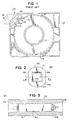
- Fig. 1 is a plan view of a conventional, single reel, magnetic tape cartridge, illustrating particularly the orientation of the leader block ;
- Fig. 2 is a top view of a preferred embodiment of the staking rod according to the present invention ;
- Fig. 3 is a side, cross-sectional view of the preferred embodiment of the staking rod of the present invention shown in Fig. 2 taken along lines 3-3 ;
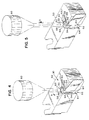
- Fig. 4 is a perspective view showing the preferred embodiment of the method according to the present invention, illustrating particularly insertion and turning of the staking rod via a tool ; and
- Fig. 5 is a perspective view showing the preferred embodiment of the method according to the present invention, illustrating particularly withdrawal of the tool once the staking rod is installed.
- The preferred embodiments of the present invention will now be described with reference to the drawings included herewith.
- As shown in Figs. 2 and 3, the
staking rod 30 according to the present invention is substantially cylindrical in shape. More particularly, thestaking rod 30 is preferably an elongated, injection moldedmember 31 having two opposed, substantially curved in cross-section, longitudinally extendingcylindrical sides longitudinal sides straight staking rod 30 also includes afirst end 42 and asecond end 44. Acoaxial opening 40 is formed preferably throughmember 31 from thefirst end 42 to thesecond end 44. In an alternate embodiment, the opening 40 is formed merely at thefirst end 42 and is not continuous through thestaking rod 30. The opening 40, is preferably square in cross-section but may have other cross-sectional polygonal shapes, such as a triangle or a rectangle. Because thestaking rod 30 is injection molded of e.g., acetal, manufacturing tolerances unavailable in the prior art are now made possible. - The method according to the present invention is illustrated by Figs. 4 and 5 and includes the following steps. First, a
leader block 50 is formed having a substantially cylindrical-shaped opening 52 formed therein. Thisopening 52 is accessible via its upper and/or lower end(s) and via alateral mouth 64. Then aleader tape 54 is positioned in the opening 52 through thelateral mouth 64 of theleader block 50. Further, thestaking rod 30 is formed as described above. - The opening 40 of the
staking rod 30 allows the use of atool 60 having a key ortip 62 corresponding in configuration to theopening 40 to manually or automatically enter, engage and transport thestaking rod 30 to theopening 64 formed in theleader block 50. Since thestaking rod 30 is narrower betweensides lateral mouth 64 of theopening 52 formed in theleader block 50, thestaking rod 30 can be moved laterally into theopening 52 in a direction perpendicular to the longitudinal axis of saidopening 52 formed in theleader block 50, as shown by arrow "A" in Fig. 4, such that thesides mouth 64. No interference fit is experienced at this time. Once inside theopening 52, thestaking rod 30 is rotated, e.g., clockwise, about the longitudinal axis of theopening 52 formed in theleader block 50, as indicated by arrow "B" in Fig. 4. That is, thetool 60 is used to rotate thestaking rod 30 to a point where its larger diameter, i.e., the . distance between the opposing cylindrically curvedsides curved walls leader tape 54 in position. Finally, thetool 60 is withdrawn from thestaking rod 30 in a direction colinearly with the longitudinal axis of theopening 52, as indicated by arrow "C" in Fig. 5 and is advanced to engage anotherstaking rod 30. - It can be seen that with the embodiments of the present invention, if, after inserting the staking rod 30 a molding imperfection is detected in either the tape cartridge components or the
staking rod 30, thestaking rod 30 may be removed easily via thesame tool 60 to allow for disassembly and correction of the imperfection. For example, if theleader block 50 is separated for replacement or repair, thestaking rod 30 can be retained for future use. - Overall, this invention provides a relatively simple design for a staking rod and related method of assembly which are particularly suited for automation since control of the staking rod during assembly is greatly enhanced. Thus, the present invention enjoys both the advantages of economical production and facilitated assembly and disassembly.
- The above described invention has been shown to be of the type intended for use in a single reel tape cartridge. However, the invention can be similarly applied to tape reels for use in audio or other recording and/or reproducing apparatus.
- The foregoing is considered illustrative only of the principles of the invention. Further, since numerous modifications and changes will readily occur to those skilled in the art, it is not desired to limit the invention to the exact construction and operation shown and described. Accordingly, all suitable modifications and equivalents may be resorted to, falling within the scope of the invention and the appended claims and their equivalents.
Claims (9)
Priority Applications (1)
| Application Number | Priority Date | Filing Date | Title |
|---|---|---|---|
| AT87400670T ATE66313T1 (en) | 1986-03-25 | 1987-03-25 | CONNECTION FROM BEGINNING OF TAPE FOR TAPE CASSETTE AND ITS MANUFACTURING PROCESS. |
Applications Claiming Priority (2)
| Application Number | Priority Date | Filing Date | Title |
|---|---|---|---|
| US06/843,688 US4694557A (en) | 1986-03-25 | 1986-03-25 | Leader tape staking rod and related method of assembly |
| US843688 | 1992-02-28 |
Publications (3)
| Publication Number | Publication Date |
|---|---|
| EP0239493A2 true EP0239493A2 (en) | 1987-09-30 |
| EP0239493A3 EP0239493A3 (en) | 1988-07-13 |
| EP0239493B1 EP0239493B1 (en) | 1991-08-14 |
Family
ID=25290734
Family Applications (1)
| Application Number | Title | Priority Date | Filing Date |
|---|---|---|---|
| EP87400670A Expired - Lifetime EP0239493B1 (en) | 1986-03-25 | 1987-03-25 | Leader tape block assembly for a tape cartridge and method for making the same |
Country Status (10)
| Country | Link |
|---|---|
| US (1) | US4694557A (en) |
| EP (1) | EP0239493B1 (en) |
| JP (1) | JPS62235084A (en) |
| KR (1) | KR900007041B1 (en) |
| AT (1) | ATE66313T1 (en) |
| CA (1) | CA1285068C (en) |
| DE (1) | DE3772077D1 (en) |
| ES (1) | ES2025174B3 (en) |
| GR (1) | GR3002952T3 (en) |
| MX (1) | MX164032B (en) |
Families Citing this family (5)
| Publication number | Priority date | Publication date | Assignee | Title |
|---|---|---|---|---|
| US5251090A (en) * | 1991-08-09 | 1993-10-05 | Storage Technology Corporation | Self sealing data storage element |
| US5261626A (en) * | 1992-02-10 | 1993-11-16 | Minnesota Mining And Manufacturing Company | Magnetic tape cartridge having self docking leader block |
| JP3707948B2 (en) * | 1999-02-17 | 2005-10-19 | 富士写真フイルム株式会社 | Magnetic tape cartridge |
| DE60037373T2 (en) * | 1999-09-08 | 2008-12-04 | Quantum Corp., San Jose | tape cartridge |
| WO2002039445A1 (en) * | 2000-11-13 | 2002-05-16 | Sony Corporation | Tape drive device, tape extraction device, and tape cassette |
Citations (3)
| Publication number | Priority date | Publication date | Assignee | Title |
|---|---|---|---|---|
| US3848265A (en) * | 1972-07-31 | 1974-11-12 | Information Terminals Corp | Tape cassette |
| US4213578A (en) * | 1978-02-24 | 1980-07-22 | Dai-Ichi Seiko Co., Ltd. | Cassette tape reel |
| US4283026A (en) * | 1978-08-14 | 1981-08-11 | U.S. Philips Corporation | Magnetic tape cassette |
Family Cites Families (7)
| Publication number | Priority date | Publication date | Assignee | Title |
|---|---|---|---|---|
| DE288020C (en) * | ||||
| US2397382A (en) * | 1944-06-19 | 1946-03-26 | Justice E Smith | Locking device |
| US3802638A (en) * | 1973-01-22 | 1974-04-09 | Addressograph Multigraph | Device for securing ribbons to spools |
| JPS5756388Y2 (en) * | 1978-08-11 | 1982-12-04 | ||
| US4383660A (en) * | 1981-03-30 | 1983-05-17 | International Business Machines Corp. | Single reel tape cartridge with leader block door seal |
| US4452406A (en) * | 1982-03-26 | 1984-06-05 | International Business Machines Corporation | Leader block for single reel tape cartridge |
| US4426047A (en) * | 1982-03-26 | 1984-01-17 | International Business Machines Corp. | Single reel tape cartridge |
-
1986
- 1986-03-25 US US06/843,688 patent/US4694557A/en not_active Expired - Fee Related
-
1987
- 1987-01-14 CA CA000527312A patent/CA1285068C/en not_active Expired - Fee Related
- 1987-01-22 KR KR1019870000514A patent/KR900007041B1/en not_active IP Right Cessation
- 1987-01-30 MX MX5107A patent/MX164032B/en unknown
- 1987-03-13 JP JP62058701A patent/JPS62235084A/en active Pending
- 1987-03-25 AT AT87400670T patent/ATE66313T1/en active
- 1987-03-25 ES ES87400670T patent/ES2025174B3/en not_active Expired - Lifetime
- 1987-03-25 EP EP87400670A patent/EP0239493B1/en not_active Expired - Lifetime
- 1987-03-25 DE DE8787400670T patent/DE3772077D1/en not_active Expired - Fee Related
-
1991
- 1991-10-22 GR GR91401583T patent/GR3002952T3/en unknown
Patent Citations (3)
| Publication number | Priority date | Publication date | Assignee | Title |
|---|---|---|---|---|
| US3848265A (en) * | 1972-07-31 | 1974-11-12 | Information Terminals Corp | Tape cassette |
| US4213578A (en) * | 1978-02-24 | 1980-07-22 | Dai-Ichi Seiko Co., Ltd. | Cassette tape reel |
| US4283026A (en) * | 1978-08-14 | 1981-08-11 | U.S. Philips Corporation | Magnetic tape cassette |
Non-Patent Citations (2)
| Title |
|---|
| IBM TECHNICAL DISCLOSURE BULLETIN, vol. 27, no. 1B, June 1984, page 812; L. CAMPBELL "Leader block attachment mechanism" * |
| IBM TECHNICAL DISCLOSURE BULLETIN, vol. 27, no. 5, October 1984, page 3185; M.E. RICHARD "Leader block tape attachment" * |
Also Published As
| Publication number | Publication date |
|---|---|
| KR870009372A (en) | 1987-10-26 |
| CA1285068C (en) | 1991-06-18 |
| US4694557A (en) | 1987-09-22 |
| JPS62235084A (en) | 1987-10-15 |
| DE3772077D1 (en) | 1991-09-19 |
| KR900007041B1 (en) | 1990-09-27 |
| ES2025174B3 (en) | 1992-03-16 |
| EP0239493B1 (en) | 1991-08-14 |
| MX164032B (en) | 1992-07-10 |
| EP0239493A3 (en) | 1988-07-13 |
| GR3002952T3 (en) | 1993-01-25 |
| ATE66313T1 (en) | 1991-08-15 |
Similar Documents
| Publication | Publication Date | Title |
|---|---|---|
| EP0239493B1 (en) | Leader tape block assembly for a tape cartridge and method for making the same | |
| EP0932155B1 (en) | Tape block and take-up reel assembly for a magnetic tape transport system | |
| EP1312571B1 (en) | Spool, especially for optical fiber media | |
| EP0071996A2 (en) | Magnetic recording tape cartridge | |
| US5687473A (en) | Apparatus and method for mounting a hairpin tube to a heat exchanger | |
| KR910001689Y1 (en) | Magnetic tape cassette | |
| EP0147513A1 (en) | Tape cassette dust door spring assembly and method for assembling same | |
| JPH05121143A (en) | Part conveyor | |
| US4736903A (en) | Self-locking hub assembly for a compact audio tape cassette and method for assembly | |
| US5211353A (en) | Spool with an integral bobbin holder | |
| DE60127359T2 (en) | Tape guide device and tape take-up reel for tape drive | |
| EP0575994A1 (en) | Method and apparatus for manufacturing spool of photographic film cassette | |
| WO1991008155A1 (en) | Disc container assembly | |
| US3796387A (en) | Hub-platform assembly for continuous-loop tapes | |
| KR0162120B1 (en) | Magnetic tape cartridge with second generation leader block and leader block pin | |
| DE102020100615B3 (en) | Component cassette, acceptance device and system with a component cassette and an acceptance device. | |
| EP0677769B1 (en) | Method and apparatus for assembling photographic film cassette | |
| JP2839403B2 (en) | Metal wire winding spool | |
| US5453895A (en) | Magnetic tape cassette with guide rib blades extending into a fixed hollow tape guide member | |
| US5573196A (en) | Cartridge and method for attaching or detaching a filmstrip to a film cartridge | |
| KR850002074Y1 (en) | Locking apparatus for cartridge | |
| US5495998A (en) | Tape reel structure for magnetic tape cassette | |
| KR0168583B1 (en) | Cassette with cathode and its carrying device for lithium battery | |
| US3697018A (en) | Reel and retaining means for motion picture film or the like | |
| JPS6134612Y2 (en) |
Legal Events
| Date | Code | Title | Description |
|---|---|---|---|
| PUAI | Public reference made under article 153(3) epc to a published international application that has entered the european phase |
Free format text: ORIGINAL CODE: 0009012 |
|
| AK | Designated contracting states |
Kind code of ref document: A2 Designated state(s): AT BE CH DE ES FR GB GR IT LI LU NL SE |
|
| PUAL | Search report despatched |
Free format text: ORIGINAL CODE: 0009013 |
|
| AK | Designated contracting states |
Kind code of ref document: A3 Designated state(s): AT BE CH DE ES FR GB GR IT LI LU NL SE |
|
| RHK1 | Main classification (correction) |
Ipc: G11B 15/67 |
|
| 17P | Request for examination filed |
Effective date: 19890111 |
|
| 17Q | First examination report despatched |
Effective date: 19900418 |
|
| GRAA | (expected) grant |
Free format text: ORIGINAL CODE: 0009210 |
|
| AK | Designated contracting states |
Kind code of ref document: B1 Designated state(s): AT BE CH DE ES FR GB GR IT LI LU NL SE |
|
| PG25 | Lapsed in a contracting state [announced via postgrant information from national office to epo] |
Ref country code: AT Effective date: 19910814 |
|
| REF | Corresponds to: |
Ref document number: 66313 Country of ref document: AT Date of ref document: 19910815 Kind code of ref document: T |
|
| REF | Corresponds to: |
Ref document number: 3772077 Country of ref document: DE Date of ref document: 19910919 |
|
| ITF | It: translation for a ep patent filed | ||
| ET | Fr: translation filed | ||
| REG | Reference to a national code |
Ref country code: ES Ref legal event code: FG2A Ref document number: 2025174 Country of ref document: ES Kind code of ref document: B3 |
|
| PGFP | Annual fee paid to national office [announced via postgrant information from national office to epo] |
Ref country code: SE Payment date: 19920317 Year of fee payment: 6 Ref country code: GB Payment date: 19920317 Year of fee payment: 6 |
|
| PGFP | Annual fee paid to national office [announced via postgrant information from national office to epo] |
Ref country code: ES Payment date: 19920325 Year of fee payment: 6 |
|
| PGFP | Annual fee paid to national office [announced via postgrant information from national office to epo] |
Ref country code: FR Payment date: 19920327 Year of fee payment: 6 |
|
| PGFP | Annual fee paid to national office [announced via postgrant information from national office to epo] |
Ref country code: GR Payment date: 19920330 Year of fee payment: 6 |
|
| PGFP | Annual fee paid to national office [announced via postgrant information from national office to epo] |
Ref country code: NL Payment date: 19920331 Year of fee payment: 6 |
|
| PGFP | Annual fee paid to national office [announced via postgrant information from national office to epo] |
Ref country code: CH Payment date: 19920409 Year of fee payment: 6 |
|
| PGFP | Annual fee paid to national office [announced via postgrant information from national office to epo] |
Ref country code: LU Payment date: 19920415 Year of fee payment: 6 |
|
| PGFP | Annual fee paid to national office [announced via postgrant information from national office to epo] |
Ref country code: DE Payment date: 19920421 Year of fee payment: 6 |
|
| PGFP | Annual fee paid to national office [announced via postgrant information from national office to epo] |
Ref country code: BE Payment date: 19920428 Year of fee payment: 6 |
|
| PLBE | No opposition filed within time limit |
Free format text: ORIGINAL CODE: 0009261 |
|
| STAA | Information on the status of an ep patent application or granted ep patent |
Free format text: STATUS: NO OPPOSITION FILED WITHIN TIME LIMIT |
|
| 26N | No opposition filed | ||
| REG | Reference to a national code |
Ref country code: GR Ref legal event code: FG4A Free format text: 3002952 |
|
| EPTA | Lu: last paid annual fee | ||
| PG25 | Lapsed in a contracting state [announced via postgrant information from national office to epo] |
Ref country code: LU Free format text: LAPSE BECAUSE OF NON-PAYMENT OF DUE FEES Effective date: 19930325 Ref country code: GB Effective date: 19930325 |
|
| PG25 | Lapsed in a contracting state [announced via postgrant information from national office to epo] |
Ref country code: SE Effective date: 19930326 Ref country code: ES Free format text: LAPSE BECAUSE OF NON-PAYMENT OF DUE FEES Effective date: 19930326 |
|
| PG25 | Lapsed in a contracting state [announced via postgrant information from national office to epo] |
Ref country code: LI Effective date: 19930331 Ref country code: CH Effective date: 19930331 Ref country code: BE Effective date: 19930331 |
|
| BERE | Be: lapsed |
Owner name: SHAPE INC. Effective date: 19930331 |
|
| PG25 | Lapsed in a contracting state [announced via postgrant information from national office to epo] |
Ref country code: GR Free format text: THE PATENT HAS BEEN ANNULLED BY A DECISION OF A NATIONAL AUTHORITY Effective date: 19930930 |
|
| PG25 | Lapsed in a contracting state [announced via postgrant information from national office to epo] |
Ref country code: NL Effective date: 19931001 |
|
| NLV4 | Nl: lapsed or anulled due to non-payment of the annual fee | ||
| GBPC | Gb: european patent ceased through non-payment of renewal fee |
Effective date: 19930325 |
|
| PG25 | Lapsed in a contracting state [announced via postgrant information from national office to epo] |
Ref country code: FR Effective date: 19931130 |
|
| REG | Reference to a national code |
Ref country code: CH Ref legal event code: PL |
|
| PG25 | Lapsed in a contracting state [announced via postgrant information from national office to epo] |
Ref country code: DE Effective date: 19931201 |
|
| REG | Reference to a national code |
Ref country code: FR Ref legal event code: ST |
|
| REG | Reference to a national code |
Ref country code: GR Ref legal event code: MM2A Free format text: 3002952 |
|
| EUG | Se: european patent has lapsed |
Ref document number: 87400670.3 Effective date: 19931008 |
|
| REG | Reference to a national code |
Ref country code: ES Ref legal event code: FD2A Effective date: 19990201 |
|
| PG25 | Lapsed in a contracting state [announced via postgrant information from national office to epo] |
Ref country code: IT Free format text: LAPSE BECAUSE OF NON-PAYMENT OF DUE FEES;WARNING: LAPSES OF ITALIAN PATENTS WITH EFFECTIVE DATE BEFORE 2007 MAY HAVE OCCURRED AT ANY TIME BEFORE 2007. THE CORRECT EFFECTIVE DATE MAY BE DIFFERENT FROM THE ONE RECORDED. Effective date: 20050325 |