EP0239459B1 - Thermometervorrichtung mit Umhüllung - Google Patents
Thermometervorrichtung mit Umhüllung Download PDFInfo
- Publication number
- EP0239459B1 EP0239459B1 EP87400516A EP87400516A EP0239459B1 EP 0239459 B1 EP0239459 B1 EP 0239459B1 EP 87400516 A EP87400516 A EP 87400516A EP 87400516 A EP87400516 A EP 87400516A EP 0239459 B1 EP0239459 B1 EP 0239459B1
- Authority
- EP
- European Patent Office
- Prior art keywords
- sheath
- sensor
- contact blades
- thermistor
- piston
- Prior art date
- Legal status (The legal status is an assumption and is not a legal conclusion. Google has not performed a legal analysis and makes no representation as to the accuracy of the status listed.)
- Expired - Lifetime
Links
- 239000000463 material Substances 0.000 claims abstract description 4
- 239000004020 conductor Substances 0.000 claims description 3
- 238000000465 moulding Methods 0.000 claims description 3
- 239000013013 elastic material Substances 0.000 claims description 2
- 239000004065 semiconductor Substances 0.000 description 10
- 238000005406 washing Methods 0.000 description 7
- 239000008188 pellet Substances 0.000 description 5
- 239000003570 air Substances 0.000 description 4
- 239000002184 metal Substances 0.000 description 4
- 238000010438 heat treatment Methods 0.000 description 3
- 238000004519 manufacturing process Methods 0.000 description 3
- 238000000034 method Methods 0.000 description 3
- XLYOFNOQVPJJNP-UHFFFAOYSA-N water Substances O XLYOFNOQVPJJNP-UHFFFAOYSA-N 0.000 description 3
- 230000006835 compression Effects 0.000 description 2
- 238000007906 compression Methods 0.000 description 2
- 238000001035 drying Methods 0.000 description 2
- 230000000694 effects Effects 0.000 description 2
- 238000007789 sealing Methods 0.000 description 2
- 239000002470 thermal conductor Substances 0.000 description 2
- OKTJSMMVPCPJKN-UHFFFAOYSA-N Carbon Chemical compound [C] OKTJSMMVPCPJKN-UHFFFAOYSA-N 0.000 description 1
- 239000004743 Polypropylene Substances 0.000 description 1
- XUIMIQQOPSSXEZ-UHFFFAOYSA-N Silicon Chemical compound [Si] XUIMIQQOPSSXEZ-UHFFFAOYSA-N 0.000 description 1
- 238000004026 adhesive bonding Methods 0.000 description 1
- 229910052799 carbon Inorganic materials 0.000 description 1
- 238000002485 combustion reaction Methods 0.000 description 1
- 238000010411 cooking Methods 0.000 description 1
- 238000001816 cooling Methods 0.000 description 1
- 239000012777 electrically insulating material Substances 0.000 description 1
- 239000012530 fluid Substances 0.000 description 1
- 230000014759 maintenance of location Effects 0.000 description 1
- 238000005259 measurement Methods 0.000 description 1
- -1 polypropylene Polymers 0.000 description 1
- 229920001155 polypropylene Polymers 0.000 description 1
- 229910052710 silicon Inorganic materials 0.000 description 1
- 239000010703 silicon Substances 0.000 description 1
- 238000003466 welding Methods 0.000 description 1
Images

Classifications
-
- G—PHYSICS
- G01—MEASURING; TESTING
- G01K—MEASURING TEMPERATURE; MEASURING QUANTITY OF HEAT; THERMALLY-SENSITIVE ELEMENTS NOT OTHERWISE PROVIDED FOR
- G01K7/00—Measuring temperature based on the use of electric or magnetic elements directly sensitive to heat ; Power supply therefor, e.g. using thermoelectric elements
- G01K7/16—Measuring temperature based on the use of electric or magnetic elements directly sensitive to heat ; Power supply therefor, e.g. using thermoelectric elements using resistive elements
- G01K7/22—Measuring temperature based on the use of electric or magnetic elements directly sensitive to heat ; Power supply therefor, e.g. using thermoelectric elements using resistive elements the element being a non-linear resistance, e.g. thermistor
Definitions
- the present invention relates to a sheathed temperature sensor.
- thermo measuring instruments or devices and in industrial or household appliances such as heating, cooking, washing machines, dishwashers, dryers where the temperature of a medium, a fluid, water or air must be controlled or measured, often temperature sensors are used.
- thermosensors There are many known and commercially available temperature sensors. Some such as bimetallic thermostats with fixed temperatures, adjustable bulb and capillary thermostats, are at reasonable prices, but only usable in apparatus or devices with electromechanical operating circuits. The others, for example sensors based on semiconductors, are suitable for their use in electronic circuit apparatus or devices. Often, silicon-based sensors are sold at affordable prices as bare parts, not protected by an envelope, sheath or hood and are therefore not directly usable in more or less corrosive or polluted environments, for example in the water of washing machine or dishwasher tanks or in the hot air of a drying circuit of a dryer or washer-dryer.
- This sensor comprises a tubular metal sheath closed at one end, a set of pellets based on semi -conductors maintained assembled according to a predetermined electrical connection, mounted in the bottom of the bore of this sheath, spaced from the side walls of the latter but in electrical contact with this bottom, an electrically insulating plug closing the open end of this sheath and provided with an axial terminal for electrical connection in an axial passage hole, and a helical metal spring axially mounted between this insulating plug and this set of semiconductor-based pads making an electrical connection between this set and this axial terminal of electrical connection and exerting a firm application of this assembly against the bottom of this sheath to strengthen their contact and create a electrical connection through this set of semiconductor-based pads between this axial electrical terminal and another electrical connection terminal constituted by this metallic sheath.
- This sensor based on semiconductor comprises, in a manner analogous to the previous sensor, a tubular metal sheath closed at one end , a semiconductor based pad assembly formed by an axial superposition of two electrical contact end pieces and a central pad and disposed in the bottom of the bore of this sheath in electrical contact with this bottom and isolated from the wall of this sheath by an electrically insulating sleeve, a contact piece provided with an annular seal and electrically insulating washers, closing the open end of this sheath and serving as a connection wire attachment terminal electric, and a helical metal spring axially mounted between this contact piece and this semiconductor-based pad assembly, isolated from the side walls d e this sheath by this insulating sleeve, making an electrical connection between this pellet assembly and this contact piece and exerting a firm application of this pellet assembly against the bottom of this sheath to strengthen their contact and create an electrical connection through this tablet set.
- Known temperature sensors described in documents EP-A-0 203 858 and DE-A-2 852 584 are intended to measure the temperature respectively for motor cars and trucks. These sensors are sensors based on semiconductors with complicated structures like those of the sensors mentioned in previous paragraphs. Their respective complicated structures are further weighed down by a bimetal warning system for exceeding a threshold temperature described in document EP-A-0 203 858 and by particular methods of mounting the semiconductor-based wafer on a or cooling plates.
- the aim of the present invention is to avoid these drawbacks and makes it possible to produce an effective temperature sensor suitable for electronic circuits, having a simple structure making it easy and economical to manufacture and assemble and provided with a sheath, envelope or hood. making it usable in corrosive or polluted environments such as the water in the tanks of washing machines or dishwashers or the hot air for drying a dryer or a washer-dryer.
- a temperature sensor provided with a tubular sheath closed at one end, open at the other end, containing in the closed bottom of its longitudinal bore a thermistor, is characterized in that it comprises in this tubular sheath on the one hand on the opposite lateral sides of the bore thereof, two contact blades making a electrical connection between this thermistor and the outside, and on the other hand a piston arranged in this bore of the sheath between these two contact blades, putting this thermistor in place in the bottom of the sheath and closing this sheath by its applied base and immobilized against the open end of this sheath, and in that the tubular sheath and the piston are made of a material which is a good thermal conductor and electrically insulating.
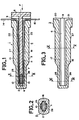
- a temperature sensor 1 comprises a thermistor 2 in the form of a pellet, metallized on its two opposite faces, a tubular sheath 3 closed at one of its ends, open at the other end and receiving in its bottom 4 the thermistor 2, a piston 5 sliding in the bore 6 of the tubular sheath 3, ensuring by pushing by the tip 7 of its body, a positioning of the thermistor 2 in the bottom 4 of the sheath tubular 3 and realizing by application and immobilization of its base 8 against the open end 9 of the tubular sheath 3, a closing of this sheath 3 and a holding in place of the thermistor 2, and two contact blades 10, 11 inserted longitudinally in the bore 6 between the sheath 3, the thermistor 2 and the piston 5, on the two diametrically opposite sides of the latter, effecting an electrical connection between this thermistor 2 and the outside, by elastic application e of their inner ends 12, 13 against the two opposite metallized faces of this thermistor,
- Thermistor 2 is constituted by that of a known type, for example that based on sintered carbon in the form of a pellet or disc with two opposite metallized faces.
- the tubular sheath 3 is made of a material of a known type such as polypropylene which is a good thermal conductor, electrically insulating and excellently resistant to the temperature of use of the sensor 1.
- the piston 5 is made of an electrically insulating material of a known type either identical to that of the sheath 3 or different from that of this sheath 3.
- the piston 5 comprises a rectangular body 19 and a circular or polygonal base 8.
- the tubular sheath 3 comprises a longitudinal bore 6 formed by a substantially rectangular central longitudinal hole 16 intended for the introduction and housing of the pellet-shaped thermistor 2 and for the sliding and housing of the body 19 with rectangular cross section of the piston 5, and two substantially rectangular longitudinal grooves 17,18 which laterally extend this central hole 16 to define a cross section of the bore 6, and are intended to receive the two contact blades 10 and 11.
- the tubular sheath 3 comprises in the face 9 at its open end, two radial recesses 20 and 21 which extend respectively the two lateral grooves 17, 18 of the bore 6 and respectively receive the outlet ends 14, 15 folded at right angles to the contact blades 10 and 11.
- the two contact blades 10 and 11 are made of an elastic material, a good electrical conductor.
- the contact blades 10 and 11 include internal ends 12 and 13 arched so as to obtain good contact between these blades 10 and 11 and the thermistor 2 under the effect of an elastic compression of these ends 12 and 13 against the sheath 3, by this thermistor 2.
- the contact blades 10 and 11 preferably include in their body spaced transverse camberings 22 and 23 forming longitudinal undulations which enhance their elasticity and ensure good retention of the piston 5 under the effect of an elastic compression of these contact blades 10 and 11 against the sheath 3 by the body 19 of this piston 5.
- the open end 9 of the sheath 3 is closed by the base 8 of the piston 5 is made according to a known fixing or sealing technique such as that by clips, by wedging, by gluing, by welding.
- the thickness of the sheath 3 is thinned in its zone surrounding the thermistor 2, by making two longitudinal and parallel flats 25, 26 in the closed end of this sheath 3.
- the sheath 3 comprises a flattened zone 25, 26 surrounding its closed end and a cylindrical zone 27, 9 or of polygonal section extending over its open end.
- the two contact blades 10, 11 are first placed in the rectangular lateral grooves 17, 18 of the sheath 3, the thermistor 2 is then introduced into the bottom of the bore 6 of the sheath 3 under the thrust of the piston 5 in the direction of the arrow F in FIG. 1 and the base 8 of this piston 5 is finally applied and fixed or sealed against the open end 9 of the sheath 3 to close it.
- the base of the piston 5 then occupies the position shown in broken lines in Figure 1 while the thermistor 2 abuts against the bottom 4 of the sheath, its position also being shown in broken lines.
- the improved structure of the sheathed temperature sensor 1 described above makes its manufacture and assembly easy, quick and therefore economical without compromising its efficiency.
- the two contact blades 10, 11 are incorporated into the sheath 3 by molding with the latter, and the mounting of the sensor 1 is reduced to an introduction of the thermistor 2 into the bottom 4 of the the bore of this sheath 3 using the piston 5 and a sealing or fixing of the base 8 of this piston 5 against the open end 9 of this sheath 3.
- the two contact blades 10, 11 are made integral with the piston 5 by a known technique such as that by clips, by molding ...
- the thermistor 2 is, during of a mounting of the sensor 1 is mounted between the elastic ends 12 and 13 of the contact blades 10, 11 integral with the piston 5 before the introduction of the latter into the bore 6 of the sheath 3 is introduced into the hole 16 of the bore 6 and placed in the bottom of the sheath 3 under the thrust of the piston 5 provided with contact blades 10, 11.
- the sheathed temperature sensor 1 is protected by the sheath 3 and the base 8 of the piston 5, against attack by corrosive or polluted environments in which a temperature control or measurement must be carried out.
- the economic temperature-sheathed sensor 1 can be part of a circuit of an apparatus or device for controlling or measuring temperature or of an industrial machine or of a household appliance such as a washing machine, a dishwasher, a dryer, a washer-dryer.
- the sheathed temperature sensor 1 can be either introduced through a hole not shown in the tank 31 and fixed in a sealed manner to this tank is mounted (FIG. 7) on a flange 33 of a heating element 34 and fixed at the same time as this heating element in the tank 31.
- the sheathed temperature sensor 1 is introduced through a hole in a hot air circulation pipe and fixed in place by known fixing means.
- the thermistor 2 of the sensor 1 protected by the sheath 3 good conductor of heat and electrically insulating, translates a variation of temperatures of this medium into a variation of electrical resistance of this thermistor and allows an electrical or electronic circuit of known type of an instrument or apparatus to transform this variation of electrical resistance into digital values of temperatures or into electrical control signals of another member or component of this electrical or electronic circuit.
- the thermistor 2 has a diameter of about 5.5 millimeters and a thickness of about 1.8 millimeters.
- the sheath 3 comprises on the one hand a body of the order of 35 millimeters in length and 9 millimeters in diameter, with a flattened zone at its closed end delimited by flats 25 and 26 parallel and spaced one from the another of the order of 7 millimeters and defining a sheath thickness of the order of 1.5 millimeters and with a bore formed by a rectangular hole of 5.6 millimeters by 2 millimeters, and two rectangular lateral grooves of 3 , 2 millimeters by 0.8 millimeters, and on the other hand at its open end, a circular edge of the order of 5 millimeters in length and 11 millimeters in diameter.
- the piston 5 comprises a rectangular body on the order of 5.3 millimeters in width, 32.4 millimeters in length and 1.8 millimeters in thickness and a circular base on the order of 11 millimeters in diameter and 2 millimeters thick.
- the contact blades 10 and 11 have a width of 2.8 millimeters and a thickness of about 0.6 millimeters.
- the sheathed temperature sensor 1 thus has a relatively small dimension, compact, in addition to the advantages of an economic cost price and excellent operating efficiency and reliability.
Landscapes
- Physics & Mathematics (AREA)
- Nonlinear Science (AREA)
- General Physics & Mathematics (AREA)
- Measuring Temperature Or Quantity Of Heat (AREA)
- Thermistors And Varistors (AREA)
- Superconductors And Manufacturing Methods Therefor (AREA)
- Vaporization, Distillation, Condensation, Sublimation, And Cold Traps (AREA)
- Sampling And Sample Adjustment (AREA)
- Cable Accessories (AREA)
- Glass Compositions (AREA)
Claims (9)
Priority Applications (1)
| Application Number | Priority Date | Filing Date | Title |
|---|---|---|---|
| AT87400516T ATE52854T1 (de) | 1986-03-14 | 1987-03-09 | Thermometervorrichtung mit umhuellung. |
Applications Claiming Priority (2)
| Application Number | Priority Date | Filing Date | Title |
|---|---|---|---|
| FR8603651A FR2595819B1 (fr) | 1986-03-14 | 1986-03-14 | Capteur gaine de temperature |
| FR8603651 | 1986-03-14 |
Publications (2)
| Publication Number | Publication Date |
|---|---|
| EP0239459A1 EP0239459A1 (de) | 1987-09-30 |
| EP0239459B1 true EP0239459B1 (de) | 1990-05-16 |
Family
ID=9333119
Family Applications (1)
| Application Number | Title | Priority Date | Filing Date |
|---|---|---|---|
| EP87400516A Expired - Lifetime EP0239459B1 (de) | 1986-03-14 | 1987-03-09 | Thermometervorrichtung mit Umhüllung |
Country Status (5)
| Country | Link |
|---|---|
| EP (1) | EP0239459B1 (de) |
| AT (1) | ATE52854T1 (de) |
| DE (1) | DE3762777D1 (de) |
| ES (1) | ES2015304B3 (de) |
| FR (1) | FR2595819B1 (de) |
Families Citing this family (3)
| Publication number | Priority date | Publication date | Assignee | Title |
|---|---|---|---|---|
| FR2645642B1 (fr) * | 1989-04-06 | 1994-01-21 | Jaeger | Capteur de temperature a thermistance et procede de fabrication de celui-ci |
| DE19549249C2 (de) * | 1995-12-19 | 1998-08-06 | Hartmann & Braun Gmbh & Co Kg | Gekapselter Temperaturfühler |
| DE19629963A1 (de) * | 1996-07-25 | 1998-01-29 | Mannesmann Vdo Ag | Sensor, insbesondere Temperatursensor, und Spritzgießwerkzeug zur Herstellung des Sensors |
Family Cites Families (4)
| Publication number | Priority date | Publication date | Assignee | Title |
|---|---|---|---|---|
| IT1100526B (it) * | 1977-12-05 | 1985-09-28 | Bendix Corp | Percettore della temperatura di un fluido |
| GB2140615B (en) * | 1983-03-22 | 1987-03-18 | Standard Telephones Cables Ltd | Thermistor composite |
| DE8400006U1 (de) * | 1984-01-02 | 1985-05-02 | Robert Bosch Gmbh, 7000 Stuttgart | Temperaturfühler |
| FR2582398B1 (fr) * | 1985-05-24 | 1987-08-21 | Jaeger | Dispositif de mesure de temperature avec contact d'alerte, en particulier pour vehicules automobiles |
-
1986
- 1986-03-14 FR FR8603651A patent/FR2595819B1/fr not_active Expired
-
1987
- 1987-03-09 AT AT87400516T patent/ATE52854T1/de not_active IP Right Cessation
- 1987-03-09 ES ES87400516T patent/ES2015304B3/es not_active Expired - Lifetime
- 1987-03-09 EP EP87400516A patent/EP0239459B1/de not_active Expired - Lifetime
- 1987-03-09 DE DE8787400516T patent/DE3762777D1/de not_active Expired - Fee Related
Also Published As
| Publication number | Publication date |
|---|---|
| FR2595819B1 (fr) | 1988-07-29 |
| FR2595819A1 (fr) | 1987-09-18 |
| EP0239459A1 (de) | 1987-09-30 |
| ATE52854T1 (de) | 1990-06-15 |
| DE3762777D1 (de) | 1990-06-21 |
| ES2015304B3 (es) | 1990-08-16 |
Similar Documents
| Publication | Publication Date | Title |
|---|---|---|
| FR2512202A1 (fr) | Sonde de temperature pour installations de chauffage ou de climatisation a air chaud | |
| EP2804516A1 (de) | Handtuchtrocknungsstrahler mit mindestens einer handtuchstange mit eingebautem kühlkörper mit einem elektrischen heizkabel | |
| FR2589236A3 (fr) | Dispositif de detection du niveau d'un liquide a l'interieur d'un conteneur | |
| FR2631117A1 (fr) | Dispositif perfectionne de mesure de temperature avec contact d'alerte | |
| FR2770077A1 (fr) | Chaudiere pour appareil electromenager et appareil electromenager comportant une telle chaudiere | |
| FR2595819A1 (fr) | Capteur gaine de temperature | |
| EP0082768A2 (de) | Temperaturdetektor und Vorrichtung zu dessen Anwendung | |
| FR2724727A1 (fr) | Capteur de temperature | |
| EP2350580B1 (de) | Einrichtung zur messung eines flüssigkeitsstands | |
| FR2660431A1 (fr) | Capteur de temperature a thermistance. | |
| WO1999038359A1 (fr) | Composant electrique comprenant une plaquette en ceramique portant une piste resistive et/ou conductrice serigraphiee | |
| WO2016185138A1 (fr) | Elément de renfort pour capteur hautes températures avec connecteur intégré | |
| EP3286535A1 (de) | Hochtemperatursensor mit integriertem verbinder | |
| FR2540374A1 (fr) | Dispositif de fixation pour sondes pyrometriques et barreaux de chauffage electrique | |
| FR2863705A1 (fr) | Capteur de mesure de la temperature d'un fluide. | |
| FR2645642A1 (fr) | Capteur de temperature a thermistance et procede de fabrication de celui-ci | |
| EP0575264B1 (de) | Wassererhitzer mit einem Lufttemperatursteuergerät | |
| EP0065441B1 (de) | Temperaturdetektoren | |
| EP1046730A1 (de) | Vorrichtung für den kathodischen Schutz eines Wassererhitzers, eines Warmwassererzeugers oder eines ähnlichen Behälters | |
| FR3045818A1 (fr) | Capteur hautes temperatures avec cavite pour materiau d'etancheite | |
| JPH1022066A (ja) | 流水の間接加熱装置 | |
| FR2645958A1 (fr) | Thermocouple etanche pour dispositif de securite electromagnetique notamment pour chaudieres ou chauffe-bains a gaz | |
| EP0419351A1 (de) | Elektrisches Rohrheizelement und seine Biegevorrichtung, und Austauscher mit einem solchen Element | |
| FR2894652A1 (fr) | "dispositif de regulation thermostatique de chauffe-eau electrique" | |
| FR2586401A1 (fr) | Recipient pour liquide, muni de thermostat monte etanche au travers de sa paroi |
Legal Events
| Date | Code | Title | Description |
|---|---|---|---|
| PUAI | Public reference made under article 153(3) epc to a published international application that has entered the european phase |
Free format text: ORIGINAL CODE: 0009012 |
|
| AK | Designated contracting states |
Kind code of ref document: A1 Designated state(s): AT DE ES FR IT |
|
| 17P | Request for examination filed |
Effective date: 19880115 |
|
| 17Q | First examination report despatched |
Effective date: 19890615 |
|
| GRAA | (expected) grant |
Free format text: ORIGINAL CODE: 0009210 |
|
| AK | Designated contracting states |
Kind code of ref document: B1 Designated state(s): AT DE ES FR IT |
|
| REF | Corresponds to: |
Ref document number: 52854 Country of ref document: AT Date of ref document: 19900615 Kind code of ref document: T |
|
| ITF | It: translation for a ep patent filed | ||
| REF | Corresponds to: |
Ref document number: 3762777 Country of ref document: DE Date of ref document: 19900621 |
|
| PGFP | Annual fee paid to national office [announced via postgrant information from national office to epo] |
Ref country code: DE Payment date: 19910225 Year of fee payment: 5 |
|
| PGFP | Annual fee paid to national office [announced via postgrant information from national office to epo] |
Ref country code: ES Payment date: 19910306 Year of fee payment: 5 |
|
| PG25 | Lapsed in a contracting state [announced via postgrant information from national office to epo] |
Ref country code: AT Effective date: 19910309 |
|
| PLBE | No opposition filed within time limit |
Free format text: ORIGINAL CODE: 0009261 |
|
| STAA | Information on the status of an ep patent application or granted ep patent |
Free format text: STATUS: NO OPPOSITION FILED WITHIN TIME LIMIT |
|
| ITTA | It: last paid annual fee | ||
| 26N | No opposition filed | ||
| PG25 | Lapsed in a contracting state [announced via postgrant information from national office to epo] |
Ref country code: ES Free format text: LAPSE BECAUSE OF NON-PAYMENT OF DUE FEES Effective date: 19920310 |
|
| PG25 | Lapsed in a contracting state [announced via postgrant information from national office to epo] |
Ref country code: DE Effective date: 19921201 |
|
| PGFP | Annual fee paid to national office [announced via postgrant information from national office to epo] |
Ref country code: FR Payment date: 19990323 Year of fee payment: 13 |
|
| REG | Reference to a national code |
Ref country code: ES Ref legal event code: FD2A Effective date: 19990301 |
|
| PG25 | Lapsed in a contracting state [announced via postgrant information from national office to epo] |
Ref country code: FR Free format text: LAPSE BECAUSE OF NON-PAYMENT OF DUE FEES Effective date: 20001130 |
|
| REG | Reference to a national code |
Ref country code: FR Ref legal event code: ST |
|
| PG25 | Lapsed in a contracting state [announced via postgrant information from national office to epo] |
Ref country code: IT Free format text: LAPSE BECAUSE OF NON-PAYMENT OF DUE FEES;WARNING: LAPSES OF ITALIAN PATENTS WITH EFFECTIVE DATE BEFORE 2007 MAY HAVE OCCURRED AT ANY TIME BEFORE 2007. THE CORRECT EFFECTIVE DATE MAY BE DIFFERENT FROM THE ONE RECORDED. Effective date: 20050309 |