EP0239397B1 - Amortisseurs et méthodes et appareil pour les tester sur place - Google Patents
Amortisseurs et méthodes et appareil pour les tester sur place Download PDFInfo
- Publication number
- EP0239397B1 EP0239397B1 EP19870302608 EP87302608A EP0239397B1 EP 0239397 B1 EP0239397 B1 EP 0239397B1 EP 19870302608 EP19870302608 EP 19870302608 EP 87302608 A EP87302608 A EP 87302608A EP 0239397 B1 EP0239397 B1 EP 0239397B1
- Authority
- EP
- European Patent Office
- Prior art keywords
- cylinder
- piston
- manifold
- control valves
- isolation
- Prior art date
- Legal status (The legal status is an assumption and is not a legal conclusion. Google has not performed a legal analysis and makes no representation as to the accuracy of the status listed.)
- Expired - Lifetime
Links
- 238000012360 testing method Methods 0.000 title claims abstract description 104
- 238000000034 method Methods 0.000 title claims abstract description 13
- 238000002955 isolation Methods 0.000 claims abstract description 20
- 239000012530 fluid Substances 0.000 claims description 55
- 238000004891 communication Methods 0.000 claims description 25
- 230000008878 coupling Effects 0.000 claims description 15
- 238000010168 coupling process Methods 0.000 claims description 15
- 238000005859 coupling reaction Methods 0.000 claims description 15
- 230000035939 shock Effects 0.000 claims description 3
- 230000000903 blocking effect Effects 0.000 claims 2
- 238000013461 design Methods 0.000 description 7
- 238000012986 modification Methods 0.000 description 7
- 230000004048 modification Effects 0.000 description 7
- 238000005202 decontamination Methods 0.000 description 4
- 230000003588 decontaminative effect Effects 0.000 description 4
- 238000007789 sealing Methods 0.000 description 4
- 238000010276 construction Methods 0.000 description 3
- 230000008602 contraction Effects 0.000 description 3
- 230000006866 deterioration Effects 0.000 description 3
- 238000010586 diagram Methods 0.000 description 3
- 230000000694 effects Effects 0.000 description 3
- 230000000737 periodic effect Effects 0.000 description 3
- 230000003213 activating effect Effects 0.000 description 2
- 230000008901 benefit Effects 0.000 description 2
- 238000006243 chemical reaction Methods 0.000 description 2
- 238000005516 engineering process Methods 0.000 description 2
- 238000007689 inspection Methods 0.000 description 2
- 238000009434 installation Methods 0.000 description 2
- 238000004519 manufacturing process Methods 0.000 description 2
- 230000005855 radiation Effects 0.000 description 2
- XLYOFNOQVPJJNP-UHFFFAOYSA-N water Substances O XLYOFNOQVPJJNP-UHFFFAOYSA-N 0.000 description 2
- 238000009835 boiling Methods 0.000 description 1
- 238000011109 contamination Methods 0.000 description 1
- 238000013270 controlled release Methods 0.000 description 1
- 230000001276 controlling effect Effects 0.000 description 1
- 239000002826 coolant Substances 0.000 description 1
- 238000005520 cutting process Methods 0.000 description 1
- 230000001419 dependent effect Effects 0.000 description 1
- 239000000463 material Substances 0.000 description 1
- 238000005259 measurement Methods 0.000 description 1
- 230000001105 regulatory effect Effects 0.000 description 1
- 230000008439 repair process Effects 0.000 description 1
- 238000003860 storage Methods 0.000 description 1
- 239000000126 substance Substances 0.000 description 1
Images


Classifications
-
- G—PHYSICS
- G01—MEASURING; TESTING
- G01M—TESTING STATIC OR DYNAMIC BALANCE OF MACHINES OR STRUCTURES; TESTING OF STRUCTURES OR APPARATUS, NOT OTHERWISE PROVIDED FOR
- G01M99/00—Subject matter not provided for in other groups of this subclass
Definitions
- This invention relates to the field of snubbers such as used in the nuclear power industry, and more particularly to methods and apparatus for in-place testing of such snubbers.
- Hydraulic snubbers are generally in the form of a hydraulic cylinder and piston assembly, with the cylinder being attached to a reaction wall or other support structure and the piston rod being attached to the equipment to be protected.
- the two chambers on the opposite sides of the piston are in communication with each other through control valves which remain open under normal conditions to allow the position of the piston within the cylinder to freely drift in accordance with the differential expansion encountered, but which valves effectively close or restrict under more dynamic conditions to relatively rigidly couple the equipment to the support structure. This rigid coupling eliminates devastating vibrations and resonances.
- Snubbers of this general type are manufactured by Paul-Munroe Hydraulics Inc., assignee of the present invention.
- Snubber sizes range from providing resistance loads of as little as several hundred kilograms (pounds) to in excess of one million kilograms (two million pounds).
- the corresponding weight of the larger units are in the one to (one and one-half ton) i.e. 1015 and 1500 kg range.
- the snubbers in Boiling Water Reactor plants (approximately 40 BWRs operating or under construction in the U. S.) generally do not exceed 68,000 kg (150,000 pounds) in capacity as opposed to the Pressurized Water Reactor plants (approximately 90 PWRs operating or under construction in the U. S.) utilizing up to the largest snubbers for protection of their reactor coolant pumps and steam generators.
- test bench tests the snubber directly by applying an external load to the snubber causing movement of the snubber piston which results in pressurization of the unit. This application of an external load tests the snubber in a manner analogous to its installed condition. While the test bench is a proven and reliable technology it requires the unit to be removed from the plant for testing. This is extremely expensive in terms of removal and reinstallation costs, outage costs, radiation exposure costs, snubber decontamination costs and testing costs. In some cases it is not possible to remove the snubbers without cutting out piping and concrete or removing equipment.
- test machines were developed in the last three years to allow testing of the snubbers in a partially installed condition. Although termed in-place testing, this in fact is a misnomer because removal of the rod end pin is required to perform the test.
- the in-place test is an indirect test of the snubber because the unit is pressurized by introducing snubber hydraulic fluid through fill and bleed plugs (26 and 27 in Figures 1 and 11) to initiate movement of the rod which simulates external loading.
- the snubber is tested for the same four tests as with the test bench: lockup and bleed test to verify the performance of the control valves, and breakaway and drag to verify the performance of the seals.
- lockup and bleed test to verify the performance of the control valves
- breakaway and drag to verify the performance of the seals.
- Current in-place testing techniques require performance of the breakaway and drag tests while the rod is being stroked, with the lockup and bleed tests being performed with the rod either fully extended or retracted.
- US - A - 4202209 discloses a system and method for in line testing of shock suppressor shut-off valves wherein a testing backpack with vacuum and fluid cannisters is connectable to port valves 156, 160 on conduit spurs of T-shaped ports of lines 154 and 158 between the chambers of a cylinder 122 of the shock suppressor device 120 and mutually opposing poppet valves 166 and 168 which are in communication with a reservoir 150 therebetween.
- the testing apparatus mutually communicates with valves 166, 168 and a respective chamber of the cylinder 122.
- the snubbers include a manifold between the hydraulic cylinder and each of the two control valves fastened thereto whereby for test purposes the control valves and hydraulic cylinder may be isolated from each other and coupled to a test machine for the independent testing thereof. Isolation of the control valves from the hydraulic cylinder allows separate testing of the control valves for lockup and bleed, and isolation of the hydraulic cylinder allows the testing of the cylinder for performance of the seals.
- Various embodiments are disclosed.
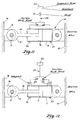
- Figure 1 is a side view of a Paul-Munroe prior art snubber.
- Figure 2 is a side view of a Paul-Munroe snubber in accordance with the present invention.
- Figure 3 is an expanded schematic side view of a manifold and test cartridge used in one embodiment of the present invention.
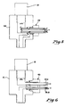
- Figure 4 is a side view of the manifold of Figure 3 with the test cartridge installed.
- FIGS 5 through 9 are side views of further modifications of the manifold and test cartridge to form embodiments of the present invention.
- Figure 10 is a diagram illustrating the testing configurations when utilizing the present invention.
- Figure 11 is a side view of a non-Paul-Munroe prior art snubber.
- Figure 12 is a side view of the non-Paul-Munroe snubber of Figure 11 when adapted to be in accordance with the present invention.
- FIG. 1 a diagram illustrating a typical prior art snubber installation may be seen.
- the snubber generally indicated by the numeral 10, is comprised of a hydraulic cylinder 11 having a piston 12 therein connected to a piston rod 13.
- the piston rod 13 in turn is coupled to the equipment 16 to be protected through a clevis arrangement comprising a clevis pin 17, coupling member 14 on the piston rod 13, and member 15 connected to the equipment to be protected.
- a similar clevis arrangement is also illustrated as coupling cylinder 11 to a fixed structure such as reaction wall 18.
- control valves 19 and 20 Located on cylinder 11 on opposite sides of the piston 12 are control valves 19 and 20 coupled to each other through line 23 and to a reservoir 22 of hydraulic fluid.
- the valve 21 is open and the cylinder 11 is filled with hydraulic fluid on both sides of piston 12.
- the reservoir of course assures an adequate supply of hydraulic fluid in spite of expansion and contraction thereof, etc., and of course provides temporary storage of the hydraulic fluid in the cylinder 11 displaced by the piston rod 13 as the piston 12 moves to the right, utilizing the relative orientations of Figure 1.
- control valves 19 and 20 are poppet valves which effectively provide nonlinear characteristics of the snubber.
- the poppet valves are open, allowing relatively free exchange of hydraulic fluid between the opposite sides of the piston and with the reservoir so that there is no substantial hydraulic resistance to the free movement of the piston as a result of such expansion and contraction.
- the poppet valve coupled to the cylinder chamber from which hydraulic fluid is flowing will close, now highly restricting the flow therefrom as determined by a relatively small bleed restriction in the valve.
- the tests of snubbers generally desired include lockup and bleed tests to verify the performance of the control valve, and breakaway and drag tests to verify the performance of the piston and piston rod seals.
- the lockup tests are intended to verify that the control valves will close at the desired piston speed, with the bleed test verifying the desired relatively low bleed rate through the control valves when closed.
- the breakaway and drag tests assure that the seals are in their proper place and have not deteriorated to the point of sticking, that the piston seal does not have excessive leakage and that there is no other seizure in the system, thereby assuring that the snubber is not unnecessarily loading the equipment to be protected during normal operation thereof which could result in instant or fatigue failures, and that the piston leakage will not effect proper operation of the snubber during extraordinary occurrences.
- FIG. 2 and Figure 12 a diagram similar to Figure 1 but illustrating the addition of the manifolds 24 and 25 in accordance with the present invention may be seen.
- each of the manifolds 24 and 25 is positioned between a respective one of control valves 19 and 20 and cylinder 11.
- snubber designs vary, a typical design will utilize control valves which are threaded into or tubed into the hydraulic cylinder as opposed to being integral therewith.
- specific design of the manifolds 24 and 25 will vary dependent upon the specific snubber design, such manifolds may be readily designed and installed in existing equipment without normally requiring any modification, or at least any substantial modification of the cylinder and/or control valves. Modification of a non-Paul Munroe Snubber may take the alternative form of redesigning the existing control valve block to directly incorporate the design features of the invention.
- the control valves merely screw into the wall of cylinder 11.
- the manifolds may be provided with corresponding male and female threaded regions so as to go into the cylinder in the place of the control valve and to receive the control valve thereon.
- Figure 3 wherein the body of a typical manifold, such as manifold 24, is provided with a female threaded region to receive control valve 19 and a corresponding male thread region 36' for threading into the cylinder 11 (see Figures 1 and 2).
- test cartridge 30 For this purpose a test cartridge, generally indicated by the numeral 30 (see Figures 3 and 4), is provided.
- the test cartridge includes a cartridge body 31 which may be threaded into manifold 24 in place of the seal plug 29, as illustrated in Figure 4.
- a central tube 32 Mounted to the body 31 is a central tube 32 having a seal 33 at the lower end thereof for sealing region 34 in communication with the hydraulic cylinder from region 35 in communication with the control valve 19 (or 20).
- seal 33 is only shown schematically, though it will be obvious to those experienced in hydraulics that various types of seals are readily available and suitable for the purpose as desired, whether for sealing on a face surface, a diameter or other suitable sealing surface.
- the test cartridge includes a pair of lines 36 and 37, line 36 being in fluid communication through the center of tube 32 so as to be in communication with the respective chamber of the cylinder, and line 37 being coupled to a port or opening between body 31 of the test cartridge and tube 32 supported thereby so as to be in fluid communication with chamber 35 and the control valve 19 (or 20) coupled thereto.
- the test cartridge in conjunction with the manifold is that the test cartridge essentially isolates the control valve from the cylinder, allowing fluid communication through the control valve separate and apart from the cylinder, and fluid communication with the cylinder separate and apart from the control valve. This allows various tests to be performed on both the snubber and the control valves as described below.
- test machine 54 which test machine includes a hydraulic reservoir, pumps, pressure gauges and flow controls to allow the measurement and control of various flow rates and pressures.
- test cartridge 30 is placed in each of manifolds 19 and 20 so that a total of four connections would be generally made to the test machine.
- lines 37 are used for controlling the flow of fluid from the test machine through one of lines 37.
- control valves 19 and 20 may be readily tested for, the other control valve normally being open for flow in that direction.
- the other control valve may be similarly tested.
- these tests may be conducted at any background pressure or pressures desired.
- the lines coupling the test machine to the manifolds may be of sufficient length so that the test machine itself and the operator or operators thereof need not enter the contaminated area except for very short periods of connection to the manifolds, thereby avoiding any decontamination expense for the test machine and minimizing the expenses associated with conducting work in contaminated regions.
- the piston seals are not self-actuating, in which case seal leakage may tend to increase with increased differential pressures across the piston of the snubber. Accordingly, such equipment may require periodic high pressure testing, in which case the "in place” testing of the snubber will require removal of the piston rod and to allow the movement of the piston to extreme positions whereat the required differential pressure may be imposed across the piston seal.
- these snubbers could be retrofitted with self activating seals which would allow them to realize the full benefits of true in-place testing.
- the manifolds 24 and 25 of Figure 2 may have any of various configurations, as can the test cartridge so long as the combination allows the temporary isolation of the control valves from the main snubber part.
- This is illustrated in various alternate modifications as shown in Figures 5 through 9.
- the manifold body 38 is similar to that shown in Figure 3, though the test cartridge, generally indicated by the numeral 39 connects through the side thereof rather than through the top of the manifold, as in the earlier described embodiment.
- test cartridge 40 also connects to the side of the manifold 41, though in a manner which effectively maintains the hydraulic lines 36a and 37a as separate lines or tubes within the manifold rather than utilizing a form of tube within a tube configuration as in the arrangements of Figures 3 through 5.
- valve 43 in Figure 7 a valve schematically illustrated as valve 43 in Figure 7 is incorporated as a permanent part of the manifold so that the valve may be used to controllably isolate and connect the respective cylinder volume and control valve.
- permanent connections are made to communicate with regions 44 and 45 by way of quick disconnect couplings 46 and 47 respectively.
- FIG. 8 illustrates a variation of that of Figure 7 wherein the valve, generally indicated by the numeral 48, cooperates with a valve seat in the body of the manifold, with a pair of quick disconnects 49 and 50 provided at the opposite side of the manifold for connection thereto.
- FIG 9 an arrangement similar to that of Figure 5 is shown.
- a test cartridge generally indicated by the numeral 51 is insertable through the side of the manifold 52, with seal 53 providing the seal between the two chambers in the manifold.
- a sliding seal member 54 provided with spring 56 is positioned to cause the seal 54 to follow the test cartridge as it is being removed (or installed) so that upon removal of the test cartridge, seal 54 will take a position to the right of opening 57 in the manifold so as to not affect communication between the cylinder and the control valve, but to prevent leakage through the port occupied by the test cartridge until the seal cap is attached thereto.
Landscapes
- Physics & Mathematics (AREA)
- General Physics & Mathematics (AREA)
- Fluid-Pressure Circuits (AREA)
- Radar Systems Or Details Thereof (AREA)
- Golf Clubs (AREA)
- Testing Resistance To Weather, Investigating Materials By Mechanical Methods (AREA)
- Testing Of Devices, Machine Parts, Or Other Structures Thereof (AREA)
- Electric Cable Installation (AREA)
- Analysing Materials By The Use Of Radiation (AREA)
- Investigating Or Analyzing Materials By The Use Of Ultrasonic Waves (AREA)
- Examining Or Testing Airtightness (AREA)
Claims (13)
- Dispositif pour coupler à, et protéger des chocs un objet mobile, ledit dispositif comprenant :- un cylindre (11) muni d'une première et d'une seconde extrémités, ledit cylindre contenant du fluide hydraulique,- un piston (12) disposé à l'intérieur dudit cylindre, ledit piston étant mobile entre lesdites première et seconde extrémités et ayant une tige de piston (13) couplée audit piston (12) et s'étendant à l'extérieur dudit cylindre,- un joint d'étanchéité couplé audit piston et disposé entre ledit piston et ledit cylindre, ledit joint empêchant l'écoulement du fluide hydraulique autour dudit piston,- un premier distributeur (24;38;41;52) ayant une première et une seconde ouvertures en communication de fluide l'une avec l'autre, la première ouverture étant couplée audit cylindre (11), de façon adjacente à ladite première extrémité pour être en communication de fluide avec celle-ci,- un second distributeur (25;38;41;52) ayant une première et une seconde ouvertures en communication de fluide l'une avec l'autre, la première ouverture étant couplée audit cylindre (11), de façon adjacente à ladite seconde extrémité pour être en communication de fluide avec celle-ci,- des vannes de commande (19,20), couplées à chacune desdites secondes ouvertures desdits premier et second distributeurs et l'une à l'autre, lesdites vannes de commande permettant la circulation du fluide hydraulique à l'extérieur par rapport audit cylindre, à partir de ladite première extrémité vers la seconde extrémité, et à partir de ladite seconde extrémité vers la première extrémité, en réponse au mouvement dudit piston (12), caractérisé par la caractéristique selon laquelle lesdits distributeurs (24,25,38,41,52) comportent chacun des moyens (33,43,48,53) pour isoler l'une de l'autre lesdites première et seconde ouvertures et pour les coupler à une machine de test pour une communication de fluide indépendante avec lesdites première et seconde ouvertures du distributeur respectif,de manière que ledit joint d'étanchéité puisse être testé de manière isolée desdites vannes de commande (19,20) et que lesdites vannes de commande puissent être testées isolément dudit joint d'étanchéité lorsque le dispositif est en place.
- Dispositif selon la revendication 1 dans lequel lesdits moyens pour isoler lesdites première et seconde ouvertures comprennent une cartouche de test (30,39,40,51) pour isoler ladite première ouverture de ladite seconde ouverture lorsqu'elle est montée sur ledit distributeur.
- Dispositif selon la revendication 2 dans lequel ladite cartouche (30,39,40,45) comporte une pluralité de systèmes de montage, l'un de ces systèmes de montage (36) assurant la communication avec une vanne de commande respective (19,20), l'autre desdits systèmes de montage assurant la communication avec l'extrémité respective dudit cylindre.
- Dispositif selon la revendication 1 dans lequel lesdits moyens pour isoler lesdites première et seconde ouvertures comprennent une vanne (47,48), faisant partie intégrante des distributeurs pour isoler ladite première ouverture et la seconde ouverture,
- Amortisseur comprenant :- un cylindre hydraulique (11) ayant un piston (12) y coulissant et rendu étanche vis-à-vis du cylindre par un joint de piston, ledit cylindre hydraulique (11) ayant une première et une seconde chambres de cylindre sur des côtés opposés dudit piston (12) remplies de fluide hydraulique,- des moyens de communication de fluide (23,24,25,38,41,52), couplés à ladite première et à ladite seconde chambres de cylindre pour assurer la communication hydraulique entre elles;- lesdits moyens de communication de fluide étant couplés aux dites chambres de cylindre par des vannes de commande (19,20), lesdites vannes de commande constituant un moyen pour commander la circulation du fluide hydraulique au travers desdites vannes, en réponse au mouvement dudit piston (12) dans ledit cylindre (11).caractérisé par :- des moyens d'isolation (33,43,48,53) dans lesdits moyens de communication de fluide pour bloquer, de façon contrôlable la communication du fluide entre lesdites première et seconde chambres et lesdites vannes de commande (19,20),- des premiers moyens de couplage (37) connectés aux dits moyens de communication de fluide (23, 24,25,38,41,52), de chaque côté desdites vannes de commande (19,20), lesdits moyens de couplage constituant un moyen de couplage sur une machine de test pour fournir, de façon contrôlable une circulation de fluide au travers desdites vannes (19,20) et non à l'une ou l'autre desdites première et seconde chambres de cylindre lorsqu'elle est bloquée par lesdits moyens d'isolation, et,- des seconds moyens de couplage (36) couplés aux dites première et seconde chambres de cylindre, lesdits seconds moyens de couplage (36) constituant un moyen de couplage sur une machine de test (54) pour fournir, de façon contrôlable, une circulation de fluide dans et vers l'extérieur desdites première et seconde chambres de cylindre et non au travers desdites vannes (19,20), lorsqu'elle est bloquée par lesdits moyens d'isolation (33,43,48,53), de manière que ledit joint d'étanchéité du piston puisse être testé en étant isolé desdites vannes (19,20) et que lesdites vannes de commande puissent être testées en étant isolées dudit joint du piston lorsque ledit amortisseur (10) est en place.
- Amortisseur hydraulique (10) comportant un piston (12) disposé dans un cylindre (11) contenant un fluide hydraulique, un joint d'étanchéité disposé entre ledit cylindre et ledit piston et des vannes de commande (19,20) couplées à une première et une seconde extrémités respectives dudit cylindre et l'une à l'autre, pour permettre la circulation dudit fluide d'une extrémité à l'autre lors du déplacement dudit piston (12), caractérisé par la caractéristique selon laquelle on prévoit un distributeur (24,25,38,41,52) disposé entre chacune des vannes de commande et ledit cylindre (11), des moyens d'isolation (33,43,48,53) pour empêcher, de façon contrôlable, la circulation dudit fluide hydraulique entre ledit cylindre (11) et lesdites vannes de commande (19,20) et des moyens (30,39,40,51) pour assurer le couplage sur chaque distributeur en communication indépendante de fluide avec ledit cylindre (11) et lesdites vannes de commande (19,20),
de manière que lesdites vannes de commande puissent être testées en étant isolées dudit joint et que ledit joint puisse être testé en étant isolé desdites vannes lorsque l'amortisseur (10) est en place. - Dispositif selon la revendication 6 dans lequel les distributeurs (24,25,38,41,52) comportent une première ouverture pour monter ladite vanne de commande de façon amovible, une seconde ouverture pour permettre l'accès du fluide hydraulique dans ledit cylindre (11) et une troisième ouverture pour monter lesdits moyens d'isolation (33,43,48,53) de façon amovible.
- Dispositif selon la revendication 7 selon lequel lesdits moyens d'isolation comprennent une cartouche de test (30,39,40,51) et ladite cartouche isole ladite première ouverture de ladite seconde ouverture lorsqu'elle est montée dans ledit distributeur (24,25,38,41,52).
- Dispositif selon la revendication 8 selon lequel ladite cartouche comporte une pluralité de systèmes de montage, l'un desdits montages permettant l'accès à ladite vanne de commande, l'autre l'accès audit cylindre.
- Dispositif selon la revendication 7 dans lequel les moyens d'isolation comprennent une vanne pour isoler ladite première ouverture de la seconde ouverture.
- Procédé pour tester in-situ un amortisseur hydraulique (10) comportant un cylindre (11) ayant une première et une seconde extrémités et contenant un fluide hydraulique, un piston mobile (12) disposé dans ledit cylindre, un joint d'étanchéité couplé audit piston (12) et disposé entre ledit piston et ledit cylindre, une tige (13) couplée audit piston (12) et à un objet protégé (16), des vannes de commande (19,20), couplées à la première et à la seconde extrémité respective dudit cylindre et l'une à l'autre et agissant en réponse à la circulation du fluide au travers d'elles, ledit procédé étant caractérisé par les étapes consistant à :a) prévoir un distributeur permanent (24,25,38,41,52) disposé entre chacune des vannes de commande (19,20) et ledit cylindre (11), ledit distributeur ayant une première ouverture pour y monter ladite vanne de commande, une seconde ouverture pour accéder audit cylindre (11) et permettant normalement la circulation du fluide entre elles, chaque distributeur comportant également une première connection pour une communication de fluide avec ladite première ouverture et une seconde connection pour une communication de fluide avec la seconde ouverture, la première et la seconde communications étant normalement bloquées à l'encontre de la circulation du fluide au travers d'elles;b) bloquer chacun des distributeurs pour empêcher le fluide de circuler entre la première ouverture et la seconde ouverture;c) débloquer lesdits première et seconde connections et coupler lesdites première et seconde connections de chaque distributeur à une machine de test (54) pour une alimentation contrôlable de fluide aux dites connections et à partir de celles-ci;d) tester lesdites vannes de commande (19,20) par une circulation contrôlée du fluide au travers de la première connection, en isolation de fluide dudit cylindre ete) tester ledit cylindre (11) par une circulation contrôlée du fluide au travers de ladite seconde connection, en isolation de fluide desdites vannes de commande.
- Procédé selon la revendication 11, dans lequel l'étape (b) est effectuée par des vannes qui comprennent un système faisant partie intégrante de chaque distributeur.
- Procédé selon la revendication 11 dans lequel les étapes b) et c) sont effectuées en introduisant une cartouche de test séparée (30,39,40,51) dans chaque distributeur.
Priority Applications (1)
| Application Number | Priority Date | Filing Date | Title |
|---|---|---|---|
| AT87302608T ATE89664T1 (de) | 1986-03-28 | 1987-03-26 | Stossdaempfer und verfahren und vorrichtung zur ueberpruefung an ort und stelle. |
Applications Claiming Priority (2)
| Application Number | Priority Date | Filing Date | Title |
|---|---|---|---|
| US845200 | 1986-03-28 | ||
| US06/845,200 US4702105A (en) | 1986-03-28 | 1986-03-28 | Snubbers and methods and apparatus for the in-place testing thereof |
Publications (3)
| Publication Number | Publication Date |
|---|---|
| EP0239397A2 EP0239397A2 (fr) | 1987-09-30 |
| EP0239397A3 EP0239397A3 (en) | 1990-05-23 |
| EP0239397B1 true EP0239397B1 (fr) | 1993-05-19 |
Family
ID=25294632
Family Applications (1)
| Application Number | Title | Priority Date | Filing Date |
|---|---|---|---|
| EP19870302608 Expired - Lifetime EP0239397B1 (fr) | 1986-03-28 | 1987-03-26 | Amortisseurs et méthodes et appareil pour les tester sur place |
Country Status (4)
| Country | Link |
|---|---|
| US (1) | US4702105A (fr) |
| EP (1) | EP0239397B1 (fr) |
| AT (1) | ATE89664T1 (fr) |
| DE (1) | DE3785877T2 (fr) |
Families Citing this family (7)
| Publication number | Priority date | Publication date | Assignee | Title |
|---|---|---|---|---|
| FR2673695B1 (fr) * | 1991-03-07 | 1995-01-27 | Framatome Sa | Procede et dispositif de controle d'un amortisseur hydraulique. |
| US7231820B2 (en) * | 2003-09-26 | 2007-06-19 | Dover Hydraulics, Inc. | Test stand for hydraulic oscillator using gas-filled shock absorbers |
| FR2868867B1 (fr) * | 2004-04-08 | 2006-07-21 | Framatome Anp Sas | Procede et installation de controle d'un dispositif de maintien d'un gros composant d'un reacteur nucleaire |
| DE202004008014U1 (de) * | 2004-05-18 | 2004-09-09 | Teko Automation, Mensch Und Technik Gmbh | Schwungphasensteuervorrichtung |
| DE102004054474B3 (de) * | 2004-11-11 | 2006-06-08 | Zf Friedrichshafen Ag | Schwingungsdämpfer mit verstellbarer Dämpfkraft |
| GB2442970B (en) * | 2006-07-11 | 2008-07-02 | Roper Ind Ltd | Packing case seal |
| US8065810B2 (en) * | 2009-04-07 | 2011-11-29 | Battelle Energy Alliance, Llc | Apparatus and systems for measuring elongation of objects, methods of measuring, and reactor |
Family Cites Families (15)
| Publication number | Priority date | Publication date | Assignee | Title |
|---|---|---|---|---|
| US2812954A (en) * | 1954-10-01 | 1957-11-12 | Karl J Kraus | Ride stabilizing system for automobiles |
| US3098382A (en) * | 1960-03-04 | 1963-07-23 | Lockheed Aircraft Corp | Hydraulic test equipment |
| US3795139A (en) * | 1971-12-23 | 1974-03-05 | Combustion Eng | Snubber seal leakage test circuit |
| US3771499A (en) * | 1971-12-30 | 1973-11-13 | Combustion Eng | Steam generator cradle support |
| FR2381943A1 (fr) * | 1977-02-23 | 1978-09-22 | Quiri & Cie Usines | Amortisseur autobloquant a compensation |
| US4131010A (en) * | 1977-11-09 | 1978-12-26 | E-Systems, Inc. | Hydraulic test set |
| DE2750737C2 (de) * | 1977-11-12 | 1985-06-05 | Brown Boveri Reaktor GmbH, 6800 Mannheim | Hydraulische Schwingungsbremse, insbesondere zum Einsatz in Kernkraftwerken |
| US4202209A (en) * | 1978-05-26 | 1980-05-13 | E-Systems, Inc. | Shock suppressor valve test system and method |
| US4192173A (en) * | 1978-07-26 | 1980-03-11 | Pacific Scientific Company | Eccentric pin mounting system |
| US4181017A (en) * | 1978-08-07 | 1980-01-01 | Markle Charles R | Fault detecting apparatus for fluid pressure systems |
| US4384591A (en) * | 1978-08-08 | 1983-05-24 | E-Systems, Inc. | Test in place valve and valve fitting |
| US4314473A (en) * | 1979-10-15 | 1982-02-09 | Anchor/Darling Industries, Inc. | Method and apparatus for testing snubbers in situ |
| US4423664A (en) * | 1981-04-10 | 1984-01-03 | Buchl Andrew F | Depth control apparatus |
| US4429563A (en) * | 1981-10-30 | 1984-02-07 | Anchor/Darling Industries, Inc. | Mechanical snubber apparatus |
| US4550589A (en) * | 1984-05-02 | 1985-11-05 | Pacific Scientific Company | System for monitoring snubber loads |
-
1986
- 1986-03-28 US US06/845,200 patent/US4702105A/en not_active Expired - Fee Related
-
1987
- 1987-03-26 EP EP19870302608 patent/EP0239397B1/fr not_active Expired - Lifetime
- 1987-03-26 DE DE87302608T patent/DE3785877T2/de not_active Expired - Fee Related
- 1987-03-26 AT AT87302608T patent/ATE89664T1/de not_active IP Right Cessation
Also Published As
| Publication number | Publication date |
|---|---|
| EP0239397A3 (en) | 1990-05-23 |
| ATE89664T1 (de) | 1993-06-15 |
| US4702105A (en) | 1987-10-27 |
| DE3785877T2 (de) | 1993-12-02 |
| EP0239397A2 (fr) | 1987-09-30 |
| DE3785877D1 (de) | 1993-06-24 |
Similar Documents
| Publication | Publication Date | Title |
|---|---|---|
| US3853702A (en) | Pressure vessel penetration technique | |
| US4694693A (en) | Check valve test method using truncated accumulator blowdown | |
| EP0239397B1 (fr) | Amortisseurs et méthodes et appareil pour les tester sur place | |
| US4770029A (en) | Valve testing method and device | |
| Dugone | SPERT III reactor facility: E-core revision | |
| EP0138477B1 (fr) | Ressort pour la fixation des éléments internes d'un réacteur | |
| US5375458A (en) | Leak test fixture | |
| US3795139A (en) | Snubber seal leakage test circuit | |
| US3844883A (en) | Pressure vessel penetration techniques | |
| US3855060A (en) | Bottom actuated reactor control rod devices | |
| CN217819169U (zh) | 一种压力仪表保护器 | |
| US4730706A (en) | Snubber with integral test structure | |
| EP0002126B1 (fr) | Frein hydraulique pour amortir le mouvement relatif de deux structures | |
| US5426680A (en) | Method for removing control rod drive using tool to verify control rod drive uncoupling | |
| US5426676A (en) | Extrusion-resistant seal assembly | |
| US4173511A (en) | Control rod blow out protection system | |
| US3844882A (en) | Lift piston assembly | |
| US3855059A (en) | Hydraulic system for nuclear reactors with hydraulically driven control rods | |
| US3843471A (en) | Top actuated reactor control system | |
| CN1029052C (zh) | 核反应堆容器中棒束导管上支座的楔牢装置 | |
| GB2175374A (en) | Check valve test method using truncated accumulator blowdown | |
| KR101449956B1 (ko) | 면진 장치, 면진 구조부의 교체 방법 및 면진 구조부의 하중 조절 방법 | |
| US11578805B2 (en) | Apparatus for conducting a hydraulic proof test | |
| US4126767A (en) | Bottom actuated reactor control system | |
| US5377241A (en) | Effluent container |
Legal Events
| Date | Code | Title | Description |
|---|---|---|---|
| PUAI | Public reference made under article 153(3) epc to a published international application that has entered the european phase |
Free format text: ORIGINAL CODE: 0009012 |
|
| AK | Designated contracting states |
Kind code of ref document: A2 Designated state(s): AT BE CH DE ES FR GB GR IT LI LU NL SE |
|
| RAP1 | Party data changed (applicant data changed or rights of an application transferred) |
Owner name: PAUL-MUNROE ENTERTECH |
|
| PUAL | Search report despatched |
Free format text: ORIGINAL CODE: 0009013 |
|
| AK | Designated contracting states |
Kind code of ref document: A3 Designated state(s): AT BE CH DE ES FR GB GR IT LI LU NL SE |
|
| 17P | Request for examination filed |
Effective date: 19900928 |
|
| 17Q | First examination report despatched |
Effective date: 19910729 |
|
| GRAA | (expected) grant |
Free format text: ORIGINAL CODE: 0009210 |
|
| AK | Designated contracting states |
Kind code of ref document: B1 Designated state(s): AT BE CH DE ES FR GB GR IT LI LU NL SE |
|
| PG25 | Lapsed in a contracting state [announced via postgrant information from national office to epo] |
Ref country code: IT Free format text: LAPSE BECAUSE OF FAILURE TO SUBMIT A TRANSLATION OF THE DESCRIPTION OR TO PAY THE FEE WITHIN THE PRE;WARNING: LAPSES OF ITALIAN PATENTS WITH EFFECTIVE DATE BEFORE 2007 MAY HAVE OCCURRED AT ANY TIME BEFORE 2007. THE CORRECT EFFECTIVE DATE MAY BE DIFFERENT FROM THE ONE RECORDED.SCRIBED TIME-LIMIT Effective date: 19930519 Ref country code: SE Effective date: 19930519 Ref country code: CH Effective date: 19930519 Ref country code: AT Effective date: 19930519 Ref country code: GR Free format text: LAPSE BECAUSE OF FAILURE TO SUBMIT A TRANSLATION OF THE DESCRIPTION OR TO PAY THE FEE WITHIN THE PRESCRIBED TIME-LIMIT Effective date: 19930519 Ref country code: LI Effective date: 19930519 Ref country code: NL Effective date: 19930519 Ref country code: BE Effective date: 19930519 |
|
| REF | Corresponds to: |
Ref document number: 89664 Country of ref document: AT Date of ref document: 19930615 Kind code of ref document: T |
|
| REF | Corresponds to: |
Ref document number: 3785877 Country of ref document: DE Date of ref document: 19930624 |
|
| ET | Fr: translation filed | ||
| PG25 | Lapsed in a contracting state [announced via postgrant information from national office to epo] |
Ref country code: ES Free format text: LAPSE BECAUSE OF FAILURE TO SUBMIT A TRANSLATION OF THE DESCRIPTION OR TO PAY THE FEE WITHIN THE PRESCRIBED TIME-LIMIT Effective date: 19930830 |
|
| REG | Reference to a national code |
Ref country code: CH Ref legal event code: PL |
|
| K2C1 | Correction of patent specification (title page) published |
Effective date: 19930519 |
|
| RAP4 | Party data changed (patent owner data changed or rights of a patent transferred) |
Owner name: PAUL-MUNROE ENERTECH |
|
| NLV1 | Nl: lapsed or annulled due to failure to fulfill the requirements of art. 29p and 29m of the patents act | ||
| PGFP | Annual fee paid to national office [announced via postgrant information from national office to epo] |
Ref country code: DE Payment date: 19940223 Year of fee payment: 8 |
|
| REG | Reference to a national code |
Ref country code: FR Ref legal event code: RM |
|
| PLBE | No opposition filed within time limit |
Free format text: ORIGINAL CODE: 0009261 |
|
| STAA | Information on the status of an ep patent application or granted ep patent |
Free format text: STATUS: NO OPPOSITION FILED WITHIN TIME LIMIT |
|
| PG25 | Lapsed in a contracting state [announced via postgrant information from national office to epo] |
Ref country code: LU Free format text: LAPSE BECAUSE OF NON-PAYMENT OF DUE FEES Effective date: 19940331 |
|
| 26N | No opposition filed | ||
| PGFP | Annual fee paid to national office [announced via postgrant information from national office to epo] |
Ref country code: GB Payment date: 19940926 Year of fee payment: 8 |
|
| PGFP | Annual fee paid to national office [announced via postgrant information from national office to epo] |
Ref country code: FR Payment date: 19950210 Year of fee payment: 9 |
|
| PG25 | Lapsed in a contracting state [announced via postgrant information from national office to epo] |
Ref country code: GB Effective date: 19950326 |
|
| GBPC | Gb: european patent ceased through non-payment of renewal fee |
Effective date: 19950326 |
|
| PG25 | Lapsed in a contracting state [announced via postgrant information from national office to epo] |
Ref country code: DE Effective date: 19951201 |
|
| PG25 | Lapsed in a contracting state [announced via postgrant information from national office to epo] |
Ref country code: FR Effective date: 19961129 |
|
| REG | Reference to a national code |
Ref country code: FR Ref legal event code: ST |