EP0238902A2 - Process and device for biological waste water purification - Google Patents
Process and device for biological waste water purification Download PDFInfo
- Publication number
- EP0238902A2 EP0238902A2 EP87103042A EP87103042A EP0238902A2 EP 0238902 A2 EP0238902 A2 EP 0238902A2 EP 87103042 A EP87103042 A EP 87103042A EP 87103042 A EP87103042 A EP 87103042A EP 0238902 A2 EP0238902 A2 EP 0238902A2
- Authority
- EP
- European Patent Office
- Prior art keywords
- carrier particles
- acceleration
- waste water
- biomass
- accelerated
- Prior art date
- Legal status (The legal status is an assumption and is not a legal conclusion. Google has not performed a legal analysis and makes no representation as to the accuracy of the status listed.)
- Granted
Links
Images
Classifications
-
- C—CHEMISTRY; METALLURGY
- C02—TREATMENT OF WATER, WASTE WATER, SEWAGE, OR SLUDGE
- C02F—TREATMENT OF WATER, WASTE WATER, SEWAGE, OR SLUDGE
- C02F3/00—Biological treatment of water, waste water, or sewage
- C02F3/02—Aerobic processes
- C02F3/08—Aerobic processes using moving contact bodies
- C02F3/085—Fluidized beds
-
- C—CHEMISTRY; METALLURGY
- C02—TREATMENT OF WATER, WASTE WATER, SEWAGE, OR SLUDGE
- C02F—TREATMENT OF WATER, WASTE WATER, SEWAGE, OR SLUDGE
- C02F3/00—Biological treatment of water, waste water, or sewage
- C02F3/02—Aerobic processes
- C02F3/10—Packings; Fillings; Grids
-
- Y—GENERAL TAGGING OF NEW TECHNOLOGICAL DEVELOPMENTS; GENERAL TAGGING OF CROSS-SECTIONAL TECHNOLOGIES SPANNING OVER SEVERAL SECTIONS OF THE IPC; TECHNICAL SUBJECTS COVERED BY FORMER USPC CROSS-REFERENCE ART COLLECTIONS [XRACs] AND DIGESTS
- Y02—TECHNOLOGIES OR APPLICATIONS FOR MITIGATION OR ADAPTATION AGAINST CLIMATE CHANGE
- Y02W—CLIMATE CHANGE MITIGATION TECHNOLOGIES RELATED TO WASTEWATER TREATMENT OR WASTE MANAGEMENT
- Y02W10/00—Technologies for wastewater treatment
- Y02W10/10—Biological treatment of water, waste water, or sewage
Definitions
- the invention relates to a process for the biological purification of waste water, in which the waste water is gassed with air and / or pure oxygen in a activated sludge tank in the presence of biomass fixed on carrier particles and then separated into purified water and activated sludge in a post-treatment, and a device for Execution of the procedure.
- the press regeneration is associated with a strong mechanical stress on the carrier particles.
- complex devices are necessary for this.
- the object of the present invention is therefore to design a method for the regeneration of carrier particles for biomass and an apparatus for carrying out the method in such a way that extensive regeneration of the carrier particles can be achieved in a simple and economical manner and the disadvantages of previous regeneration methods are eliminated.
- This object is achieved in that the carrier particles for regeneration in the activation tank are accelerated by means of a conveying medium and then braked.
- the carrier particles are first accelerated to an appropriate speed and then suddenly decelerated to zero. According to the kinetic energy released, a partial compression of the carrier particles is achieved. Depending on the selected achievable speed, the carrier particles can be compressed to about half their volume. The strong deceleration loosens the biomass in the carrier particle and partially flushes it out.
- the carrier particles are at a speed of 3 to 30 m / sec. accelerates, with a preferred speed range of 5 to 25 m / sec. extends.
- Pumps in particular mammoth pumps, can be used as the acceleration device, such as are used for returning the carrier particles from the drain screen of the activated sludge tank to the activated sludge tank.
- This has the advantage that the return device can also be used as a regeneration device by a simple measure, for example by attaching baffle plates.
- the regeneration method according to the invention therefore requires only little effort and is therefore also economically interesting. Due to the regeneration in the aeration tank, the degradation performance is increased and the sludge properties are improved. Because of the only partial compression of the carrier particles when braking, the method according to the invention only leads to a low material stress.
- the regeneration generally takes place during the entire operating time, the continuous loosening of the biomass in the carrier material and the resulting partial flushing out result in an effective regeneration.
- the carrier particles become lighter in the regeneration process due to the release of dead biomass, so that undesired deposits of carrier particles enriched with biomass at the start are avoided at the bottom of the activation tank.
- An expedient embodiment of the method according to the invention provides that the last quarter of the acceleration path of the carrier particles and the braking device are located outside the waste water in order to avoid impairment of the loosening and flushing out of the biomass caused by the partial compression by the surrounding water.
- a particularly advantageous embodiment for achieving high degrees of regeneration is that as much of the conveying medium (20 to 70%) as possible is separated off in the acceleration section, and thus the energy absorption takes place predominantly through the carrier particles.
- water can be used as the pumping medium. In denitrification plants, it is advisable to nitrate the carrier particles during the impact containing wastewater activated sludge mixture in order to accelerate denitrification processes.
- acceleration pipes installed, for example, operated with compressed air and advantageously with a short delivery length, can be used as the acceleration device, for example, in the vicinity of the reactor wall of the activation tank.
- Impact surfaces can be used as a braking device, which should expediently be made of polished stainless steel, but coating the surfaces with plastics such as polyethylene, polypropylene or Teflon is also advantageous for low material stress.
- the baffles can consist of straight or curved sheets. Baffle boxes without a bottom are particularly advantageous since this avoids splashing of the liquid.
- the biomass concentration in the carrier particles can be controlled by changing the exit velocity of the carrier particles from the acceleration path.
- the method can be used in all carrier-bound wastewater purification methods to intensify the purification process, the proportion of carrier particles in the total volume being between about 20 to 80 vol%.
- the carrier particles can have a diameter of 0.5 to 50 mm.
- Another possible application of inventing is the regeneration of loaded filter material during filtration with foam.
- the carrier particles or the filter material can be made of flexible polyurethane foam, urea / formaldehyde resins, polyethylene, polypropylene, silicone polymer or the like. consist.
- An apparatus for carrying out the method according to the invention comprises an activation tank which has an inlet for waste water to be cleaned and an outlet for purified waste water, carrier particles for the biomass being arranged in the activation tank, and acceleration and braking devices for the carrier particles being provided.
- the acceleration devices can be designed as pumps, the mammoth pumps being available for the return transport of the carrier particles.
- One possibility for realizing a device according to the invention is that a mammoth pump and an acceleration section are arranged such that the carrier particles are first accelerated in the water by the pump, but then the last quarter of the acceleration section is led out of the water and an impact surface is installed outside the water . After the impact of the carrier particles, they fall back into the reactor vessel.
- a further advantageous embodiment consists in that the acceleration devices are designed as acceleration tubes, which are expediently arranged in the vicinity of the reactor walls. These acceleration pipes can be equipped with a compressed air supply line.
- the impact surfaces can be designed as curved or straight sheets made of polished stainless steel or coated with plastic.
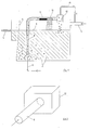
- 1 denotes a fully mixed activation tank for biological wastewater treatment.
- Carrier particles 2 e.g. Particles of flexible polyurethane foam, freely movable for the microorganisms.
- the total volume of the carrier material corresponds to a volume fraction of 25% of the volume of the activation tank 1.
- the wastewater to be treated is introduced into the activation tank 1 via an inlet 3, while the treated wastewater is drawn off via an outlet 4 arranged in the upper region of the activation tank 1, which is preceded by a separating device 5 for retaining the individual carrier particles, which, for example, consists of a simple one Sieve can exist.
- the carrier particles 2 in the vicinity of the pipe section 7 are pressed together with the surrounding waste water into the funnel-shaped pipe section 7 and accelerated together with the water in the subsequent pipe 8.
- the tube 8 protrudes from the water surface 9.
- a perforated plate 10 with an aperture 11 is attached in order to separate the carrier particles from the surrounding water.
- the water flows out of the tube through the holes, which have a diameter of 7 mm, while the carrier particles with a diameter of about 25 mm are retained in the tube.
- the perforated plate can be covered with the aperture 11 more or less, so that the proportion of the separated water is variable.
- part of the wastewater approximately 10 to 20% by volume, is branched off from the wastewater supply line 3 and led into the baffle box 12 via a flushing water line 13.
- Figure 2 shows schematically an impact box without a floor.
- the accelerating tube for the carrier particles is again designated by 8.
- Aeration tank volume 500 m3 (fully mixed)
- Carrier material concentration 25 vol .-% Pool depth: 4.5 m
- Pipe diameter 200 mm
- Air flow 300 m3 / h
- Conveying capacity 200 m3 / h
- Exit speed from the acceleration section 5 m / sec.
- Water separation approx. 70% (variable)
- Impact box dimensions 0.8 mx 0.3 x 0.6 m. (open at the bottom)
Landscapes
- Life Sciences & Earth Sciences (AREA)
- Biodiversity & Conservation Biology (AREA)
- Microbiology (AREA)
- Hydrology & Water Resources (AREA)
- Engineering & Computer Science (AREA)
- Environmental & Geological Engineering (AREA)
- Water Supply & Treatment (AREA)
- Chemical & Material Sciences (AREA)
- Organic Chemistry (AREA)
- Biological Treatment Of Waste Water (AREA)
- Separation Using Semi-Permeable Membranes (AREA)
Abstract
Die Erfindung betrifft ein Verfahren und eine Vorrichtung zur biologischen Reinigung von Abwasser, bei dem das Abwasser in einem Belebungsbecken in Gegenwart von auf Trägerteilchen (2) fixierter Biomasse mit Luft und/oder reinem Sauerstoff begast und anschließend in einer Nachklärung in gereinigtes Wasser und Belebtschlamm aufgetrennt wird. Da es im Kern der Trägerteilchen allmählich zum Absterben der Biomasse kommt, sind erfindungsgemäß Beschleunigungs-(6, 8) und Abbremseinrichtungen (12) vorgesehen, die eine Regenerierung der Trägerteilchen bewirken. Dabei werden die Trä gerteilchen beschleunigt und anschließend abgebremst, so daß gemäß der freiwerdenden kinetischen Energie ein partielles Zusammendrücken des Trägermaterials und dadurch eine Auflockerung und teilweise Ausschwemmung der abgestorbenen Biomasse erreicht wird. Durch Veränderung der Austrittsgeschwindigkeit aus der Beschleunigungsstrecke läßt sich die Biomassekonzentration im Trägerteilchen beeinflussen. 
Description
Die Erfindung betrifft ein Verfahren zur biologischen Reinigung von Abwasser, bei dem das Abwasser in einem Belebungsbecken in Gegenwart von auf Trägerteilchen fixierter Biomasse mit Luft und/oder reinem Sauerstoff begast und anschließend in einer Nachklärung in gereinigtes Wasser und Belebtschlamm aufgetrennt wird, sowie eine Vorrichtung zur Durchführung des Verfahrens.The invention relates to a process for the biological purification of waste water, in which the waste water is gassed with air and / or pure oxygen in a activated sludge tank in the presence of biomass fixed on carrier particles and then separated into purified water and activated sludge in a post-treatment, and a device for Execution of the procedure.
Bei trägergebundenen Reinigungsverfahren kommt es im Kern der Trägerteilchen allmählich zum Absterben der Biomasse, wodurch sich die Leistung der biologischen Abwasserreinigung verringert. Dieses Problem wird bisher dadurch gelöst, daß flexible Schaumstoffträger in einer externen Preßvorrichtung regeneriert werden. Dabei wird mineralisierte abgestorbene Biomasse aus Trägerteilchen entfernt und somit neue Ansiedlungsfläche geschaffen. Bei bekannten Verfahren nimmt beispielsweise ein Förderband die beladenen Trägerteilchen auf, führt sie einer Rollenpresse zu und wirft die nun leeren Trägerteilchen zurück in das Belebungsbecken.With carrier-based cleaning processes, the core of the carrier particles gradually leads to the death of the biomass, which reduces the performance of biological wastewater treatment. So far, this problem has been solved in that flexible foam carriers are regenerated in an external pressing device. Mineralized, dead biomass is removed from carrier particles and new settlement areas are created. In known methods, for example, a conveyor belt picks up the loaded carrier particles, feeds them to a roller press and throws the now empty carrier particles back into the activation tank.
Die Preßregenerierung ist jedoch mit einer starken mechanischen Beanspruchung der Trägerteilchen verbunden. Außerdem sind aufwendige Vorrichtungen dafür notwendig.The press regeneration is associated with a strong mechanical stress on the carrier particles. In addition, complex devices are necessary for this.
Aufgabe der vorliegenden Erfindung ist es daher, ein Verfahren zur Regenerierung von Trägerteilchen für Biomasse und eine Vorrichtung zur Durchführung des Verfahrens so auszugestalten, daß auf einfache und wirtschaftliche Weise eine weitgehende Regenerierung der Trägerteilchen erzielt werden kann und die Nachteile bisheriger Regenerierungsmethoden beseitigt werden.The object of the present invention is therefore to design a method for the regeneration of carrier particles for biomass and an apparatus for carrying out the method in such a way that extensive regeneration of the carrier particles can be achieved in a simple and economical manner and the disadvantages of previous regeneration methods are eliminated.
Diese Aufgabe wird erfindungsgemäß dadurch gelöst, daß die Trägerteilchen zur Regenerierung im Belebungsbecken mittels eines Fördermediums beschleunigt und anschließend abgebremst werden.This object is achieved in that the carrier particles for regeneration in the activation tank are accelerated by means of a conveying medium and then braked.
Die Trägerteilchen werden zuerst auf eine angemessene Geschwindigkeit beschleunigt und dann schlagartig auf Null abgebremst. Gemäß der freiwerdenden kinetischen Energie wird dabei ein partielles Zusammenpressen der Trägerteilchen erreicht. Entsprechend der gewählten erreichbaren Geschwindigkeit können die Trägerteilchen bis auf etwa die Hälfte ihres Volumens zusammengepreßt werden. Durch die starke Abbremsung wird die Biomasse im Trägerteilchen aufgelockert und zum Teil ausgeschwemmt. Vorteilhafterweise werden die Trägerteilchen dabei auf eine Geschwindigkeit von 3 bis 30 m/sec. beschleunigt, wobei sich ein bevorzugter Geschwindigkeitsbereich von 5 bis 25 m/sec. erstreckt.The carrier particles are first accelerated to an appropriate speed and then suddenly decelerated to zero. According to the kinetic energy released, a partial compression of the carrier particles is achieved. Depending on the selected achievable speed, the carrier particles can be compressed to about half their volume. The strong deceleration loosens the biomass in the carrier particle and partially flushes it out. Advantageously, the carrier particles are at a speed of 3 to 30 m / sec. accelerates, with a preferred speed range of 5 to 25 m / sec. extends.
Als Beschleunigungseinrichtung können Pumpen, insbesondere Mammutpumpen dienen, wie sie zur Rückförderung der Trägerteilchen vom Ablaufsieb des Belebungsbeckens in das Belebungsbecken verwendet werden. Dies hat den Vorteil, daß die Rückfördereinrichtung durch eine einfache Maßnahme, nämlich z.B. durch Anbringen von Prallblechen zusätzlich noch als Regeneriervorrichtung genützt werden kann. Die erfindungsgemäße Regenerierungsmethode erfordert also im Gegensatz zu bisher angewandten Verfahren nur einen geringen Aufwand und ist daher auch wirtschaftlich interessant. Durch die im Belebungsbecken erfolgende Regenerierung wird die Abbauleistung erhöht und werden die Schlammeigenschaften verbessert. Wegen des nur partiellen Zusammendrückens der Trägerteilchen beim Abbremsen führt die erfindungsgemäße Methode nur zu einer geringen Materialbeanspruchung. Da die Regenerierung in der Regel während der gesamten Betriebszeit stattfindet, wird durch die ständige Auflockerung der Biomasse im Trägermaterial und der damit verbundenen teilweisen Ausschwemmung eine wirksame Regenerierung erreicht. Gleichzeitig werden die Trägerteilchen bei dem Regenerierungsprozeß durch die Abgabe abgestorbener Biomasse leichter, so daß unerwünschte Ablagerungen von zu start mit Biomasse angereicherten Trägerteilchen am Boden des Belebungsbeckens vermieden werden.Pumps, in particular mammoth pumps, can be used as the acceleration device, such as are used for returning the carrier particles from the drain screen of the activated sludge tank to the activated sludge tank. This has the advantage that the return device can also be used as a regeneration device by a simple measure, for example by attaching baffle plates. In contrast to previously used methods, the regeneration method according to the invention therefore requires only little effort and is therefore also economically interesting. Due to the regeneration in the aeration tank, the degradation performance is increased and the sludge properties are improved. Because of the only partial compression of the carrier particles when braking, the method according to the invention only leads to a low material stress. Since the regeneration generally takes place during the entire operating time, the continuous loosening of the biomass in the carrier material and the resulting partial flushing out result in an effective regeneration. At the same time, the carrier particles become lighter in the regeneration process due to the release of dead biomass, so that undesired deposits of carrier particles enriched with biomass at the start are avoided at the bottom of the activation tank.
Eine zweckmäßige Ausgestaltung des erfindungsgemäßen Verfahrens sieht vor, daß sich etwa das letzte Viertel der Beschleunigungsstrecke der Trägerteilchen und die Abbremseinrichtung außerhalb des Abwassers befindet, um eine Beeinträchtigung der durch partielles Zusammendrücken bewirkten Auflockerung und Ausschwemmung der Biomasse durch das umgebende Wasser zu vermeiden. Eine besonders vorteilhafte Ausführung zur Erzielung hoher Regeneriergrade besteht darin, daß möglichst viel Fördermedium (20 bis 70%) in der Beschleunigungsstrecke abgetrennt wird, und somit die Energieabsorption vorwiegend durch die Trägerteilchen erfolgt. Als Fördermedium kommt beispielsweise Wasser in Betracht. Bei Denitrifikationsanlagen ist es zweckmäßig, die Trägerteilchen während des Aufpralls mit dem nitrat haltigen Abwasserbelebtschlammgemisch in Kontakt zu bringen, um Denitrifikationsvorgänge zu beschleunigen.An expedient embodiment of the method according to the invention provides that the last quarter of the acceleration path of the carrier particles and the braking device are located outside the waste water in order to avoid impairment of the loosening and flushing out of the biomass caused by the partial compression by the surrounding water. A particularly advantageous embodiment for achieving high degrees of regeneration is that as much of the conveying medium (20 to 70%) as possible is separated off in the acceleration section, and thus the energy absorption takes place predominantly through the carrier particles. For example, water can be used as the pumping medium. In denitrification plants, it is advisable to nitrate the carrier particles during the impact containing wastewater activated sludge mixture in order to accelerate denitrification processes.
Neben Mammutpumpen, wie sie zur Rückförderung der Trägerteilchen eingesetzt werden, können als Beschleunigungsvorrichtung auch beispielsweise in Nähe der Reaktorwand des Belebungsbeckens installierte, etwa mit Druckluft betriebene Beschleunigungsrohre mit vorteilhafterweise geringer Förderlänge verwendet werden. Als Abbremseinrichtung können einfach Aufprallflächen eingesetzt werden, die zweckmäßigerweise aus poliertem Edelstahl gefertigt werden sollten, aber auch eine Beschichtung der Flächen mit Kunststoffen wie Polyäthylen, Polypropylen oder Teflon ist vorteilhaft für eine geringe Materialbeanspruchung. Die Prallflächen können aus geraden oder gekrümmten Blechen bestehen. Besonders vorteilhaft sind Prallkästen ohne Boden, da dadurch ein Verspritzen der Flüssigkeit vermieden wird.In addition to mammoth pumps, such as those used for returning the carrier particles, acceleration pipes installed, for example, operated with compressed air and advantageously with a short delivery length, can be used as the acceleration device, for example, in the vicinity of the reactor wall of the activation tank. Impact surfaces can be used as a braking device, which should expediently be made of polished stainless steel, but coating the surfaces with plastics such as polyethylene, polypropylene or Teflon is also advantageous for low material stress. The baffles can consist of straight or curved sheets. Baffle boxes without a bottom are particularly advantageous since this avoids splashing of the liquid.
Mit dem Verfahren kann durch Veränderung der Austrittsgeschwindigkeit der Trägerteilchen aus der Beschleunigungsstrecke die Biomassekonzentration in den Trägerteilchen gesteuert werden.With the method, the biomass concentration in the carrier particles can be controlled by changing the exit velocity of the carrier particles from the acceleration path.
Das Verfahren kann in allen trägergebundenen Abwasserreinigungsverfahren zur Intensivierung des Reinigungsprozesses eingesetzt werden, wobei der Anteil der Tragerteilchen am Gesamtvolumen zwischen etwa 20 bis 80 Vol% liegen kann. Die Trägerteilchen können einen Durchmesser von 0,5 bis 50 mm besitzen. Als weitere Anwendungsmöglichkeit der Erfunding ist die Regenerierung von beladenem Filtermaterial bei Filtration mit Schaumstoff zu nennen. Die Trägerteilchen bzw. das Filtermaterial können dabei aus Polyurethanweichschaum, Harnstoff/Formaldehydharzen, Polyäthylen, Polypropylen, Silikonpolymer o.ä. bestehen. Eine Vorrichtung zur Durchführung des erfindungsgemäßen Verfahrens umfaßt ein Belebungsbecken, das einen Zulauf für zu reinigendes Abwasser und einen Ablauf für gereinigtes Abwasser aufweist, wobei in dem Belebungsbecken Trägerteilchen für die Biomasse angeordnet sind, und Beschleunigungs- und Abbremseinrichtungen für die Trägerteilchen vorgesehen sind. Die Beschleunigungseinrichtungen können als Pumpen ausgebildet sein, wobei sich die Mammutpumpen zur Rückförderung der Trägerteilchen anbieten. Eine Realisierungsmöglichkeit einer erfindungsgemäßen Vorrichtung besteht darin, daß eine Mammutpumpe und eine Beschleunigungsstrecke so angeordnet sind, daß die Trägerteilchen zunächst von der Pumpe im Wasser beschleunigt werden, dann aber das letzte Viertel der Beschleunigungsstrecke aus dem Wasser geführt wird und außerhalb des Wassers eine Aufprallfläche installiert wird. Nach dem Aufprall der Trägerteilchen fallen diese wieder zurück in den Reaktorbehälter.The method can be used in all carrier-bound wastewater purification methods to intensify the purification process, the proportion of carrier particles in the total volume being between about 20 to 80 vol%. The carrier particles can have a diameter of 0.5 to 50 mm. Another possible application of inventing is the regeneration of loaded filter material during filtration with foam. The carrier particles or the filter material can be made of flexible polyurethane foam, urea / formaldehyde resins, polyethylene, polypropylene, silicone polymer or the like. consist. An apparatus for carrying out the method according to the invention comprises an activation tank which has an inlet for waste water to be cleaned and an outlet for purified waste water, carrier particles for the biomass being arranged in the activation tank, and acceleration and braking devices for the carrier particles being provided. The acceleration devices can be designed as pumps, the mammoth pumps being available for the return transport of the carrier particles. One possibility for realizing a device according to the invention is that a mammoth pump and an acceleration section are arranged such that the carrier particles are first accelerated in the water by the pump, but then the last quarter of the acceleration section is led out of the water and an impact surface is installed outside the water . After the impact of the carrier particles, they fall back into the reactor vessel.
Eine weitere vorteilhafte Ausführungsform besteht darin, daß die Beschleunigungseinrichtungen als Beschleunigungsrohre ausgebildet sind, die zweckmäßigerweise in der Nähe der Reaktorwände angeordnet sind. Diese Beschleunigungsrohre können mit einer Druckluftzuleitung ausgestattet sein. Bei den beschriebenen Anordnungen können die Aufprallflächen als gekrümmte oder gerade Bleche aus poliertem Edelstahl oder mit Kunststoff beschichtet ausgebildet sein.A further advantageous embodiment consists in that the acceleration devices are designed as acceleration tubes, which are expediently arranged in the vicinity of the reactor walls. These acceleration pipes can be equipped with a compressed air supply line. In the arrangements described, the impact surfaces can be designed as curved or straight sheets made of polished stainless steel or coated with plastic.
Nachfolgend ist ein in zwei Figuren schematisch dargestelltes Ausführungsbeispiel näher beschrieben.An exemplary embodiment shown schematically in two figures is described in more detail below.
Es zeigen:
- Figur 1 Belebungsbecken mit Regeneriereinrichtung;
Figur 2 Prallkasten als Abbremseinrichtung.
- Figure 1 aeration tank with regeneration device;
- Figure 2 impact box as a braking device.
In Figur 1 ist mit 1 ein volldurchmischtes Belebungsbecken zur biologischen Abwasserreinigung bezeichnet. In dem Belebungsbecken 1 sind Trägerteilchen 2, z.B. Stoffteilchen aus Polyurethanweichschaum, für die Mikroorganismen frei beweglich angeordnet. Das Gesamtvolumen des Trägermaterials entspricht einem Volumenanteil von 25% des Volumens des Belebungsbeckens 1.In Figure 1, 1 denotes a fully mixed activation tank for biological wastewater treatment.
Das zu behandelnde Abwasser wird über einen Zulauf 3 in das Belebungsbecken 1 eingeleitet, während das behandelte Abwasser über einen im oberen Bereich des Belebungsbeckens 1 angeordneten Ablauf 4 abgezogen wird, dem eine Trenneinrichtung 5 zum Zurückhalten der einzelnen Trägerteilchen vorgeschaltet ist, die beispielsweise aus einem einfachen Sieb bestehen kann.The wastewater to be treated is introduced into the activation tank 1 via an inlet 3, while the treated wastewater is drawn off via an
In das Belebungsbecken 1 ist eine Druckluftzuleitung 6 eingeführt, die an einem trichterförmigen Rohrabschnitt 7 endet. Durch Druckluftzufuhr werden die Trägerteilchen 2 in Nähe des Rohrabschnittes 7 gemeinsam mit dem umgebenden Abwasser in den trichterförmigen Rohrabschnitt 7 gedrückt und zusammen mit dem Wasser im anschließenden Rohr 8 beschleunigt. Das Rohr 8 ragt aus der Wasseroberfläche 9 heraus. Im letzten Viertel der Rohrstrecke ist ein Lochblech 10 mit einer Blende 11 angebracht, um die Trägerteilchen vom umgebenden Wasser zu trennen. Das Wasser fließt durch die Löcher, die einen Durchmesser von 7 mm aufweisen, aus dem Rohr ab, während die Trägerteilchen mit etwa 25 mm Durchmesser im Rohr zurückgehalten werden. Das Lochblech kann mit der Blende 11 mehr oder weniger weit zugedeckt werden, so daß der Anteil des abgetrennten Wassers variierbar ist. Die Trägerteilchen gelangen in einen Prallkasten 12, der nach unten offen ist, prallen auf die Wände des Prallkastens 12 auf, werden dadurch schlagartig abgebremst und fallen, derart regeneriert, in das Belebungsbecken zurück. Um mögliche Rückstände von ausgeschwemmter Biomasse an den Prallkastenwänden abspülen zu können, wird ein Teil des Abwassers, etwa 10 bis 20 Vol%, von der Abwasserzuleitung 3 abgezweigt und über eine Spülwasserleitung 13 in den Prallkasten 12 geführt.A compressed
Figur 2 zeigt schematisch einen Prallkasten ohne Boden. Mit 8 wird wieder das Beschleunigungsrohr für die Trägerteilchen bezeichnet.Figure 2 shows schematically an impact box without a floor. The accelerating tube for the carrier particles is again designated by 8.
Nachstehend sind Zahlenangaben für ein Auslegungsbeispiel einer nach dem erfindungsgemäßen Verfahren betriebenen Belebungsanlage aufgeführt.The figures below give a design example of an activation system operated according to the method according to the invention.
Belebungsbeckenvolumen: 500 m³ (volldurchmischt)
Trägermaterialkonzentration: 25 Vol.-%
Beckentiefe: 4,5 m
Rohrdurchmesser: 200 mm
Luftdurchsatz: 300 m³/h
Förderleistung: 200 m³/h
Austrittsgeschwindigkeit aus der Beschleunigungsstrecke: 5 m/sec.
Wasserabtrennung: ca. 70% (variierbar)
Prallkastenabmessungen: 0,8 m x 0,3 x 0,6 m.
(nach unten offen)Aeration tank volume: 500 m³ (fully mixed)
Carrier material concentration: 25 vol .-%
Pool depth: 4.5 m
Pipe diameter: 200 mm
Air flow: 300 m³ / h
Conveying capacity: 200 m³ / h
Exit speed from the acceleration section: 5 m / sec.
Water separation: approx. 70% (variable)
Impact box dimensions: 0.8 mx 0.3 x 0.6 m.
(open at the bottom)
Claims (12)
Priority Applications (1)
| Application Number | Priority Date | Filing Date | Title |
|---|---|---|---|
| AT87103042T ATE65481T1 (en) | 1986-03-24 | 1987-03-04 | METHOD AND DEVICE FOR BIOLOGICAL PURIFICATION OF SEWAGE. |
Applications Claiming Priority (2)
| Application Number | Priority Date | Filing Date | Title |
|---|---|---|---|
| DE19863609898 DE3609898A1 (en) | 1986-03-24 | 1986-03-24 | METHOD AND DEVICE FOR BIOLOGICAL WASTE WATER TREATMENT |
| DE3609898 | 1986-03-24 |
Publications (3)
| Publication Number | Publication Date |
|---|---|
| EP0238902A2 true EP0238902A2 (en) | 1987-09-30 |
| EP0238902A3 EP0238902A3 (en) | 1988-10-19 |
| EP0238902B1 EP0238902B1 (en) | 1991-07-24 |
Family
ID=6297149
Family Applications (1)
| Application Number | Title | Priority Date | Filing Date |
|---|---|---|---|
| EP19870103042 Expired - Lifetime EP0238902B1 (en) | 1986-03-24 | 1987-03-04 | Process and device for biological waste water purification |
Country Status (3)
| Country | Link |
|---|---|
| EP (1) | EP0238902B1 (en) |
| AT (1) | ATE65481T1 (en) |
| DE (2) | DE3609898A1 (en) |
Cited By (5)
| Publication number | Priority date | Publication date | Assignee | Title |
|---|---|---|---|---|
| GB2250021A (en) * | 1990-11-14 | 1992-05-27 | Malcolm Goodson | Water treatment |
| EP0519258A1 (en) * | 1991-06-15 | 1992-12-23 | Lutz Dr. Haldenwang | Method and device for the continuous separation, purification and return of granular, floatable base material from reactors for biological water treatment |
| WO1995023767A1 (en) * | 1994-03-03 | 1995-09-08 | Nordic Water Products Ab | Processing water in a biologically activated and continuously operating granular filter bed |
| WO1996003351A1 (en) * | 1994-07-21 | 1996-02-08 | Knud Peter Brockdorff | A reactor for use in water treatment and micro film carriers for use in connection with said treatment as well as a method for operating the reactor |
| DE202019100864U1 (en) | 2019-02-15 | 2019-02-22 | AD Solutions UG (haftungsbeschränkt) | Dispersionshomogenisierer |
Family Cites Families (1)
| Publication number | Priority date | Publication date | Assignee | Title |
|---|---|---|---|---|
| DE3228365A1 (en) * | 1982-07-29 | 1984-02-02 | Linde Ag, 6200 Wiesbaden | METHOD AND DEVICE FOR BIOLOGICAL WASTE WATER TREATMENT |
-
1986
- 1986-03-24 DE DE19863609898 patent/DE3609898A1/en not_active Withdrawn
-
1987
- 1987-03-04 DE DE8787103042T patent/DE3771536D1/en not_active Expired - Fee Related
- 1987-03-04 AT AT87103042T patent/ATE65481T1/en active
- 1987-03-04 EP EP19870103042 patent/EP0238902B1/en not_active Expired - Lifetime
Cited By (5)
| Publication number | Priority date | Publication date | Assignee | Title |
|---|---|---|---|---|
| GB2250021A (en) * | 1990-11-14 | 1992-05-27 | Malcolm Goodson | Water treatment |
| EP0519258A1 (en) * | 1991-06-15 | 1992-12-23 | Lutz Dr. Haldenwang | Method and device for the continuous separation, purification and return of granular, floatable base material from reactors for biological water treatment |
| WO1995023767A1 (en) * | 1994-03-03 | 1995-09-08 | Nordic Water Products Ab | Processing water in a biologically activated and continuously operating granular filter bed |
| WO1996003351A1 (en) * | 1994-07-21 | 1996-02-08 | Knud Peter Brockdorff | A reactor for use in water treatment and micro film carriers for use in connection with said treatment as well as a method for operating the reactor |
| DE202019100864U1 (en) | 2019-02-15 | 2019-02-22 | AD Solutions UG (haftungsbeschränkt) | Dispersionshomogenisierer |
Also Published As
| Publication number | Publication date |
|---|---|
| ATE65481T1 (en) | 1991-08-15 |
| DE3609898A1 (en) | 1987-10-08 |
| DE3771536D1 (en) | 1991-08-29 |
| EP0238902B1 (en) | 1991-07-24 |
| EP0238902A3 (en) | 1988-10-19 |
Similar Documents
| Publication | Publication Date | Title |
|---|---|---|
| DE3228365A1 (en) | METHOD AND DEVICE FOR BIOLOGICAL WASTE WATER TREATMENT | |
| DE3032869A1 (en) | METHOD AND DEVICE FOR ANAEROBIC BIOLOGICAL PURIFICATION OF WASTEWATER | |
| DE3506687A1 (en) | METHOD AND DEVICE FOR BIOLOGICAL WASTE WATER TREATMENT | |
| EP0238902A2 (en) | Process and device for biological waste water purification | |
| DE2804197A1 (en) | PROCESS AND EQUIPMENT FOR THE TREATMENT OF WASTE WATER WITH BIOCHEMICAL OXYGEN REQUIREMENTS | |
| EP0740110A2 (en) | Method and apparatus for the treatment of solid combustion residues from a combustion plant, in particular from an incinerator | |
| EP1099792B1 (en) | Flotation process and device for separating solid particles from a paper fibre suspension | |
| EP0790851B1 (en) | Activated sludge degassing process and device | |
| DE2033669A1 (en) | Method and device for Be act of wastewater or the like | |
| DE69423524T2 (en) | DEVICE FOR SEPARATING FLOCK | |
| DE2239205A1 (en) | METHOD AND DEVICE FOR WASTE WATER PURIFICATION | |
| DE968045T1 (en) | METHOD AND DEVICE FOR RECOVERY OF EXHAUST GAS FROM AN OZONE REACTOR | |
| EP0703828B1 (en) | Process and device for separating suspended substances from fluids | |
| EP1213265B1 (en) | Process for operating a waste water treatment plant and waste treatment plant with a clarified water extractor pump for carrying out the process | |
| DE4201167A1 (en) | Biological sewage treatment reactor - directs gas fluid flow generally down through reactor centre at high turbulence and back upwards at low turbulence | |
| EP0208253B1 (en) | Process and apparatus for the biological purification of waste water | |
| DE2426672C3 (en) | Process for the recoagulation of activated sludge flakes and a suitable recoagulator | |
| EP0154915B1 (en) | Process and apparatus for the biological purification of waste water | |
| DE1609016A1 (en) | Method and device for the biological purification of fluids by ventilation | |
| DE3707905C1 (en) | Process and apparatus for flotation, in particular for waste water purification | |
| EP0453881A1 (en) | Process and apparatus for biological purification of waste water | |
| DE4204607C2 (en) | Method and device for biological wastewater treatment | |
| DE69003470T2 (en) | Method and device for injecting liquid substances into a flotation basin. | |
| EP0124880A2 (en) | Method and apparatus for cleaning liquids | |
| DE1952699A1 (en) | Biological purification of effluent |
Legal Events
| Date | Code | Title | Description |
|---|---|---|---|
| PUAI | Public reference made under article 153(3) epc to a published international application that has entered the european phase |
Free format text: ORIGINAL CODE: 0009012 |
|
| AK | Designated contracting states |
Kind code of ref document: A2 Designated state(s): AT BE CH DE FR GB IT LI NL |
|
| PUAL | Search report despatched |
Free format text: ORIGINAL CODE: 0009013 |
|
| AK | Designated contracting states |
Kind code of ref document: A3 Designated state(s): AT BE CH DE FR GB IT LI NL |
|
| 17P | Request for examination filed |
Effective date: 19881201 |
|
| 17Q | First examination report despatched |
Effective date: 19890926 |
|
| GRAA | (expected) grant |
Free format text: ORIGINAL CODE: 0009210 |
|
| AK | Designated contracting states |
Kind code of ref document: B1 Designated state(s): AT BE CH DE FR GB IT LI NL |
|
| REF | Corresponds to: |
Ref document number: 65481 Country of ref document: AT Date of ref document: 19910815 Kind code of ref document: T |
|
| GBT | Gb: translation of ep patent filed (gb section 77(6)(a)/1977) | ||
| REF | Corresponds to: |
Ref document number: 3771536 Country of ref document: DE Date of ref document: 19910829 |
|
| ET | Fr: translation filed | ||
| ITF | It: translation for a ep patent filed | ||
| PLBE | No opposition filed within time limit |
Free format text: ORIGINAL CODE: 0009261 |
|
| STAA | Information on the status of an ep patent application or granted ep patent |
Free format text: STATUS: NO OPPOSITION FILED WITHIN TIME LIMIT |
|
| 26N | No opposition filed | ||
| PGFP | Annual fee paid to national office [announced via postgrant information from national office to epo] |
Ref country code: GB Payment date: 19980223 Year of fee payment: 12 |
|
| PGFP | Annual fee paid to national office [announced via postgrant information from national office to epo] |
Ref country code: FR Payment date: 19980310 Year of fee payment: 12 |
|
| PGFP | Annual fee paid to national office [announced via postgrant information from national office to epo] |
Ref country code: CH Payment date: 19980311 Year of fee payment: 12 Ref country code: AT Payment date: 19980311 Year of fee payment: 12 |
|
| PGFP | Annual fee paid to national office [announced via postgrant information from national office to epo] |
Ref country code: NL Payment date: 19980326 Year of fee payment: 12 |
|
| PGFP | Annual fee paid to national office [announced via postgrant information from national office to epo] |
Ref country code: DE Payment date: 19980428 Year of fee payment: 12 |
|
| PGFP | Annual fee paid to national office [announced via postgrant information from national office to epo] |
Ref country code: BE Payment date: 19980518 Year of fee payment: 12 |
|
| PG25 | Lapsed in a contracting state [announced via postgrant information from national office to epo] |
Ref country code: GB Free format text: LAPSE BECAUSE OF NON-PAYMENT OF DUE FEES Effective date: 19990304 Ref country code: AT Free format text: LAPSE BECAUSE OF NON-PAYMENT OF DUE FEES Effective date: 19990304 |
|
| PG25 | Lapsed in a contracting state [announced via postgrant information from national office to epo] |
Ref country code: LI Free format text: LAPSE BECAUSE OF NON-PAYMENT OF DUE FEES Effective date: 19990331 Ref country code: CH Free format text: LAPSE BECAUSE OF NON-PAYMENT OF DUE FEES Effective date: 19990331 Ref country code: BE Free format text: LAPSE BECAUSE OF NON-PAYMENT OF DUE FEES Effective date: 19990331 |
|
| BERE | Be: lapsed |
Owner name: LINDE A.G. Effective date: 19990331 |
|
| PG25 | Lapsed in a contracting state [announced via postgrant information from national office to epo] |
Ref country code: NL Free format text: LAPSE BECAUSE OF NON-PAYMENT OF DUE FEES Effective date: 19991001 |
|
| GBPC | Gb: european patent ceased through non-payment of renewal fee |
Effective date: 19990304 |
|
| REG | Reference to a national code |
Ref country code: CH Ref legal event code: PL |
|
| PG25 | Lapsed in a contracting state [announced via postgrant information from national office to epo] |
Ref country code: FR Free format text: LAPSE BECAUSE OF NON-PAYMENT OF DUE FEES Effective date: 19991130 |
|
| NLV4 | Nl: lapsed or anulled due to non-payment of the annual fee |
Effective date: 19991001 |
|
| REG | Reference to a national code |
Ref country code: FR Ref legal event code: ST |
|
| PG25 | Lapsed in a contracting state [announced via postgrant information from national office to epo] |
Ref country code: DE Free format text: LAPSE BECAUSE OF NON-PAYMENT OF DUE FEES Effective date: 20000101 |
|
| PG25 | Lapsed in a contracting state [announced via postgrant information from national office to epo] |
Ref country code: IT Free format text: LAPSE BECAUSE OF NON-PAYMENT OF DUE FEES;WARNING: LAPSES OF ITALIAN PATENTS WITH EFFECTIVE DATE BEFORE 2007 MAY HAVE OCCURRED AT ANY TIME BEFORE 2007. THE CORRECT EFFECTIVE DATE MAY BE DIFFERENT FROM THE ONE RECORDED. Effective date: 20050304 |