EP0238010A2 - Lighting apparatus - Google Patents
Lighting apparatus Download PDFInfo
- Publication number
- EP0238010A2 EP0238010A2 EP87103762A EP87103762A EP0238010A2 EP 0238010 A2 EP0238010 A2 EP 0238010A2 EP 87103762 A EP87103762 A EP 87103762A EP 87103762 A EP87103762 A EP 87103762A EP 0238010 A2 EP0238010 A2 EP 0238010A2
- Authority
- EP
- European Patent Office
- Prior art keywords
- sockets
- original
- tubes
- new
- pair
- Prior art date
- Legal status (The legal status is an assumption and is not a legal conclusion. Google has not performed a legal analysis and makes no representation as to the accuracy of the status listed.)
- Withdrawn
Links
Images


Classifications
-
- F—MECHANICAL ENGINEERING; LIGHTING; HEATING; WEAPONS; BLASTING
- F21—LIGHTING
- F21V—FUNCTIONAL FEATURES OR DETAILS OF LIGHTING DEVICES OR SYSTEMS THEREOF; STRUCTURAL COMBINATIONS OF LIGHTING DEVICES WITH OTHER ARTICLES, NOT OTHERWISE PROVIDED FOR
- F21V19/00—Fastening of light sources or lamp holders
- F21V19/0075—Fastening of light sources or lamp holders of tubular light sources, e.g. ring-shaped fluorescent light sources
- F21V19/008—Fastening of light sources or lamp holders of tubular light sources, e.g. ring-shaped fluorescent light sources of straight tubular light sources, e.g. straight fluorescent tubes, soffit lamps
-
- F—MECHANICAL ENGINEERING; LIGHTING; HEATING; WEAPONS; BLASTING
- F21—LIGHTING
- F21V—FUNCTIONAL FEATURES OR DETAILS OF LIGHTING DEVICES OR SYSTEMS THEREOF; STRUCTURAL COMBINATIONS OF LIGHTING DEVICES WITH OTHER ARTICLES, NOT OTHERWISE PROVIDED FOR
- F21V17/00—Fastening of component parts of lighting devices, e.g. shades, globes, refractors, reflectors, filters, screens, grids or protective cages
- F21V17/10—Fastening of component parts of lighting devices, e.g. shades, globes, refractors, reflectors, filters, screens, grids or protective cages characterised by specific fastening means or way of fastening
- F21V17/16—Fastening of component parts of lighting devices, e.g. shades, globes, refractors, reflectors, filters, screens, grids or protective cages characterised by specific fastening means or way of fastening by deformation of parts; Snap action mounting
- F21V17/164—Fastening of component parts of lighting devices, e.g. shades, globes, refractors, reflectors, filters, screens, grids or protective cages characterised by specific fastening means or way of fastening by deformation of parts; Snap action mounting the parts being subjected to bending, e.g. snap joints
-
- F—MECHANICAL ENGINEERING; LIGHTING; HEATING; WEAPONS; BLASTING
- F21—LIGHTING
- F21V—FUNCTIONAL FEATURES OR DETAILS OF LIGHTING DEVICES OR SYSTEMS THEREOF; STRUCTURAL COMBINATIONS OF LIGHTING DEVICES WITH OTHER ARTICLES, NOT OTHERWISE PROVIDED FOR
- F21V23/00—Arrangement of electric circuit elements in or on lighting devices
- F21V23/06—Arrangement of electric circuit elements in or on lighting devices the elements being coupling devices, e.g. connectors
-
- F—MECHANICAL ENGINEERING; LIGHTING; HEATING; WEAPONS; BLASTING
- F21—LIGHTING
- F21V—FUNCTIONAL FEATURES OR DETAILS OF LIGHTING DEVICES OR SYSTEMS THEREOF; STRUCTURAL COMBINATIONS OF LIGHTING DEVICES WITH OTHER ARTICLES, NOT OTHERWISE PROVIDED FOR
- F21V7/00—Reflectors for light sources
- F21V7/005—Reflectors for light sources with an elongated shape to cooperate with linear light sources
-
- F—MECHANICAL ENGINEERING; LIGHTING; HEATING; WEAPONS; BLASTING
- F21—LIGHTING
- F21Y—INDEXING SCHEME ASSOCIATED WITH SUBCLASSES F21K, F21L, F21S and F21V, RELATING TO THE FORM OR THE KIND OF THE LIGHT SOURCES OR OF THE COLOUR OF THE LIGHT EMITTED
- F21Y2103/00—Elongate light sources, e.g. fluorescent tubes
-
- F—MECHANICAL ENGINEERING; LIGHTING; HEATING; WEAPONS; BLASTING
- F21—LIGHTING
- F21Y—INDEXING SCHEME ASSOCIATED WITH SUBCLASSES F21K, F21L, F21S and F21V, RELATING TO THE FORM OR THE KIND OF THE LIGHT SOURCES OR OF THE COLOUR OF THE LIGHT EMITTED
- F21Y2113/00—Combination of light sources
-
- Y—GENERAL TAGGING OF NEW TECHNOLOGICAL DEVELOPMENTS; GENERAL TAGGING OF CROSS-SECTIONAL TECHNOLOGIES SPANNING OVER SEVERAL SECTIONS OF THE IPC; TECHNICAL SUBJECTS COVERED BY FORMER USPC CROSS-REFERENCE ART COLLECTIONS [XRACs] AND DIGESTS
- Y02—TECHNOLOGIES OR APPLICATIONS FOR MITIGATION OR ADAPTATION AGAINST CLIMATE CHANGE
- Y02B—CLIMATE CHANGE MITIGATION TECHNOLOGIES RELATED TO BUILDINGS, e.g. HOUSING, HOUSE APPLIANCES OR RELATED END-USER APPLICATIONS
- Y02B20/00—Energy efficient lighting technologies, e.g. halogen lamps or gas discharge lamps
- Y02B20/30—Semiconductor lamps, e.g. solid state lamps [SSL] light emitting diodes [LED] or organic LED [OLED]
Definitions
- Light sources in wide use in commercial and other premises contain two or more parallel fluorescent tubes.
- the fluorescent tubes are available in various lengths. They are commonly supported by sheet metal housings or frames.
- Light output from the apparatus is commonly of low overall efficiency.
- a major contributing factor to the low efficiency of many existing light sources is that the housing or frame of the fluorescent tubes is constructed of sheet metal having a white painted or porcelain finish.
- the housing or frame of the fluorescent tubes is constructed of sheet metal having a white painted or porcelain finish.
- the present invention is directed towards improving the efficiency of existing lighting apparatus.
- the purpose is to remove two of the tubes and by installing one or more suitably designed high reflectivity surfaces in the troffer, to improve the efficiency of the apparatus so that little or no loss in useful light output results from the removal of said light sources.
- a conventional four tube troffer two fluorescent tubes are disposed on either side of a compartment centered on the long axis of the apparatus which contains the electrical ballasts used to control power consumption of the tubes.
- a means is provided on each of the two sides of the ballast compartment to mount one tube in place of the preexisting pair of tubes in a location between those of the preexisting tubes.
- a principal object of the present invention is to improve the useful light output efficiency of existing lighting apparatus. Another principal object of the invention is to reduce the number of light sources in existing apparatus.
- a further object of the invention is to install single light sources between pairs of preexisting light sources. Another object of the invention is to improve such apparatuses wherein the light sources are tubular. A further object of the invention is to improve such apparatuses wherein the tubular light sources are fluorescent. Yet another object of the invention is to improve existing apparatuses without making changes to the existing electrical and physical design so as not to invalidate warranties or certifications of safe performance provided by the manufacturer of said apparatuses. A further object of the invention is to improve existing apparatuses using material and methods which allow easy and safe in situ conversion. A further object of the invention is to retain easy access to the ballast compartment of apparatuses after conversion has been made. A still further object of the invention is to provide a lighting apparatus conversion which fits a major proportion of the various existing lighting apparatuses.
- FIG. 1 shows a typical four foot long by two foot wide troffer, with a sheet metal, white-coated housing 1, and containing four fluorescent tubes 2.
- the ballast compartment 3 lies along the center of the fixture.
- Sockets 4 at end 5 of the fixture support and provide electrical power to the fluorescent tubes. Similar sockets are provided at the opposite end. Wires bringing power to the sockets lie behind a protective sheet metal wire cover 6.
- FIG. 2 shows in detail a typical configuration of the end wall 5 of a four-tube fluorescent fixture.
- the positions of the fluorescent tubes 2 nearest to the ballast compartment 3 are indicated.
- the outermost fluorescent tubes are removed to show the sockets 4.
- Conversion of a four-tube fixture of this type to energy-saving operation with only two inner fluorescent tubes, is practiced in the prior art, as represented for example by Crabtree U. S. Pat. No. 4,336,576.
- Crabtree one fluorescent tube of each pair is removed, and a new reflector is installed which is specially designed to produce relatively uniform illumination of a diffuser plate despite the removal of one-half of the total number of fluorescent tubes.
- a prevailing difficulty in such conversions will be appreciated from FIG. 2 of the present application.
- there is too little space between the positions of the fluorescent tubes and the top and other surfaces of the housing to install a reflector which provides uniform and efficient light output across the entire surface area of the lighting apparatus.
- uniform and efficient light output is achieved by installing two fluorescent tubes in sockets 8 newly installed between the existing pairs of sockets 4.
- the preferred location of new sockets 8 relative to the existing sockets 4, relative to the top 7 of the housing, and relative to the other internal features of a fixture will vary depending upon the precise dimensions and layout of the particular lighting apparatus which is being converted.
- the detailed configuration of the reflector 9 which is installed as part of the conversion influences the preferred location of the new sockets as also does the pattern of light which the converted fixture is intended to provide.
- the new sockets are located such that fluorescent tubes mounted therein are midway between the tubes which had been mounted before conversion in the preexisting pairs of sockets, further, the new sockets are placed such that tubes mounted therein are at the same distance from the top 7 of the housing as were the four tubes prior to conversion. Where desired, however the positions of the new sockets can be such that the tubes therein are either closer to or further from the top surface 7 of the housing.
- the present invention provides a measure of flexibility in the positioning of the fluorescent tubes to suit the requirements of the particular conversion.
- the new sockets 8 for each new tube are positioned so as to be intersected by a first imaginary plane P1, located between the original sockets 4, and perpendicular to a second imaginary plane P2 intersecting the original sockets.
- the new sockets are generally between the old sockets, but may be located at the level of the old sockets, or somewhat above or below that level.
- the original tubular lamps 2 and 2a can be thought of as located on parallel axes A1 and A2 lying respectively in imaginary parallel planes P3 and P4 which are both perpendicular to a plane P5 defined by said axes.
- the new sockets 8 for the new tubular bulb are mounted on a line parallel to said parallel axes A1 and A2 and between said imaginary parallel planes P3 and P4.
- One of the new sockets 8 is mounted between planes P4 and P3 and the other is mounted between planes P6 and P7.
- the new sockets 8 are mounted in the same manner as the preexisting sockets, so that the tubes are insertable from below.
- the new sockets are held in position by means of one or more screws 10 or other mechanical connectors inserted through holes in the body of the new sockets, or by means of contact cement, or by any other suitable means,
- a feature of the present invention is that power is brought to the new sockets 8 through cables 11 to which plugs 12 are attached.
- the plugs are inserted in preexisting sockets 4 and make electrical contact therewith.
- plugs 12 must be inserted at opposite ends of the fixture in sockets which previously held opposite ends of an individual fluorescent tube.
- the new sockets 8 are symmetrical about their long axis so that they may make connection with equal facility to socket 4 which is to their left, as in the left side reflective compartment of the fixture shown in FIG. 3, or to their right as in the right side reflective compartment of the fixture shown in FIG. 3.
- Electrical connections can be made to the new sockets in other ways.
- wires originally connected to deliver electric current to original sockets can be disconnected from the original sockets and reconnected to the new sockets, either directly, or through additional lengths of wire connected from the original wires to the new sockets.
- the new sockets can be connected directly to the ballast and to the line.
- Still another way to make electrical connections to a socket is to remove one of the adjacent original sockets, and connect the new socket to the wiring behind the wire cover through the opening exposed when the original socket is removed.
- a feature of the reflector 9 in the embodiment of the invention in FIG. 3 is that its surface is highly reflective.
- the reflector in this embodiment is a single sheet of material, with or without a reflective coating or film laminated or otherwise attached thereto, shaped suitably to fit within the size constraints of the existing fixture and designed to yield high efficiency and the required distribution of light output.
- the reflector is attached to the top surface 7 of the fixture, or to any other convenient part of the housing or frame of the lighting apparatus. Attachment may be by any convenient mechanical or chemical means.
- the reflector can even be attached, by means of clips, directly to the newly mounted fluorescent tube.
- the reflective surface may feature discrete bends in otherwise plane surfaces, or may vary in curvature from point to point without discontinuities, or both.
- FIG. 3A the parts used to convert the fixture shown schematically in FIG. 3 are illustrated.
- parts required are one reflector 9, four new socket units each comprising a socket 8, a cable 11 and a plug 12, and suitable means of connection, not illustrated.
- the socket 8 is preferably provided with through holes for fasteners, such as sheet metal screws, which secure the socket to a supporting surface in the lighting apparatus.
- FIG. 4 a further preferred embodiment of the invention is shown.
- Each reflective compartment of the fixture is fitted with a reflector 14.
- a clip 15 is installed at each new socket 8 by the same mechanical or chemical connectors used to attach the new sockets to the end walls of the fixture.
- the clips are positioned so that they press with moderate force against the top 7 of the fixture, in which position they serve to hold in place the newly installed reflective material.
- the clips 15 fulfill several functions of considerable utility.
- Securing the clips in position with the same means of connection used to attach the new sockets to the end walls of the fixture minimizes the number of connections required for conversion, thereby saving the effort, time and cost of making such further connections.
- use of the clips eliminates the tiring and time consuming requirement of working above one's head drilling in the top surface of the fixture.
- the predetermined size of the clips serves to position the reflective material precisely relative to the newly installed fluorescent tubes, so that no deviation from the results designed for can arise from improper installation.
- the reflective material is held in position by pressure from clips exerted against the reflector pressed against the top surface of the fixture, rather than by more permanent other mechanical or chemical means, a number of further advantages arise.
- the position of the reflective material can be readily adjusted during the course of installation for optimum fit.
- the reflectors can easily be so adjusted.
- the ease with which the reflective material can be removed from the retaining clips facilitates access to the ballast compartment, which access is occasionally required to replace failed ballasts.
- FIG. 4A shows the materials used to convert the fixture in FIG. 4.
- materials required are two reflectors 16, four plug/wire/socket units 16, four clips 15, and four or eight screws, rivets or other fasteners (not shown).
- the reflectors 17 have flat surfaces in those areas where the clips make contact.
- the new sockets 8 are mounted for sideways tube insertion whereas the preexisting sockets are mounted for vertical tube insertion.
- An advantage of this embodiment is that more space is available to raise or lower the position of the sideways mounted sockets relative to the top surface 7 of the housing.
- FIG. 5 illustrates the disposition in a preferred embodiment of the present invention of new sockets 8, clips 15, wire covers 6, the top surface 7 of the fixture and the reflective material 9.
- the relationships between the overall length of the reflector from end 18 to end 18a, the distance between the outer limits 19 and 19a of the clips 15 and the distance between the points 20 and 20a where the wire covers meet the top surface of the fixture are important and must bear correct relationship one to another.
Abstract
Description
- Light sources in wide use in commercial and other premises contain two or more parallel fluorescent tubes. The fluorescent tubes are available in various lengths. They are commonly supported by sheet metal housings or frames. Light output from the apparatus is commonly of low overall efficiency. A major contributing factor to the low efficiency of many existing light sources is that the housing or frame of the fluorescent tubes is constructed of sheet metal having a white painted or porcelain finish. As a result, an unnecessarily high proportion of the light emitted from the fluorescent tubes which impinges on the housing surfaces is absorbed, or diffusely reflected, rather than reflected out of the apparatus. By improving the design of the surfaces adjacent to the fluorescent tubes it is possible to increase the efficiency of the lighting apparatus so that one or more of the tubes may be removed with little or no loss in useful light output. By so doing, reduced energy consumption and lower costs will result.
- The present invention is directed towards improving the efficiency of existing lighting apparatus. In the case of an elongated rectangular lighting apparatus or troffer designed for installation in ceilings and containing four fluorescent tubes, for example, the purpose is to remove two of the tubes and by installing one or more suitably designed high reflectivity surfaces in the troffer, to improve the efficiency of the apparatus so that little or no loss in useful light output results from the removal of said light sources.
- In a conventional four tube troffer, two fluorescent tubes are disposed on either side of a compartment centered on the long axis of the apparatus which contains the electrical ballasts used to control power consumption of the tubes. In the present invention, a means is provided on each of the two sides of the ballast compartment to mount one tube in place of the preexisting pair of tubes in a location between those of the preexisting tubes. By relocating the tubes in this way, and by installing one or more suitably designed highly reflective surfaces, a converted lighting apparatus with highly efficient, balanced light output is achieved which is of considerable utility.
- A principal object of the present invention is to improve the useful light output efficiency of existing lighting apparatus. Another principal object of the invention is to reduce the number of light sources in existing apparatus.
- A further object of the invention is to install single light sources between pairs of preexisting light sources. Another object of the invention is to improve such apparatuses wherein the light sources are tubular. A further object of the invention is to improve such apparatuses wherein the tubular light sources are fluorescent. Yet another object of the invention is to improve existing apparatuses without making changes to the existing electrical and physical design so as not to invalidate warranties or certifications of safe performance provided by the manufacturer of said apparatuses. A further object of the invention is to improve existing apparatuses using material and methods which allow easy and safe in situ conversion. A further object of the invention is to retain easy access to the ballast compartment of apparatuses after conversion has been made. A still further object of the invention is to provide a lighting apparatus conversion which fits a major proportion of the various existing lighting apparatuses.
-
- FIG. 1 is a schematic bottom plan view illustrating a typical lighting apparatus with which the present invention is principally concerned;
- FIG. 2 is a sectional schematic view of one end of the lighting apparatus of FIG. 1;
- FIG. 3 is a sectional schematic view of the lighting apparatus of FIGS. 1 and 2 converted in accordance with the invention;
- FIG. 3A shows schematically, in perspective view, a new reflector and socket used to effect the conversion of FIG. 3;
- FIG. 4 is a schematic view of the lighting apparatus converted in accordance with an alternative embodiment of the invention;
- FIG. 4A shows schematically, in perspective view, a new reflector, socket and clip used to effect the conversion of FIG. 4;
- FIG. 5 is a schematic longitudinal section through a lighting apparatus showing a preferred method of installing the new fluorescent tube sockets and clips to support and position the reflector and sockets;
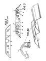
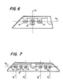
- FIG. 6 is a schematic view illustrating imaginary reference planes by which the relative positions of original and new sockets are described; and
- FIG. 7 is a schematic view illustrating an alternative set of reference planes.
- FIG. 1 shows a typical four foot long by two foot wide troffer, with a sheet metal, white-coated housing 1, and containing four
fluorescent tubes 2. Theballast compartment 3 lies along the center of the fixture.Sockets 4 at end 5 of the fixture support and provide electrical power to the fluorescent tubes. Similar sockets are provided at the opposite end. Wires bringing power to the sockets lie behind a protective sheet metal wire cover 6. - FIG. 2 shows in detail a typical configuration of the end wall 5 of a four-tube fluorescent fixture. The positions of the
fluorescent tubes 2 nearest to theballast compartment 3 are indicated. The outermost fluorescent tubes are removed to show thesockets 4. Conversion of a four-tube fixture of this type to energy-saving operation with only two inner fluorescent tubes, is practiced in the prior art, as represented for example by Crabtree U. S. Pat. No. 4,336,576. In Crabtree, one fluorescent tube of each pair is removed, and a new reflector is installed which is specially designed to produce relatively uniform illumination of a diffuser plate despite the removal of one-half of the total number of fluorescent tubes. A prevailing difficulty in such conversions will be appreciated from FIG. 2 of the present application. In many fixtures as in FIG. 2, there is too little space between the positions of the fluorescent tubes and the top and other surfaces of the housing to install a reflector which provides uniform and efficient light output across the entire surface area of the lighting apparatus. - In an embodiment of the present invention as shown in FIG. 3, uniform and efficient light output is achieved by installing two fluorescent tubes in
sockets 8 newly installed between the existing pairs ofsockets 4. The preferred location ofnew sockets 8 relative to the existingsockets 4, relative to thetop 7 of the housing, and relative to the other internal features of a fixture will vary depending upon the precise dimensions and layout of the particular lighting apparatus which is being converted. Likewise, the detailed configuration of thereflector 9 which is installed as part of the conversion influences the preferred location of the new sockets as also does the pattern of light which the converted fixture is intended to provide. In a preferred embodiment of this invention, the new sockets are located such that fluorescent tubes mounted therein are midway between the tubes which had been mounted before conversion in the preexisting pairs of sockets, further, the new sockets are placed such that tubes mounted therein are at the same distance from thetop 7 of the housing as were the four tubes prior to conversion. Where desired, however the positions of the new sockets can be such that the tubes therein are either closer to or further from thetop surface 7 of the housing. The present invention provides a measure of flexibility in the positioning of the fluorescent tubes to suit the requirements of the particular conversion. - In general, as shown in FIG. 6, at each end of the lighting apparatus, the
new sockets 8 for each new tube are positioned so as to be intersected by a first imaginary plane P₁, located between theoriginal sockets 4, and perpendicular to a second imaginary plane P₂ intersecting the original sockets. Thus the new sockets are generally between the old sockets, but may be located at the level of the old sockets, or somewhat above or below that level. Stating the relationship between new and old sockets another way with reference to FIG. 7, the originaltubular lamps 2 and 2a can be thought of as located on parallel axes A₁ and A₂ lying respectively in imaginary parallel planes P₃ and P₄ which are both perpendicular to a plane P₅ defined by said axes. Thenew sockets 8 for the new tubular bulb are mounted on a line parallel to said parallel axes A₁ and A₂ and between said imaginary parallel planes P₃ and P₄. In the case of a four-tube fluorescent lighting apparatus, as in FIG. 7, there are four original fluorescent tubes in a row on parallel axes A₂, A₁, A₃, and A₄ all lying in plane P₅ and in imaginary parallel planes P₄, P₃, P₆ and P₇. One of thenew sockets 8 is mounted between planes P₄ and P₃ and the other is mounted between planes P₆ and P₇. - In the embodiment of the invention shown in FIG. 3 the
new sockets 8 are mounted in the same manner as the preexisting sockets, so that the tubes are insertable from below. The new sockets are held in position by means of one or more screws 10 or other mechanical connectors inserted through holes in the body of the new sockets, or by means of contact cement, or by any other suitable means, - A feature of the present invention is that power is brought to the
new sockets 8 through cables 11 to which plugs 12 are attached. The plugs are inserted inpreexisting sockets 4 and make electrical contact therewith. To complete the electrical circuit to thenew sockets 8 correctly, plugs 12 must be inserted at opposite ends of the fixture in sockets which previously held opposite ends of an individual fluorescent tube. - In a preferred embodiment of the invention, the
new sockets 8 are symmetrical about their long axis so that they may make connection with equal facility tosocket 4 which is to their left, as in the left side reflective compartment of the fixture shown in FIG. 3, or to their right as in the right side reflective compartment of the fixture shown in FIG. 3. - Electrical connections can be made to the new sockets in other ways. For example, wires originally connected to deliver electric current to original sockets can be disconnected from the original sockets and reconnected to the new sockets, either directly, or through additional lengths of wire connected from the original wires to the new sockets. Alternatively, the new sockets can be connected directly to the ballast and to the line. Still another way to make electrical connections to a socket is to remove one of the adjacent original sockets, and connect the new socket to the wiring behind the wire cover through the opening exposed when the original socket is removed.
- A feature of the
reflector 9 in the embodiment of the invention in FIG. 3 is that its surface is highly reflective. The reflector in this embodiment is a single sheet of material, with or without a reflective coating or film laminated or otherwise attached thereto, shaped suitably to fit within the size constraints of the existing fixture and designed to yield high efficiency and the required distribution of light output. The reflector is attached to thetop surface 7 of the fixture, or to any other convenient part of the housing or frame of the lighting apparatus. Attachment may be by any convenient mechanical or chemical means. The reflector can even be attached, by means of clips, directly to the newly mounted fluorescent tube. The reflective surface may feature discrete bends in otherwise plane surfaces, or may vary in curvature from point to point without discontinuities, or both. - In FIG. 3A the parts used to convert the fixture shown schematically in FIG. 3 are illustrated. In the example of converting a four-tube fixture to operation with two tubes, parts required are one
reflector 9, four new socket units each comprising asocket 8, a cable 11 and aplug 12, and suitable means of connection, not illustrated. Thesocket 8 is preferably provided with through holes for fasteners, such as sheet metal screws, which secure the socket to a supporting surface in the lighting apparatus. - In FIG. 4 a further preferred embodiment of the invention is shown. Each reflective compartment of the fixture is fitted with a
reflector 14. Further, aclip 15 is installed at eachnew socket 8 by the same mechanical or chemical connectors used to attach the new sockets to the end walls of the fixture. The clips are positioned so that they press with moderate force against thetop 7 of the fixture, in which position they serve to hold in place the newly installed reflective material. In this preferred embodiment of the invention, theclips 15 fulfill several functions of considerable utility. - Securing the clips in position with the same means of connection used to attach the new sockets to the end walls of the fixture minimizes the number of connections required for conversion, thereby saving the effort, time and cost of making such further connections. Further, in an embodiment where screws are used to make the installation, use of the clips eliminates the tiring and time consuming requirement of working above one's head drilling in the top surface of the fixture. Further, the predetermined size of the clips serves to position the reflective material precisely relative to the newly installed fluorescent tubes, so that no deviation from the results designed for can arise from improper installation.
- Since the reflective material is held in position by pressure from clips exerted against the reflector pressed against the top surface of the fixture, rather than by more permanent other mechanical or chemical means, a number of further advantages arise. For example, the position of the reflective material can be readily adjusted during the course of installation for optimum fit. In the case of reflectors on the left and right hand sides of the ballast compartment which are required to meet precisely along their entire lengths, the reflectors can easily be so adjusted. Also, the ease with which the reflective material can be removed from the retaining clips facilitates access to the ballast compartment, which access is occasionally required to replace failed ballasts.
- FIG. 4A shows the materials used to convert the fixture in FIG. 4. In the example of converting a four-tube fixture to operation with two tubes, materials required are two
reflectors 16, four plug/wire/socket units 16, fourclips 15, and four or eight screws, rivets or other fasteners (not shown). In a preferred embodiment, the reflectors 17 have flat surfaces in those areas where the clips make contact. - In the embodiment of the invention shown in FIG. 4, the
new sockets 8 are mounted for sideways tube insertion whereas the preexisting sockets are mounted for vertical tube insertion. An advantage of this embodiment is that more space is available to raise or lower the position of the sideways mounted sockets relative to thetop surface 7 of the housing. - FIG. 5 illustrates the disposition in a preferred embodiment of the present invention of
new sockets 8, clips 15, wire covers 6, thetop surface 7 of the fixture and thereflective material 9. To facilitate installation and removal of the reflector, the relationships between the overall length of the reflector from end 18 to end 18a, the distance between theouter limits clips 15 and the distance between thepoints 20 and 20a where the wire covers meet the top surface of the fixture, are important and must bear correct relationship one to another. In the preferred embodiment there is sufficient distance betweenpoints points 20a and 19a to allow the reflector to slide up against the wire cover 6 at one end of the fixture, and thereby become completely free of the clip at the other end. In this way, insertion and removal of the reflective material is readily accomplished. - While preferred embodiments of the apparatus of the invention have been disclosed, modifications may be made thereto by a person skilled in the art without departing from the spirit of this invention, and it is intended to protect by Letters Patent all forms of the invention falling within the scope of the following claims.
Claims (5)
(a) removing said tubes from said original sockets;
(b) leaving the original sockets at opposite ends of at least one of said tubes of each pair in their original positions and connected to said original wiring connections, whereby there are at least two remaining original sockets for each pair of original tubes;
(c) securing, in the lighting apparatus, a pair of new sockets corresponding to each original pair of tubes, so that the sockets of each of said pair of new sockets are located opposite each other on a line parallel to said parallel axes and between the imaginary parallel planes in which the axes of the corresponding original pair of tubes were located;
(d) electrically connecting said new sockets to said original wiring connections by connecting each of said new sockets through an adapter plug to one of said remaining original sockets; and
(e) installing a fluorescent tube in each said pair of new sockets;
whereby one fluorescent tube is substituted for each pair of original tubes.
Applications Claiming Priority (2)
| Application Number | Priority Date | Filing Date | Title |
|---|---|---|---|
| US840441 | 1986-03-17 | ||
| US06/840,441 US4674016A (en) | 1986-03-17 | 1986-03-17 | Lighting apparatus |
Publications (2)
| Publication Number | Publication Date |
|---|---|
| EP0238010A2 true EP0238010A2 (en) | 1987-09-23 |
| EP0238010A3 EP0238010A3 (en) | 1989-05-31 |
Family
ID=25282392
Family Applications (1)
| Application Number | Title | Priority Date | Filing Date |
|---|---|---|---|
| EP87103762A Withdrawn EP0238010A3 (en) | 1986-03-17 | 1987-03-16 | Lighting apparatus |
Country Status (5)
| Country | Link |
|---|---|
| US (1) | US4674016A (en) |
| EP (1) | EP0238010A3 (en) |
| JP (1) | JPS62264503A (en) |
| CA (1) | CA1259975A (en) |
| GB (1) | GB2188139A (en) |
Cited By (1)
| Publication number | Priority date | Publication date | Assignee | Title |
|---|---|---|---|---|
| DE19817222A1 (en) * | 1998-04-17 | 1999-10-28 | Fraenkische Leuchten Gmbh | Lamp housing for multi-light fitting esp. integrated in room ceiling with 2 side walls arranged lying opposite each other for arrangement of lamp holders with respectively two lying opposite each other |
Families Citing this family (16)
| Publication number | Priority date | Publication date | Assignee | Title |
|---|---|---|---|---|
| US4967324A (en) * | 1987-06-26 | 1990-10-30 | Lascon Lighting Industries (Proprietary) Limited | Pivotable luminaire |
| NL8800149A (en) * | 1988-01-22 | 1989-08-16 | Poot Lichtenergie | LUMINAIRE FOR GLASS GARDEN LIGHTING. |
| JPH0233803A (en) * | 1988-07-22 | 1990-02-05 | Ushio Supetsukusu:Kk | Lighting device |
| US4928209A (en) * | 1988-08-31 | 1990-05-22 | Mirrorlite, Inc. | Lighting apparatus |
| JPH0455367Y2 (en) * | 1989-10-31 | 1992-12-25 | ||
| US5111370A (en) * | 1991-02-21 | 1992-05-05 | Clark Walter B | Device and method for converting a down-light into an up-light |
| US5381321A (en) * | 1992-06-02 | 1995-01-10 | Service Machine Co. | Luminaire for hazardous atmospheres and explosion proof enclosure for power supply therefor |
| EP0828968A1 (en) * | 1996-03-22 | 1998-03-18 | Koninklijke Philips Electronics N.V. | Irradiation device |
| DE19641343A1 (en) * | 1996-10-08 | 1998-04-09 | Thorn Licht Gmbh | Head-piece for high-bay strip-lighting fluorescent lighting |
| US6619815B2 (en) | 2001-10-11 | 2003-09-16 | Liteco | Low-profile light fixture for recreational vehicles |
| CA2383182C (en) * | 2002-04-23 | 2010-07-20 | Ireneusz Witkowski | Energy efficient lighting apparatus and use thereof |
| USD538462S1 (en) | 2004-04-19 | 2007-03-13 | Orion Energy Systems Ltd. | Fluorescent tube light low bay reflector |
| WO2009004841A1 (en) * | 2007-07-04 | 2009-01-08 | Sharp Kabushiki Kaisha | Lighting apparatus, display unit, and television receiver |
| US8092037B2 (en) | 2008-08-22 | 2012-01-10 | Philips Electronics North America Corporation | Fluorescent light fixture retrofit kit |
| US20100188851A1 (en) * | 2009-01-28 | 2010-07-29 | John Timothy Sims | Lighting Retrofit |
| US9080777B2 (en) | 2012-01-31 | 2015-07-14 | Schwank, Ltd. | Reflector for radiant tube heater |
Citations (3)
| Publication number | Priority date | Publication date | Assignee | Title |
|---|---|---|---|---|
| US4336576A (en) * | 1980-04-07 | 1982-06-22 | Crabtree Daniel B | Lighting apparatus |
| US4536830A (en) * | 1984-07-26 | 1985-08-20 | Wisniewski Gregory G | Reflector assembly for lamp fixtures |
| EP0151850A2 (en) * | 1984-02-07 | 1985-08-21 | Maximum Technology | Reflector systems for lighting fixtures and methods of installing such system |
Family Cites Families (3)
| Publication number | Priority date | Publication date | Assignee | Title |
|---|---|---|---|---|
| US4317069A (en) * | 1980-01-29 | 1982-02-23 | Burgess David E | Means and method for controlling lumen output and power consumption of phosphor excitable lamps |
| US4388675A (en) * | 1980-12-15 | 1983-06-14 | Ian Lewin | Indirect lighting fixture |
| CA1186366A (en) * | 1982-01-22 | 1985-04-30 | David E. Burgess | Means and method for controlling lumen output and power consumption of phosphor excitable lamps |
-
1986
- 1986-03-17 US US06/840,441 patent/US4674016A/en not_active Expired - Fee Related
- 1986-05-22 GB GB08612542A patent/GB2188139A/en not_active Withdrawn
- 1986-06-23 CA CA000512167A patent/CA1259975A/en not_active Expired
-
1987
- 1987-03-16 EP EP87103762A patent/EP0238010A3/en not_active Withdrawn
- 1987-03-17 JP JP62060232A patent/JPS62264503A/en active Pending
Patent Citations (3)
| Publication number | Priority date | Publication date | Assignee | Title |
|---|---|---|---|---|
| US4336576A (en) * | 1980-04-07 | 1982-06-22 | Crabtree Daniel B | Lighting apparatus |
| EP0151850A2 (en) * | 1984-02-07 | 1985-08-21 | Maximum Technology | Reflector systems for lighting fixtures and methods of installing such system |
| US4536830A (en) * | 1984-07-26 | 1985-08-20 | Wisniewski Gregory G | Reflector assembly for lamp fixtures |
Cited By (2)
| Publication number | Priority date | Publication date | Assignee | Title |
|---|---|---|---|---|
| DE19817222A1 (en) * | 1998-04-17 | 1999-10-28 | Fraenkische Leuchten Gmbh | Lamp housing for multi-light fitting esp. integrated in room ceiling with 2 side walls arranged lying opposite each other for arrangement of lamp holders with respectively two lying opposite each other |
| DE19817222B4 (en) * | 1998-04-17 | 2004-02-19 | Regiolux Gmbh | Luminaire housing for a multi-lamp luminaire and method for producing the luminaire housing |
Also Published As
| Publication number | Publication date |
|---|---|
| EP0238010A3 (en) | 1989-05-31 |
| GB2188139A (en) | 1987-09-23 |
| CA1259975A (en) | 1989-09-26 |
| JPS62264503A (en) | 1987-11-17 |
| US4674016A (en) | 1987-06-16 |
| GB8612542D0 (en) | 1986-07-02 |
Similar Documents
| Publication | Publication Date | Title |
|---|---|---|
| US4674016A (en) | Lighting apparatus | |
| US6585396B1 (en) | Fluorescent hanging light fixture | |
| JP3258671B2 (en) | Road lighting equipment | |
| US4928209A (en) | Lighting apparatus | |
| US5580158A (en) | Retrofit light fixture | |
| US6135620A (en) | CCFL illuminated device | |
| US6793381B2 (en) | CCFL illuminated device and method of use | |
| CA2118474A1 (en) | Florescent Light Fixture Assembly | |
| CA2677328A1 (en) | Retrofit recessed fluorescent strip fixture and method | |
| CA2074314A1 (en) | Retro-Fit Lighting Fixture and Method of Retro-Fit | |
| US5585688A (en) | Compact fluorescent lamp | |
| US4807099A (en) | Lighting fixtures | |
| CA2037712A1 (en) | Cornice lighting system | |
| AU714535B2 (en) | Converter housing | |
| EP0374511A3 (en) | Heating lamp assembly for ccvd reactors | |
| CA2058738C (en) | High efficiency illumination system | |
| CA2390805A1 (en) | High bay compact fluorescent light fixture | |
| CN2282640Y (en) | Fluorescent lamp with V-shaped reflecting convex surface lamp socket | |
| JP2592163B2 (en) | lighting equipment | |
| CN210128259U (en) | Strip-shaped lamp and strip-shaped lamp combination | |
| CN219014173U (en) | LED lighting lamp | |
| CN217584205U (en) | Ultra-thin down lamp with special outlet structure | |
| CN210717317U (en) | Energy-saving outdoor lighting lamp convenient to installation | |
| CN220669261U (en) | Point light source lighting module with variable beam angle | |
| CN220379540U (en) | Modularized LED street lamp |
Legal Events
| Date | Code | Title | Description |
|---|---|---|---|
| PUAI | Public reference made under article 153(3) epc to a published international application that has entered the european phase |
Free format text: ORIGINAL CODE: 0009012 |
|
| AK | Designated contracting states |
Kind code of ref document: A2 Designated state(s): AT BE CH DE FR GB IT LI NL SE |
|
| PUAL | Search report despatched |
Free format text: ORIGINAL CODE: 0009013 |
|
| AK | Designated contracting states |
Kind code of ref document: A3 Designated state(s): AT BE CH DE FR GB IT LI NL SE |
|
| 17P | Request for examination filed |
Effective date: 19891018 |
|
| 17Q | First examination report despatched |
Effective date: 19910812 |
|
| STAA | Information on the status of an ep patent application or granted ep patent |
Free format text: STATUS: THE APPLICATION IS DEEMED TO BE WITHDRAWN |
|
| 18D | Application deemed to be withdrawn |
Effective date: 19911224 |