EP0237989B1 - Differential coding apparatus having an optimum predicted value determining circuit - Google Patents
Differential coding apparatus having an optimum predicted value determining circuit Download PDFInfo
- Publication number
- EP0237989B1 EP0237989B1 EP19870103701 EP87103701A EP0237989B1 EP 0237989 B1 EP0237989 B1 EP 0237989B1 EP 19870103701 EP19870103701 EP 19870103701 EP 87103701 A EP87103701 A EP 87103701A EP 0237989 B1 EP0237989 B1 EP 0237989B1
- Authority
- EP
- European Patent Office
- Prior art keywords
- value
- predicted value
- circuit
- optimum
- predicted
- Prior art date
- Legal status (The legal status is an assumption and is not a legal conclusion. Google has not performed a legal analysis and makes no representation as to the accuracy of the status listed.)
- Expired - Lifetime
Links
Images

Classifications
-
- H—ELECTRICITY
- H04—ELECTRIC COMMUNICATION TECHNIQUE
- H04N—PICTORIAL COMMUNICATION, e.g. TELEVISION
- H04N19/00—Methods or arrangements for coding, decoding, compressing or decompressing digital video signals
- H04N19/50—Methods or arrangements for coding, decoding, compressing or decompressing digital video signals using predictive coding
- H04N19/503—Methods or arrangements for coding, decoding, compressing or decompressing digital video signals using predictive coding involving temporal prediction
Definitions
- the present invention relates to a differential coding apparatus comprising predicted value producing means for producing a plurality of predicted values with respect to input data; determining means for determining an optimum predicted value from said plurality of predicted values; and means for selecting one of said predicted values as the optimum predicted value in accordance with the determined result.
- Such apparatus may be of a fast video signal such as a TV signal.
- Such apparatus is known from US-A-4 437 119 and US-A-4 546 386.
- a differential coding apparatus for carrying out the differential coding of a fast video signal such as a TV signal to be transmitted.
- a differential coding apparatus employing an intraframe ⁇ interframe differential coding is known and used as the differential coding apparatus for the TV signal.
- This differential coding apparatus has an intraframe prediction circuit and an interframe prediction circuit, and adaptively selects one of these circuits in response to the movement of a picture to be coded, so that a signal output by the selected circuit can be used as an optimum predicted value.
- the intraframe prediction circuit uses, for example, a previous value prediction in which a predicted value of a pixel to be coded is produced on the basis of a reference pixel just prior to the pixel to be coded on the same horizontal scanning line.
- a time needed for producing the predicted value of the pixel to be coded on the basis of data of the reference pixel after such data was obtained becomes very short, and accordingly, the determination of the optimum predicted value must be carried out at a high speed. Therefore, in general, the logical elements used in the apparatus must be able to operate at a high speed.
- one object of the present invention is to provide a differential coding apparatus in which the determination of the optimum predicted value can be carried out at a high speed without using a high speed processing type logical element.
- the apparatus initially defined is characterized in that the predicted value producing means and the determining means are arranged to carry out processing in parallel.
- Fig. 1 is a block diagram showing a differential coding apparatus of the prior art
- Fig. 2 is a drawing for explaining the intraframe previous value prediction
- Fig. 3 is a time chart for explaining the operation of the apparatus shown in Fig. 1
- Fig. 4 is a block diagram showing an embodiment of the differential coding apparatus according to the present invention
- Figs. 5-9 are drawings for explaining the operation of the apparatus shown in Fig. 4
- Fig. l0 is a block diagram showing another embodiment according to the present invention.
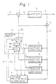
- Figure l is a block diagram showing a differential coding apparatus of the prior art in which an intraframe ⁇ interframe adaptive differential coding is carried out.
- the differential coding apparatus comprises a subtracter l for subtracting an optimum predicted value X ⁇ 0 from an input signal X to obtain a prediction error d ; a quantizer 2 for quantizing the predicted error d output from the subtracter l to produce a quantized predicted error ⁇ (referred to as a quantized value ⁇ hereinafter); an adder for adding the quantized value ⁇ and the optimum predicted value X ⁇ 0 to produce a local decoded signal X ⁇ ; predictive function computing circuits 4, 5, and 6 which produce predicted values X ⁇ I , X ⁇ M , and X ⁇ B obtained by different prediction manner, on the basis of the local decoded signal X ⁇ output from the adder 3, respectively; an optimum predicted value determining circuit 7 for determining the optimum predicted value X ⁇ 0 from predicted values X ⁇ I , X ⁇ M , and
- the intraframe ⁇ interframe adaptive differential coding employed in this differential coding apparatus is adapted as an international standard of the CCITT, in which the differential coding apparatus has an intraframe prediction circuit and an interframe prediction circuit and adaptively selects one of those circuits in response to the movement of a picture and uses the output signal thereof as an optimum predicted value.
- the predictive function computing circuit 4 carries out the intraframe previous value prediction in which, as shown in Fig. 2, a pixel X(i) to be coded is predicted on the basis of a reference pixel X(i-l) just prior to the pixel X(i) on the same horizontal scanning line.
- This prediction is normally a linear prediction in which the predicted value X(î) is obtained by multiplying the reference pixel X(i-l) by a prediction coefficient, and the predictive function computing circuit 4 outputs the predicted value X ⁇ I of the intraframe previous value.
- the predictive function computing circuit 5 carries out the interframe prediction for the movement compensation to output the predicted value X ⁇ M of the movement compensation.
- the predictive function computing circuit 6 carries out the interframe background prediction to output the background predicted value X B .
- the operation of the apparatus shown in Fig. l is as follows.
- the optimum predicted value X ⁇ 0 is subtracted from the input signal X at the subtracter l to produce the prediction error d .
- the prediction error d is then quantized by the quantizer 2 to produce the quantized value ⁇ .
- the quantized value ⁇ is sent to the transmitting unit (not shown), and at the same time, to the adder 3 to be added to the optimum predicted value X ⁇ 0 to produce the local decoded signal X ⁇ .
- the local decoded signal X ⁇ is input to predictive function computing circuits 4, 5, and 6 to produce predicted values X ⁇ I , X ⁇ M , and X ⁇ B , respectively, which are then input to the selecting circuit 8 and the optimum predicted value determining circuit 7.
- the determining circuit 7 subtracts each predicted value X ⁇ I , X ⁇ M , and X ⁇ B from the local decoded signal X ⁇ , respectively, then compares the subtracted results to determine the optimum predicted value having a minimum subtraction result from those predicted values X ⁇ I , X ⁇ M , and X ⁇ B .
- the determining circuit 7 then outputs selecting signals S1 and S2 to switch selectors 8l and 82 so that the optimum predicted value X ⁇ 0 is output from the selecting circuit 8 to the subtracter l and the adder 3.
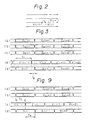
- Figure 3 is a time chart for explaining the operation of the above-described apparatus.
- (a) denotes a change timing of the predicted value X ⁇ I ;
- (b) a change timing of the predicted value X ⁇ M ;
- (c) a change timing of the predicted value X ⁇ B ;
- (d) a change timing of the local decoded signal X ⁇ ;
- (e) a change timing of the selecting signals S1 and S2.
- the determining circuit 7 determines a next optimum predicted value X ⁇ 0(i+l) with respect to predicted values X ⁇ I (i), X ⁇ M (i), and X ⁇ B (i) at the next timing, the local decoded signal X ⁇ (i) must be confirmed with respect to the current optimum predicted value X ⁇ 0(i), and the optimum predicted value X ⁇ 0(i+l) determined by subtracting each of the predicted values X ⁇ I (i), X ⁇ M (i), and X ⁇ B (i) from the local decoded signal X ⁇ (i), and the subtracted results then compared with one another.
- a delay time T1 from a time point of the change of the predicted values X ⁇ I (i), X ⁇ M (i), and X ⁇ B (i) until the confirmation of the local decoded signal X ⁇ (i-l), is a sum of signal delay times occurring at the selecting circuit 8, the subtracter l, the quantizer 2, and the adder 3.
- a delay time T2 after the confirmation of the local decoded signal X ⁇ (i) until the determining circuit 7 has determined the optimum predicted value, to output the selecting signal S(i+l), is a sum of the time for subtracting each of the predicted values X ⁇ I (i), X ⁇ M (i), and X ⁇ B (i) from the local decoded signal X ⁇ (i) and the time for comparing the subtracted results.
- a sum of the time T1 is needed for confirming the local decoded signal X ⁇ (i) with respect to above-mentioned predicted values, and of the time T2 for determining the optimum predicted value X ⁇ 0(i+l) on the basis of the confirmed local decoded signal X ⁇ (i).
- the predicting operation When, for example, the intraframe prediction by the previous value for the fast TV signal is carried out, the predicting operation must be carried out at a high speed, since this intraframe prediction predicts the predicted value of the pixel X(i) to be coded by using the reference pixel X(i-l) just prior to the pixel X(i) on the same horizontal scanning line. Therefore, in the prior art, the arithmetic circuit of the differential coding apparatus uses high speed processing type logical elements. However, these high speed processing type logical elements are expensive and consume much electric power, and accordingly must have a large size as a heat countermeasure. Further the high speed processing type logical element has less durability against noise than the low speed processing type logical element.
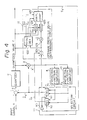
- Figure 4 is a block diagram showing an embodiment of the differential coding apparatus according to the present invention.
- l denotes a subtracter for subtracting an optimum predicted value X ⁇ 0 from an input signal X to produce a prediction error d; 2, a quantizer for quantizing the prediction error d to produce a quantized value ⁇ ; 3, an adder for adding the quantized value ⁇ and the optimum predicted value X ⁇ 0 to produce a local decoded signal X'; 4, a predictive function computing circuit for carrying out the intraframe prediction by the previous value on the basis of the local decoded signal X' to produce a predicted value X ⁇ I ; 10, a predictive function computing circuit for carrying out the interframe prediction on the basis of the local decoded signal X' to produce a predicted value X ⁇ x : 11, a selecting circuit which selects one of the predicted values X ⁇ I and X ⁇ x as the optimum predicted value X ⁇ 0 to be output, and at the same time outputs the non-optimum predicted value
- the selecting circuit 11 comprises two selectors 111 and 112 and an inverter 113.
- the selector 111 selects one of predicted values X ⁇ I and X ⁇ x as the optimum predicted value X ⁇ 0 to be output to the subtractor 1, the adder 3, and determining circuit 12 in response to the selecting signal S3.
- the selector 112 selects the residuary other predicted value as the non-optimum predicted value X ⁇ n to be output to the determining circuit 12.
- the optimum predicted value determining circuit 12 comprises a subtracter 121, a sign detecting circuit 122, a level regulating circuit 123, absolute value measuring circuits 124 and 125, and an amplitude comparing circuit 126.
- the subtracter 121 subtracts the optimum predicted value X0 from the non-optimum predicted value X ⁇ n to output a difference value ( X ⁇ n - X ⁇ 0) to the sign detecting circuit l22 and the level regulating circuit l23.
- the sign detecting circuit l22 determines the sign of the values ⁇ and ( X ⁇ n - X ⁇ 0) to output a signal S10 indicating the sign of the difference value ( X ⁇ n - X ⁇ 0) to the absolute value measuring circuit l25 and the amplitude comparing circuit l26, a signal S11 for indicating the sign of the quantized error ⁇ to the amplitude comparing circuit l26, and a signal S12 for indicating whether or not the difference value ( X ⁇ n - X ⁇ 0) and the quantized value ⁇ have the same sign to the amplitude comparing circuit l26.
- the level regulating circuit l23 multiplies the difference value ( X ⁇ n - X ⁇ 0) by a coefficient of 1 ⁇ 2, using a bit-shift.
- the absolute value measuring circuit l24 measures an absolute value
- the absolute value measuring circuit l25 measures an absolute value
- the amplitude comparing circuit l26 carries out a comparison of the amplitudes of the quantized value ⁇ and the difference value ( X ⁇ n - X ⁇ 0) on the basis of absolute values
- the operation of the embodiment shown in Fig. 4 will be described hereinafter.
- the optimum predicted value X ⁇ 0 is subtracted from the input signal X at the subtracter l to produce the prediction error d , which is then quantized at the quantizer 2 to produce the quantized value ⁇
- the quantized value ⁇ is added to the optimum predicted value X ⁇ 0 at the adder 3 to produce the local decoded signal X ⁇ .
- the computing circuits 4 and l0 produce predicted values X ⁇ I and X ⁇ X on the basis of the local decoded signal X ⁇ respectively.
- the determining circuit l2 determines which computing circuits 4 and l0 will output the optimum predicted value with respect to the input signal which is input at the next timing, on the basis of the quantized value ⁇ and the difference value ( X ⁇ n - X ⁇ 0) , and outputs the selecting signal S3 according to the determined result to control the selection of the selecting circuit ll.
- the optimum predicted value X ⁇ 0(i+l) with respect to the input signal X(i+l) of the next timing is determined on the basis of predicted values X ⁇ I (i) and X ⁇ X (i) obtained from the previous input signal X(i).
- the prediction is not degraded, as a correlation between the previous input signal X(i) and the following input signal X(i+l) is close.
- the quantized value ⁇ output from the quantizer 2 may be deemed as a difference value (X ⁇ - X ⁇ 0) between the local decoded signal X ⁇ and the optimum predicted value X0.
- the operation of (X ⁇ - X ⁇ 0) - (X n - X ⁇ 0) by using the difference value ( X ⁇ n - X ⁇ 0) obtained by the subtracter l2l on the basis of values X ⁇ n and X ⁇ 0 output from the selecting circuit ll yields a value ( X ⁇ ⁇ - X ⁇ n ) .
- the optimum predicted value X0 is one of predicted values X ⁇ I and X ⁇ X which gives smaller difference values between the input signal X and each of the predicted values X I and X ⁇ X , i.e., (X ⁇ - X ⁇ I ) and (X ⁇ - X ⁇ X ) .
- the predictive function computing circuit whose output is selected as the optimum predicted value X ⁇ 0 (referred to as an optimum computing circuit hereinafter) at the current timing, will continue to be the optimum computing circuit with respect to the input signal input at the next timing. If the optimum computing circuit is selected continuously at the next timing, the selecting circuit ll does not carry out the switching.
- the selecting circuit ll selects the output of the current non-optimum computing circuit as the optimum predicted value at the next timing.
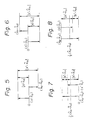
- the absolute value of the value (X ⁇ - X ⁇ 0) is smaller than that of the value (X ⁇ - X ⁇ n ) , therefore the predicted value output from the current optimum computing circuit is selected continuously as the optimum predicted value at the next timing.
- the predicted value output from the current optimum computing circuit is selected as the optimum predicted value at the next timing.
- Figure 8 shows the case when the value ( X ⁇ n - X ⁇ 0) is negative.
- the relationships are as follows.
- the amplitude comparing circuit l26 carries out the aforementioned determination on the basis of the input signals S10 and S12 and input absolute values, then outputs the selecting signal S3 in accordance with the determination.
- the optimum predicted value determining circuit l2 can determine which predictive function computing circuit will output the optimum predicted value at the next timing, on the basis of the quantized value ⁇ , the optimum predicted value X ⁇ 0 , and the non-optimum predicted value X ⁇ n , without using the local decoded signal X ⁇ .
- the processing speed of the differential coding apparatus is increased, which will be explained in detail with reference to Fig. 9.
- Figure 9 is a time chart for explaining the operation of the above-described embodiment.
- (a) denotes a change timing of the predicted value X I ;
- (b) a change timing of the predicted value X X ;
- (c) a change timing of the quantized value ⁇ ;
- (d) a change timing of the selecting signal S3.
- a time readed for the prediction operation which is from when the computing circuits output predicted values X I (i) and X X (i) to when the determining circuit l2 determines the next optimum predicted value and outputs the selecting signal S(i+l), is a sum of a time T3 from the confirmation of predicted values X I (i) and X X (i) until the confirmation of the quantized value ⁇ and a time T4 needed for determining the optimum predicted value on the basis of the confirmed quantized value.
- the time T3 is a sum of each signal delay time occurring at the selecting circuit ll, the subtracter l, and the quantizer 2. Comparing this time T3 with the prior art, the apparatus of the present invention operates faster than the prior art apparatus shown in Fig. l by a signal delay time caused at the adder 4, since the prior art apparatus must confirm the local decoded signal X ⁇ for the determination at the determining circuit 7, but the apparatus of the present invention only needs to confirm the quantized value ⁇ .
- the optimum predicted value determining circuit 7 carries out the subtraction between the local decoded signal X ⁇ and each of predicted values X I , X M , and X B , and then the amplitude comparison of the results obtained by above-mentioned subtraction, after the confirmation of the local decoded signal X ⁇ .
- the difference value ( X ⁇ n - X ⁇ 0) used for determining the optimum predicted value has already been calculated before the confirmation of the quantized value ⁇ , therefore it is sufficient for the determining circuit l2 to carry out the amplitude comparison after the confirmation of the quantized value ⁇ .
- the process for obtaining the quantized value ⁇ with respect to the confirmed predicted values X ⁇ I and X ⁇ x , and the process for obtaining the difference value ( X ⁇ n - X ⁇ o ) between the confirmed predicted values X I and X ⁇ x , are carried out in parallel, and the determination of the optimum predicted value is then carried out by comparing the obtained quantized value and the obtained difference value.
- the differential coding circuit of the present invention operates faster than the prior art apparatus by the signal delay time caused at the adder 4 and the time used for the subtraction at the determining circuit 7.
- one predictive function computing circuit carries out the intraframe prediction and the other circuit carries out the interframe prediction.
- this is not a limitation, in that the case in which both computing circuits carry out the intraframe prediction is possible.
- Figure l0 shows another embodiment in which, as in the apparatus of Fig. l, the intraframe prediction, the interframe movement compensation prediction, and the interframe background prediction are carried out.
- the same reference numbers as in Fig. l denote the same components.
- the local decoded signal X ⁇ output from the adder 3 is input to the predictive function computing circuits 4, 5, and 6, and the optimum predicted value determining circuit 7.
- Predicted values X ⁇ M and X ⁇ B output from computing circuits 5 and 6 are input to a selector l4 and the optimum predicted value determining circuit 7.
- the determining circuit 7 selects one of the predicted values X ⁇ M and X ⁇ B as the optimum predicted value in the same way as described in the prior art, and outputs a selecting signal S5.
- the selector l4 sends the selected predicted value to the selecting circuit ll.
- the other operations of this embodiment are the same as that of Fig. 4.
- the selecting circuit ll selects one of two input predicted values as the optimum predicted value in response to the selecting signal output from the determining circuit l2.
- the optimum predicted value determining circuit 7 determines the optimum predicted value on the basis of the local decoded signal X ⁇ .
- the determination of the optimum predicted value for the input signal on the current frame is carried out on the basis of data of the previous frame, since computing circuits 5 and 5 carry out the interframe prediction. Accordingly, the processing time for determination is long enough, and allows the apparatus to be constituted by using logical elements for low speed processing in spite of the high speed input signal.
Landscapes
- Engineering & Computer Science (AREA)
- Multimedia (AREA)
- Signal Processing (AREA)
- Compression, Expansion, Code Conversion, And Decoders (AREA)
Description
- The present invention relates to a differential coding apparatus comprising predicted value producing means for producing a plurality of predicted values with respect to input data; determining means for determining an optimum predicted value from said plurality of predicted values; and means for selecting one of said predicted values as the optimum predicted value in accordance with the determined result. Such apparatus may be of a fast video signal such as a TV signal. Such apparatus is known from US-A-4 437 119 and US-A-4 546 386.
- Recently, with the development of picture display techniques, it has become necessary to provide a differential coding apparatus for carrying out the differential coding of a fast video signal such as a TV signal to be transmitted. A differential coding apparatus employing an intraframe·interframe differential coding is known and used as the differential coding apparatus for the TV signal. This differential coding apparatus has an intraframe prediction circuit and an interframe prediction circuit, and adaptively selects one of these circuits in response to the movement of a picture to be coded, so that a signal output by the selected circuit can be used as an optimum predicted value.
- The intraframe prediction circuit uses, for example, a previous value prediction in which a predicted value of a pixel to be coded is produced on the basis of a reference pixel just prior to the pixel to be coded on the same horizontal scanning line. In this case, a time needed for producing the predicted value of the pixel to be coded on the basis of data of the reference pixel after such data was obtained becomes very short, and accordingly, the determination of the optimum predicted value must be carried out at a high speed. Therefore, in general, the logical elements used in the apparatus must be able to operate at a high speed.
- However, such logical elements for high speed operation are expensive and consume much electric power, and accordingly, must have a large size as a heat countermeasure. Further, the high speed processing type logical elements have less durability against noise than low speed processing type logical elements.
- Accordingly, one object of the present invention is to provide a differential coding apparatus in which the determination of the optimum predicted value can be carried out at a high speed without using a high speed processing type logical element.
- According to the invention, the apparatus initially defined is characterized in that the predicted value producing means and the determining means are arranged to carry out processing in parallel.
- Embodiments according to the present invention will now be described with reference to the accompanying drawings, in which;
Fig. 1 is a block diagram showing a differential coding apparatus of the prior art;
Fig. 2 is a drawing for explaining the intraframe previous value prediction;
Fig. 3 is a time chart for explaining the operation of the apparatus shown in Fig. 1;
Fig. 4 is a block diagram showing an embodiment of the differential coding apparatus according to the present invention;
Figs. 5-9 are drawings for explaining the operation of the apparatus shown in Fig. 4; and,
Fig. l0 is a block diagram showing another embodiment according to the present invention. - For a better understanding of the preferred embodiments of the present invention, the problems in the prior art will first be explained in detail with reference to Figs. l to 3.
- Figure l is a block diagram showing a differential coding apparatus of the prior art in which an intraframe·interframe adaptive differential coding is carried out. In Fig. l, the differential coding apparatus comprises a subtracter l for subtracting an optimum predicted value X̂₀ from an input signal X to obtain a prediction error d; a
quantizer 2 for quantizing the predicted error d output from the subtracter l to produce a quantized predicted error ε (referred to as a quantized value ε hereinafter); an adder for adding the quantized value ε and the optimum predicted value X̂₀ to produce a local decoded signal Xʹ; predictivefunction computing circuits adder 3, respectively; an optimum predicted value determining circuit 7 for determining the optimum predicted value X̂₀ from predicted values X̂I , X̂M , and X̂B on the basis of the local decoded signal Xʹ and predicted values X̂I , X̂M , and X̂B to output selecting signals S₁ and S₂; and aselecting circuit 8 for selecting the optimum predicted value from predicted values X̂I , X̂M , and X̂B in response to selecting signals S₁ and S₂ to be output to the subtracter l and theadder 3. The selectingcircuit 8 comprises twoselectors 8l and 82, and a flip-flop 83. - The intraframe·interframe adaptive differential coding employed in this differential coding apparatus is adapted as an international standard of the CCITT, in which the differential coding apparatus has an intraframe prediction circuit and an interframe prediction circuit and adaptively selects one of those circuits in response to the movement of a picture and uses the output signal thereof as an optimum predicted value.
- The predictive
function computing circuit 4 carries out the intraframe previous value prediction in which, as shown in Fig. 2, a pixel X(i) to be coded is predicted on the basis of a reference pixel X(i-l) just prior to the pixel X(i) on the same horizontal scanning line. This prediction is normally a linear prediction in which the predicted value X(î) is obtained by multiplying the reference pixel X(i-l) by a prediction coefficient, and the predictivefunction computing circuit 4 outputs the predicted value X̂I of the intraframe previous value. - The predictive
function computing circuit 5 carries out the interframe prediction for the movement compensation to output the predicted value X̂M of the movement compensation. The predictivefunction computing circuit 6 carries out the interframe background prediction to output the background predicted value XB. - The operation of the apparatus shown in Fig. l is as follows. The optimum predicted value X̂₀ is subtracted from the input signal X at the subtracter l to produce the prediction error d. The prediction error d is then quantized by the
quantizer 2 to produce the quantized value ε. The quantized value ε is sent to the transmitting unit (not shown), and at the same time, to theadder 3 to be added to the optimum predicted value X̂₀ to produce the local decoded signal Xʹ. Note, it is possible to input the quantized value ε to theadder 3 via an inverting circuit having an inverted characteristic of thequantizer 2. - The local decoded signal Xʹ is input to predictive
function computing circuits circuit 8 and the optimum predicted value determining circuit 7. The determining circuit 7 subtracts each predicted value X̂I , X̂M , and X̂B from the local decoded signal Xʹ, respectively, then compares the subtracted results to determine the optimum predicted value having a minimum subtraction result from those predicted values X̂I , X̂M , and X̂B. The determining circuit 7 then outputs selecting signals S₁ and S₂ to switchselectors 8l and 82 so that the optimum predicted value X̂₀ is output from the selectingcircuit 8 to the subtracter l and theadder 3. - Figure 3 is a time chart for explaining the operation of the above-described apparatus. In Fig. 3, (a) denotes a change timing of the predicted value X̂I; (b), a change timing of the predicted value X̂M; (c), a change timing of the predicted value X̂B; (d), a change timing of the local decoded signal Xʹ; and (e), a change timing of the selecting signals S₁ and S₂.
- Assuming that predicted values X̂I(i), X̂M(i), and X̂B(i) are output from
computing circuits circuit 8 selects one of those values as the optimum predicted value X̂₀(i). When the determining circuit 7 determines a next optimum predicted value X̂₀(i+l) with respect to predicted values X̂I(i), X̂M(i), and X̂B(i) at the next timing, the local decoded signal Xʹ(i) must be confirmed with respect to the current optimum predicted value X̂₀(i), and the optimum predicted value X̂₀(i+l) determined by subtracting each of the predicted values X̂I(i), X̂M(i), and X̂B(i) from the local decoded signal Xʹ(i), and the subtracted results then compared with one another. - In this case, as shown in Fig. 3, a delay time T₁ from a time point of the change of the predicted values X̂I(i), X̂M(i), and X̂B(i) until the confirmation of the local decoded signal Xʹ(i-l), is a sum of signal delay times occurring at the
selecting circuit 8, the subtracter l, thequantizer 2, and theadder 3. Further, a delay time T₂ after the confirmation of the local decoded signal Xʹ(i) until the determining circuit 7 has determined the optimum predicted value, to output the selecting signal S(i+l), is a sum of the time for subtracting each of the predicted values X̂I(i), X̂M(i), and X̂B(i) from the local decoded signal Xʹ(i) and the time for comparing the subtracted results. As described above, to select the following optimum predicted value X̂₀(i+l) from the predicted values X̂I(i), X̂M(i) and X̂B , a sum of the time T₁ is needed for confirming the local decoded signal Xʹ(i) with respect to above-mentioned predicted values, and of the time T₂ for determining the optimum predicted value X̂₀(i+l) on the basis of the confirmed local decoded signal Xʹ(i). - When, for example, the intraframe prediction by the previous value for the fast TV signal is carried out, the predicting operation must be carried out at a high speed, since this intraframe prediction predicts the predicted value of the pixel X(i) to be coded by using the reference pixel X(i-l) just prior to the pixel X(i) on the same horizontal scanning line. Therefore, in the prior art, the arithmetic circuit of the differential coding apparatus uses high speed processing type logical elements. However, these high speed processing type logical elements are expensive and consume much electric power, and accordingly must have a large size as a heat countermeasure. Further the high speed processing type logical element has less durability against noise than the low speed processing type logical element.
- Preferred embodiments of the present invention are now described in detail with reference to Figures 4 to l0.
- Figure 4 is a block diagram showing an embodiment of the differential coding apparatus according to the present invention. In Fig. 4, l denotes a subtracter for subtracting an optimum predicted value X̂₀ from an input signal X to produce a prediction error d; 2, a quantizer for quantizing the prediction error d to produce a quantized value ε; 3, an adder for adding the quantized value ε and the optimum predicted value X̂₀ to produce a local decoded signal X'; 4, a predictive function computing circuit for carrying out the intraframe prediction by the previous value on the basis of the local decoded signal X' to produce a predicted value X̂I; 10, a predictive function computing circuit for carrying out the interframe prediction on the basis of the local decoded signal X' to produce a predicted value X̂x: 11, a selecting circuit which selects one of the predicted values X̂I and X̂x as the optimum predicted value X̂₀ to be output, and at the same time outputs the non-optimum predicted value X̂n which is not selected as the optimum predicted value X̂₀; 12, an optimum predicted value determining circuit, to which the optimum predicted value X̂₀ , the non-optimum predicted value X̂n , and the quantized value ε are input, for determining which of the predicted values output from
computing circuits circuit 11 so that theselecting circuit 11 selects the optimum predicted value X̂₀ from predicted values X̂I and X̂x. - The selecting
circuit 11 comprises twoselectors inverter 113. Theselector 111 selects one of predicted values X̂I and X̂x as the optimum predicted value X̂₀ to be output to thesubtractor 1, theadder 3, and determiningcircuit 12 in response to the selecting signal S₃. On the other hand, theselector 112 selects the residuary other predicted value as the non-optimum predicted value X̂n to be output to the determiningcircuit 12. - The optimum predicted
value determining circuit 12 comprises asubtracter 121, asign detecting circuit 122, a level regulatingcircuit 123, absolutevalue measuring circuits 124 and 125, and anamplitude comparing circuit 126. Thesubtracter 121 subtracts the optimum predicted value X₀ from the non-optimum predicted value X̂n to output a difference value


- The level regulating circuit l23 multiplies the difference value


 to be output to the amplitude comparing circuit l26. The amplitude comparing circuit l26 carries out a comparison of the amplitudes of the quantized value ε and the difference value


computing circuits 4 and l0 will output the optimum predicted value at the next timing, then outputs the selecting signal S₃ to the selecting circuit ll. - The operation of the embodiment shown in Fig. 4 will be described hereinafter. The optimum predicted value X̂₀ is subtracted from the input signal X at the subtracter l to produce the prediction error d, which is then quantized at the
quantizer 2 to produce the quantized value ε The quantized value ε is added to the optimum predicted value X̂₀ at theadder 3 to produce the local decoded signal Xʹ. Thecomputing circuits 4 and l0 produce predicted values X̂I and X̂X on the basis of the local decoded signal Xʹ respectively. - The determining circuit l2 determines which
computing circuits 4 and l0 will output the optimum predicted value with respect to the input signal which is input at the next timing, on the basis of the quantized value ε and the difference value , and outputs the selecting signal S₃ according to the determined result to control the selection of the selecting circuit ll. In this way, the optimum predicted value X̂₀(i+l) with respect to the input signal X(i+l) of the next timing is determined on the basis of predicted values X̂I(i) and X̂X(i) obtained from the previous input signal X(i). However, the prediction is not degraded, as a correlation between the previous input signal X(i) and the following input signal X(i+l) is close.
- An algorithm for determining the optimum predicted value at the determining circuit l2 will be explained hereinafter. The quantized value ε output from the
quantizer 2 may be deemed as a difference value


 . Accordingly, by comparing the amplitudes of the quantized value


- The amplitude comparisons between


- Second, the case where the quantized value ε and the difference value


- When
 is obtained. In this case, either Xn or X₀ may be selected as the optimum value. In this example, the predicted value of the current non-optimum computing circuit is selected as the optimum predicted value at the next timing, so that the selecting circuit is switched.
- When
 is obtained. Accordingly, the predicted value output from the current optimum computing circuit is selected as the optimum predicted value at the next timing.
- When
 is obtained. Accordingly, the predicted value output from the current non-optimum computing circuit is selected as the optimum predicted value at the next timing.
- Figure 8 shows the case when the value
 is negative. The relationships are as follows.
- When
 is obtained. Accordingly, as aforementioned, the predicted value output from the current non-optimum computing circuit is selected as the optimum predicted value at the next timing.
- When
 is obtained. Accordingly, the predicted value output from the current non-optimum computing circuit is selected as the optimum predicted value at the next timing.
- When
 is obtained. Accordingly, the predicted value output from the current optimum computing circuit is selected as the optimum predicted value at the next timing.
- The amplitude comparing circuit l26 carries out the aforementioned determination on the basis of the input signals S₁₀ and S₁₂ and input absolute values, then outputs the selecting signal S₃ in accordance with the determination.
- As described above, the optimum predicted value determining circuit l2 can determine which predictive function computing circuit will output the optimum predicted value at the next timing, on the basis of the quantized value ε, the optimum predicted value X̂₀ , and the non-optimum predicted value X̂n , without using the local decoded signal Xʹ. As a result, the processing speed of the differential coding apparatus is increased, which will be explained in detail with reference to Fig. 9.
- Figure 9 is a time chart for explaining the operation of the above-described embodiment. In Fig. 9, (a) denotes a change timing of the predicted value XI; (b), a change timing of the predicted value XX; (c), a change timing of the quantized value ε; and (d), a change timing of the selecting signal S₃. In the apparatus shown in Fig. 4, a time readed for the prediction operation, which is from when the computing circuits output predicted values XI(i) and XX(i) to when the determining circuit l2 determines the next optimum predicted value and outputs the selecting signal S(i+l), is a sum of a time T₃ from the confirmation of predicted values XI(i) and XX(i) until the confirmation of the quantized value ε and a time T₄ needed for determining the optimum predicted value on the basis of the confirmed quantized value.
- The time T₃ is a sum of each signal delay time occurring at the selecting circuit ll, the subtracter l, and the
quantizer 2. Comparing this time T₃ with the prior art, the apparatus of the present invention operates faster than the prior art apparatus shown in Fig. l by a signal delay time caused at theadder 4, since the prior art apparatus must confirm the local decoded signal Xʹ for the determination at the determining circuit 7, but the apparatus of the present invention only needs to confirm the quantized value ε. - Further, in the prior art apparatus, the optimum predicted value determining circuit 7 carries out the subtraction between the local decoded signal Xʹ and each of predicted values XI , XM , and XB , and then the amplitude comparison of the results obtained by above-mentioned subtraction, after the confirmation of the local decoded signal Xʹ. Conversely, in the differential coding apparatus of the present invention, the difference value

- As described above, in the above-mentioned embodiment, the process for obtaining the quantized value ε with respect to the confirmed predicted values X̂I and X̂x, and the process for obtaining the difference value

- Accordingly, the differential coding circuit of the present invention operates faster than the prior art apparatus by the signal delay time caused at the
adder 4 and the time used for the subtraction at the determining circuit 7. - Although a preferred embodiment has been described heretofore, various modifications and alternations are possible within the scope of the present invention.
- For example, in the aforementioned embodiment, one predictive function computing circuit carries out the intraframe prediction and the other circuit carries out the interframe prediction. However, this is not a limitation, in that the case in which both computing circuits carry out the intraframe prediction is possible.
- Figure l0 shows another embodiment in which, as in the apparatus of Fig. l, the intraframe prediction, the interframe movement compensation prediction, and the interframe background prediction are carried out. In Fig. l0, the same reference numbers as in Fig. l denote the same components. In this embodiment, the local decoded signal Xʹ output from the
adder 3 is input to the predictivefunction computing circuits circuits - The selector l4 sends the selected predicted value to the selecting circuit ll. The other operations of this embodiment are the same as that of Fig. 4. Thus the selecting circuit ll selects one of two input predicted values as the optimum predicted value in response to the selecting signal output from the determining circuit l2.
- Here, the optimum predicted value determining circuit 7 determines the optimum predicted value on the basis of the local decoded signal Xʹ. However, the determination of the optimum predicted value for the input signal on the current frame is carried out on the basis of data of the previous frame, since computing
circuits
Claims (13)
- A differential coding apparatus comprising:
predicted value producing means (4,5,6,10) for producing a plurality of predicted values with respect to input data;
determining means (12) for determining an optimum predicted value from said plurality of predicted values; and
means (11) for selecting one of said predicted values as the optimum predicted value in accordance with the determined result,
characterized in that the predicted value producing means (4,5,6,10) and the determining means (12) are arranged to carry out processing in parallel. - A differential coding circuit according to claim 1, wherein the predicted value producing means (4,5,6,10) comprises an intraframe predictive function computing circuit (4) and an interframe predictive function computing circuit (10).
- A differential coding apparatus according to claim 1, wherein the predicted value producing means (4,5,6,10) comprises two intraframe predictive function computing circuits (5,6).
- A differential coding apparatus according to claim 1, wherein the determining means (12) carries out the determination on the basis of a signal obtained by quantizing a difference data obtained by subtracting the optimum predicted value from the input data, and the plurality of predicted values obtained from the predicted value producing means (4,5,6,10).
- A differential coding apparatus according to claim 1 further comprising:
a subtracter (1) for producing a difference of an input signal and an optimum predicted value;
a quantizer (2) for quantizing the difference output from the subtracter to produce a quantized value; and
an adder (3) for adding the quantized value and the optimum predicted value to produce a local decoded signal;
wherein a plurality of predictive function computing circuits (4,5,6,10) are provided each producing the predicted value with respect to the input signal at a next timing on the basis of the local decoded signal, and said determining means comprises an optimum predicted value determining circuit (12) for determining the optimum predicted value from the plurality of predicted values output from said plurality of predictive function computing circuits (4,5,6,10); and
wherein the quantized value is input to the optimum predicted value determining circuit (12) which carries out the determination of the optimum predicted value in parallel with the predicted value producing a timing and the optimum predicted value is selected on the basis of the determined result. - A differential coding apparatus according to claim 5 further comprising:
a selector (11) for selecting the optimum predicted value in accordance with the determination of the optimum predicted value determining circuit (12), to be output to the subtracter (1). - A differential coding apparatus according to claim 5, wherein the optimum predicted value determining circuit (12) comprises:
a second subtracter (121) for subtracting predicted values from said plurality of predictive function computing circuits;
a sign detecting circuit (122) for detecting signs of the second difference obtained-by the second subtracter (121) and the quantized value output from the quantizer (2);
an absolute value circuit (124,125) for measuring absolute values of the second difference and the quantized value; and
an amplitude comparing circuit (126) for comparing the amplitude of the quantized value and the amplitude of the second difference output from the absolute value circuit (124,125);
wherein the optimum predicted value is selected from the plurality of predicted values according to the output of the amplitude comparing circuit (126). - A differential coding apparatus according to claim 1 wherein said producing means comprises:
difference means (1) for obtaining a first difference value between an input signal and an optimum predicted value to produce a prediction error;
means for producing a local decoded signal on the basis of the first difference value and the optimum predicted value; and
predicting means (4,5,6,10) for producing a plurality of predicted values obtained in different ways respectively on the basis of the local decoded signal;
said determining means (12) being arranged for determining the optimum predicted value from the plurality of predicted values on the basis of the first difference value and the plurality of predicted values; and
selecting means (11) being provided for selecting the optimum predicted value from the plurality of predicted values in response to the determination of the determining means. - A differential coding apparatus according to claim 8, wherein the number of predicted values is two, and the determining means (12) carries out the determination of the optimum predicted value by comparing the first difference value and a second difference value between the predicted values.
- A differential coding apparatus according to claim 9, wherein the determining means comprises (12):
a subtracter (121) for producing the second difference value between the predicted values;
a sign detector (122) for detecting signs of the first difference value and the second difference value;
an absolute value circuit (124,125) for measuring absolute values of the first difference value and second difference value; and
an optimum predicted value determining circuit (126) for determining the optimum predicted value from two predicted values on the basis of the signs detected at the sign detector and absolute values measured at the absolute value circuit. - A differential coding apparatus according to claim 8, wherein the predicting means (4,5,6,10) includes an intraframe predictive function computing circuit (4) and an interframe predictive function computing circuit (10).
- A differential coding apparatus according to claim 8, wherein the predicting means (4,5,6,10) includes two intraframe predictive function computing circuits (5,6).
- A differential coding apparatus according to claim 11, wherein the interframe predictive function computing circuit (4,5,6,10) comprises:
a first predictive function computing circuit (5) for carrying out a movement compensation prediction to output a first predicted value;
a second predictive function computing circuit (6) for carrying out the background prediction to output a second predicted value; and
a determining and selection circuit (11) for selecting one of the first and second predicted values as optimum on the basis of the local decoded signal and the first and second predicted values.
Applications Claiming Priority (2)
| Application Number | Priority Date | Filing Date | Title |
|---|---|---|---|
| JP57301/86 | 1986-03-14 | ||
| JP61057301A JPS62214792A (en) | 1986-03-14 | 1986-03-14 | Difference encoder |
Publications (2)
| Publication Number | Publication Date |
|---|---|
| EP0237989A1 EP0237989A1 (en) | 1987-09-23 |
| EP0237989B1 true EP0237989B1 (en) | 1991-06-19 |
Family
ID=13051729
Family Applications (1)
| Application Number | Title | Priority Date | Filing Date |
|---|---|---|---|
| EP19870103701 Expired - Lifetime EP0237989B1 (en) | 1986-03-14 | 1987-03-13 | Differential coding apparatus having an optimum predicted value determining circuit |
Country Status (5)
| Country | Link |
|---|---|
| US (1) | US4743967A (en) |
| EP (1) | EP0237989B1 (en) |
| JP (1) | JPS62214792A (en) |
| CA (1) | CA1255392A (en) |
| DE (1) | DE3770844D1 (en) |
Families Citing this family (26)
| Publication number | Priority date | Publication date | Assignee | Title |
|---|---|---|---|---|
| DE3634691A1 (en) * | 1986-10-11 | 1988-04-14 | Philips Patentverwaltung | DIFFERENTIAL PULSE CODE MODULATOR AND THEIR USE AS A DEMODULATOR |
| JPS63203078A (en) * | 1987-02-19 | 1988-08-22 | Nec Corp | Inter-frame predictive decoder |
| JPH0773218B2 (en) * | 1987-04-21 | 1995-08-02 | 沖電気工業株式会社 | ADPCM encoder / decoder |
| DE3714589A1 (en) * | 1987-05-01 | 1988-11-10 | Standard Elektrik Lorenz Ag | VIDEO SIGNAL CODER WITH DPCM AND ADAPTIVE PREDICTION |
| US4995059A (en) * | 1988-01-14 | 1991-02-19 | Canon Kabushiki Kaisha | Predictive coding device |
| JPH01238229A (en) * | 1988-03-17 | 1989-09-22 | Sony Corp | Digital signal processor |
| US4893184A (en) * | 1988-06-14 | 1990-01-09 | Siemens Aktiengesellschaft | Arrangement for DPCM-coding with high data rate |
| US4891698A (en) * | 1988-06-14 | 1990-01-02 | Siemens Aktiengesellschaft | Arrangement for DPCM-coding of video signals |
| JPH02131038A (en) * | 1988-11-10 | 1990-05-18 | Pioneer Electron Corp | Signal transmitter |
| US5107519A (en) * | 1988-11-17 | 1992-04-21 | Canon Kabushiki Kaisha | Coding device and a decoding device |
| DE3839642A1 (en) * | 1988-11-24 | 1990-05-31 | Bosch Gmbh Robert | DEVICE FOR CODING VIDEO SIGNALS |
| JPH07109990B2 (en) * | 1989-04-27 | 1995-11-22 | 日本ビクター株式会社 | Adaptive interframe predictive coding method and decoding method |
| EP0398328A3 (en) * | 1989-05-18 | 1993-01-13 | Nec Corporation | Codec system encoding an decoding an image signal at a high speed |
| EP0406508B1 (en) * | 1989-07-04 | 1993-09-29 | Rai Radiotelevisione Italiana | Device for reducing the redundancy in blocks of digital video data in dct encoding |
| JPH0828875B2 (en) * | 1989-08-21 | 1996-03-21 | 三菱電機株式会社 | Encoding device and decoding device |
| JP3159309B2 (en) * | 1989-09-27 | 2001-04-23 | ソニー株式会社 | Video signal encoding method and video signal encoding device |
| FI84682C (en) * | 1990-01-31 | 1991-12-27 | Telenokia Oy | FOERFARANDE OCH ANORDNING FOER PREDIKTERANDE KODNING. |
| US5091782A (en) * | 1990-04-09 | 1992-02-25 | General Instrument Corporation | Apparatus and method for adaptively compressing successive blocks of digital video |
| JPH05508754A (en) * | 1990-05-11 | 1993-12-02 | ピクチャテル コーポレイション | Hierarchical coding method and apparatus employing background reference for efficient transmission of image sequences |
| US5260783A (en) * | 1991-02-21 | 1993-11-09 | Gte Laboratories Incorporated | Layered DCT video coder for packet switched ATM networks |
| US5235419A (en) * | 1991-10-24 | 1993-08-10 | General Instrument Corporation | Adaptive motion compensation using a plurality of motion compensators |
| US5592302A (en) * | 1992-03-23 | 1997-01-07 | Canon Kabushiki Kaisha | Coding method for coding pixel blocks and apparatus therefor |
| US5621760A (en) * | 1992-07-21 | 1997-04-15 | Kokusai Electric Co., Ltd. | Speech coding transmission system and coder and decoder therefor |
| US5376968A (en) | 1993-03-11 | 1994-12-27 | General Instrument Corporation | Adaptive compression of digital video data using different modes such as PCM and DPCM |
| US6195398B1 (en) | 1997-12-19 | 2001-02-27 | Stmicroelectronics, Inc. | Method and apparatus for coding and communicating data in noisy environment |
| US6928605B2 (en) * | 2002-03-29 | 2005-08-09 | Intel Corporation | Add-compare-select accelerator using pre-compare-select-add operation |
Family Cites Families (9)
| Publication number | Priority date | Publication date | Assignee | Title |
|---|---|---|---|---|
| CA1091810A (en) * | 1976-12-16 | 1980-12-16 | Toshio Koga | Predictive codec capable of selecting one of at least three prediction signals in two steps |
| CA1175557A (en) * | 1981-06-01 | 1984-10-02 | Akira Hirano | Predictive coding system for television signals |
| JPS57210785A (en) * | 1981-06-19 | 1982-12-24 | Kokusai Denshin Denwa Co Ltd <Kdd> | Adaptive forecasting system between frames of television signal |
| JPS5836090A (en) * | 1981-08-27 | 1983-03-02 | Kokusai Denshin Denwa Co Ltd <Kdd> | Estimating and encoding system for median of television signal |
| JPS58121883A (en) * | 1982-01-14 | 1983-07-20 | Kokusai Denshin Denwa Co Ltd <Kdd> | Tv video signal band compression transmitter |
| JPS58127488A (en) * | 1982-01-25 | 1983-07-29 | Kokusai Denshin Denwa Co Ltd <Kdd> | Adaptation predicting coding system of television signal |
| JPS58148565A (en) * | 1982-02-26 | 1983-09-03 | Mitsubishi Electric Corp | Encoding method of multi-gradation picture signal |
| US4633325A (en) * | 1983-09-01 | 1986-12-30 | Nec Corporation | Adaptive predictive encoding and/or decoding apparatus |
| JPS61114677A (en) * | 1984-11-09 | 1986-06-02 | Nec Corp | Adaptability prediction coding decoding system and device for animation signal |
-
1986
- 1986-03-14 JP JP61057301A patent/JPS62214792A/en active Granted
-
1987
- 1987-03-09 CA CA000531503A patent/CA1255392A/en not_active Expired
- 1987-03-13 DE DE8787103701T patent/DE3770844D1/en not_active Expired - Fee Related
- 1987-03-13 US US07/025,671 patent/US4743967A/en not_active Expired - Fee Related
- 1987-03-13 EP EP19870103701 patent/EP0237989B1/en not_active Expired - Lifetime
Also Published As
| Publication number | Publication date |
|---|---|
| DE3770844D1 (en) | 1991-07-25 |
| JPH0547158B2 (en) | 1993-07-15 |
| US4743967A (en) | 1988-05-10 |
| JPS62214792A (en) | 1987-09-21 |
| CA1255392A (en) | 1989-06-06 |
| EP0237989A1 (en) | 1987-09-23 |
Similar Documents
| Publication | Publication Date | Title |
|---|---|---|
| EP0237989B1 (en) | Differential coding apparatus having an optimum predicted value determining circuit | |
| US4667233A (en) | Apparatus for discriminating a moving region and a stationary region in a video signal | |
| US5157742A (en) | Motion image data compression system | |
| EP0288963B1 (en) | Image coding and transmitting apparatus | |
| US4571618A (en) | TV Signal median prediction coding system | |
| US4255763A (en) | Technique for reducing transmission error propagation in an adaptively predicted DPCM video encoder | |
| US4633325A (en) | Adaptive predictive encoding and/or decoding apparatus | |
| JP2000125297A (en) | Method for coding and decoding consecutive image | |
| EP0357386A2 (en) | Image encoding apparatus | |
| EP0510627B1 (en) | Encoding and decoding devices | |
| JPH02177766A (en) | Hierarchical encoding system for binary image | |
| CA1266912A (en) | Method and apparatus for coding motion image signal | |
| EP0369682A2 (en) | Efficient coding method and its decoding method | |
| EP0661887A2 (en) | Moving image coder | |
| EP0177763B1 (en) | Apparatus for detecting a movement in an encoded television picture | |
| KR880010581A (en) | Predictive Coding Apparatus and Method | |
| EP0468534B1 (en) | Arithmetic logic unit | |
| US5159448A (en) | Highly efficient coding apparatus | |
| JPS6028392A (en) | Movement interpolation system of dynamic picture signal | |
| US20080002898A1 (en) | Image processing apparatus capable of preventing pseudo coutour | |
| US6058216A (en) | Apparatus for encoding image data | |
| CA1308474C (en) | Arrangement for dpcm-coding of video signals | |
| JPH0368597B2 (en) | ||
| JP2508473B2 (en) | Buffering device in transform coding. | |
| JPH0220196B2 (en) |
Legal Events
| Date | Code | Title | Description |
|---|---|---|---|
| PUAI | Public reference made under article 153(3) epc to a published international application that has entered the european phase |
Free format text: ORIGINAL CODE: 0009012 |
|
| AK | Designated contracting states |
Kind code of ref document: A1 Designated state(s): DE FR GB |
|
| 17P | Request for examination filed |
Effective date: 19870928 |
|
| 17Q | First examination report despatched |
Effective date: 19890921 |
|
| GRAA | (expected) grant |
Free format text: ORIGINAL CODE: 0009210 |
|
| AK | Designated contracting states |
Kind code of ref document: B1 Designated state(s): DE FR GB |
|
| REF | Corresponds to: |
Ref document number: 3770844 Country of ref document: DE Date of ref document: 19910725 |
|
| ET | Fr: translation filed | ||
| PLBE | No opposition filed within time limit |
Free format text: ORIGINAL CODE: 0009261 |
|
| STAA | Information on the status of an ep patent application or granted ep patent |
Free format text: STATUS: NO OPPOSITION FILED WITHIN TIME LIMIT |
|
| 26N | No opposition filed | ||
| PGFP | Annual fee paid to national office [announced via postgrant information from national office to epo] |
Ref country code: GB Payment date: 19930105 Year of fee payment: 7 |
|
| PGFP | Annual fee paid to national office [announced via postgrant information from national office to epo] |
Ref country code: FR Payment date: 19930330 Year of fee payment: 7 |
|
| PGFP | Annual fee paid to national office [announced via postgrant information from national office to epo] |
Ref country code: DE Payment date: 19930331 Year of fee payment: 7 |
|
| PG25 | Lapsed in a contracting state [announced via postgrant information from national office to epo] |
Ref country code: GB Effective date: 19940313 |
|
| GBPC | Gb: european patent ceased through non-payment of renewal fee |
Effective date: 19940313 |
|
| PG25 | Lapsed in a contracting state [announced via postgrant information from national office to epo] |
Ref country code: FR Effective date: 19941130 |
|
| PG25 | Lapsed in a contracting state [announced via postgrant information from national office to epo] |
Ref country code: DE Effective date: 19941201 |
|
| REG | Reference to a national code |
Ref country code: FR Ref legal event code: ST |