EP0237708B2 - Dental suction device - Google Patents
Dental suction device Download PDFInfo
- Publication number
- EP0237708B2 EP0237708B2 EP87100374A EP87100374A EP0237708B2 EP 0237708 B2 EP0237708 B2 EP 0237708B2 EP 87100374 A EP87100374 A EP 87100374A EP 87100374 A EP87100374 A EP 87100374A EP 0237708 B2 EP0237708 B2 EP 0237708B2
- Authority
- EP
- European Patent Office
- Prior art keywords
- liquid
- pump
- air
- aspirator according
- separating device
- Prior art date
- Legal status (The legal status is an assumption and is not a legal conclusion. Google has not performed a legal analysis and makes no representation as to the accuracy of the status listed.)
- Expired - Lifetime
Links
Images


Classifications
-
- B—PERFORMING OPERATIONS; TRANSPORTING
- B04—CENTRIFUGAL APPARATUS OR MACHINES FOR CARRYING-OUT PHYSICAL OR CHEMICAL PROCESSES
- B04C—APPARATUS USING FREE VORTEX FLOW, e.g. CYCLONES
- B04C9/00—Combinations with other devices, e.g. fans, expansion chambers, diffusors, water locks
-
- A—HUMAN NECESSITIES
- A61—MEDICAL OR VETERINARY SCIENCE; HYGIENE
- A61C—DENTISTRY; APPARATUS OR METHODS FOR ORAL OR DENTAL HYGIENE
- A61C17/00—Devices for cleaning, polishing, rinsing or drying teeth, teeth cavities or prostheses; Saliva removers; Dental appliances for receiving spittle
- A61C17/06—Saliva removers; Accessories therefor
- A61C17/12—Control devices, e.g. for suction
-
- B—PERFORMING OPERATIONS; TRANSPORTING
- B04—CENTRIFUGAL APPARATUS OR MACHINES FOR CARRYING-OUT PHYSICAL OR CHEMICAL PROCESSES
- B04C—APPARATUS USING FREE VORTEX FLOW, e.g. CYCLONES
- B04C9/00—Combinations with other devices, e.g. fans, expansion chambers, diffusors, water locks
- B04C2009/005—Combinations with other devices, e.g. fans, expansion chambers, diffusors, water locks with external rotors, e.g. impeller, ventilator, fan, blower, pump
Definitions
- the invention relates to a dental suction device according to the preamble of claim 1.
- the vacuum pump is connected via a hose to a liquid separation cyclone which is spatially separate from it.
- the liquid separated in the cyclone is released to the sewage system via a lock system.
- Such freedom could e.g. win by connecting a liquid pump to the liquid discharge opening of the separating device (see EP-A 0 102 000), by means of which the separated liquid is forced to a higher level.
- the present invention is therefore intended to develop a dental suction device according to the preamble of claim 1 in such a way that a forced discharge of the liquid separated in the separating device is obtained under excess pressure without the need for an additional drive motor.
- the air / liquid separating device is combined with the vacuum pump to form a unit and the drive motor provided anyway for moving the rotating pump element of the vacuum pump also rotates a pump impeller which removes the liquid separated from the supplied liquid-air mixture, which is on the accumulates lower end of the separator, forcibly discharges.
- the suction device according to the invention can be used both as a central suction device for a plurality of workplaces, as specified in claim 12. But it is also well suited for decentralized installation directly at the workplace, whereby its compact structure and the small number of connections to be made are advantageous.
- the overhung shaft sections are also only short, and the vacuum pump is at a large axial distance from the separating device, so that even if the separating device is briefly overcharged, any liquid that gets into the air outlet opening of the separating device does not get directly into the vacuum pump.
- solid particles such as amalgam particles can also be separated from the liquid components separated from the original mixture using the drive motor used in the prior art only for operating the vacuum pump, so that they do not get into the sewage system .
- the sludge of solid particles accumulating inside the centrifuge drum moves under the influence of gravity into the sedimentation container under the centrifuge drum, where a clarified volume of liquid then accumulates over a sediment of solid particles , which is pumped back into the interior of the centrifuge when the device is switched on again by the transfer and return pump nozzle carried by the bottom of the centrifuge drum.
- the discharge pump and possibly the centrifuge for separating solid particles continue to run even when the inlet opening of the entire suction unit is temporarily not subjected to negative pressure in order not to suck in any further quantities of mixture, since the capacity of the separation device is temporarily exceeded, for example due to splash water supply. Under such operating conditions, air is temporarily drawn in from the surroundings by the vacuum pump via the changeover valve.
- control of the switching valve upstream of the inlet of the vacuum pump is carried out using the output signal of a liquid level sensor which responds when a predetermined liquid level in the separating device is exceeded.
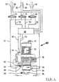
- 10 designates a suction unit, which aspirates and disassembles the mixture of air and liquid (cooling and rinsing water, saliva, blood, etc.) occurring at dental workplaces.
- the mixture is fed to the suction unit via a manifold 12, which can be connected via controllable 2/2 valves 14, 16, 18 to lines 20, 22, 24 leading to the individual workplaces.
- the air portion of the sucked-in mixture is provided by the suction unit 10 at an air outlet nozzle 26, which is usually connected to the roof of the building guided line is connected.
- the liquid components of the mixture are provided by the suction unit 10 at a liquid outlet connection 26, which is connected to the sewage system.
- the suction unit has an electric drive motor 30, on the underside of which a vacuum pump 32 is flanged to a known construction, which has, for example, an impeller seated on a pump shaft.
- a liquid separation cyclone denoted overall by 34, which in turn carries a discharge pump 36.
- the liquid separation cyclone 34 has an inlet connection 38 which takes over the mixture supplied from the collecting line 12 and an outlet connection 40 which provides the air freed from liquid and which is connected via a hose section 42 to one of the two inlets of a 3/2-way switch valve 44. Its second input is connected to the ambient atmosphere, its working opening is connected to the suction opening of the vacuum pump 32.
- the changeover valve 44 is controlled via a line 46 from a central control unit 48, which also supplies the drive motor 30 with energy via a line 50.
- the control unit 48 controls the operation of the valves 14, 16, 18 via additional lines 52, 54, 56, specifically as a function of control signals which are transferred from the individual workstations via lines 58, 60, 62 when suction is required there becomes.
- the control unit 48 is also connected to the output of a level sensor 64, which is carried by the peripheral wall of the liquid separation cyclone 34 and responds when the liquid level in the liquid separation cyclone 34 exceeds a predetermined, maximum permissible value, so that it is no longer guaranteed that the air emitted by the cyclone is completely free of liquid components. Under such conditions, the control unit 48 then switches the changeover valve 44 to the position in which air is drawn in from the ambient atmosphere, while the discharge pump 36 continues to be driven by the drive motor 30.
- control unit 48 brings the changeover valve 44 back into its normal position, in which the vacuum pump 32 is connected to the outlet port 40 of the liquid separation cyclone 34.
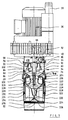
- FIG. 2 shows details of the internal structure of the suction unit 10.
- the shaft 66 of the drive motor 30, which also represents the pump shaft of the vacuum pump 32, is pulled through the liquid separating cyclone 34 and carries at its free end a pump impeller 68 of the discharge pump 36.
- the latter runs in one cup-shaped pump housing 70, which is screwed tightly onto the bottom of the housing of the liquid separation cyclone 34, designated 72.
- the cyclone housing 72 has a conically sloping bottom 74 which carries a central tubular transfer nozzle 76. Its diameter corresponds to the blade-free suction area of the pump impeller 68 and ends at a short axial distance above the latter.
- the pump impeller 68 injection molded from plastic has a raised hub section 78, via which it is clamped to the shaft 66 with the interposition of a propeller hub section 80 by means of a screw 82.
- the propeller hub section 80 belongs to a propeller, designated overall by 84, which also has a transverse one Disc section 86 and a plurality of circumferentially distributed propeller blades 88.
- the latter run in a downwardly open channel 90, which is delimited by a bell-shaped deflector section 92 and a tubular connector 94 coaxial therewith.
- the latter fixed parts of the cyclone housing 72 are formed on a bottom 96 of a cup-shaped housing head part 98, which delimits an outlet chamber 100 which is connected to the air outlet nozzle 40.
- the housing head part 98 is screwed tightly to the cyclone housing 72.
- the inlet connection 40 for the air / liquid mixture opens directly below the bottom 96 of the housing head part 98 into the peripheral wall of the cyclone housing 72 and is thus connected to the annular space 102, which is between the outside of the deflector section 92 and the peripheral wall of the cyclone housing 72 lies.
- the suction unit shown in Figure 2 works as follows:
- the drive motor 30 rotates the fan wheel of the vacuum pump 32, the propeller 84 and the pump impeller 68 together, since these parts are all seated on the shaft 66.
- Due to the negative pressure generated by the vacuum pump 32 the air / liquid mixture is drawn into the inlet connection 38 and, due to its eccentric introduction, passes through the interior of the liquid separation cyclone 34 on a helical path.
- the heavier liquid constituents are separated from the mixture by centrifugal force and flow under gravity through the conical cyclone bottom and the transfer nozzle 76 into the discharge pump 36.
- the separated liquid components of the mixture are pressed into the liquid outlet nozzle 28 by the pump impeller 68 thereof.
- the deflector section 92 prevents parts of the incoming air / liquid mixture from being able to get directly to the nozzle 94 and from there into the outlet chamber 100.
- Foam contained in the mixture supplied for example due to foam-forming constituents, likewise cannot get into the nozzle 94, since it must cross the propeller 84 in this way.
- the foam is broken up mechanically, and, moreover, it is set into very strong, rapid rotation by the propeller 84, so that a further liquid separation takes place by centrifugal force.
- This separation is also particularly effective because the propeller 84 rotates in a direction of rotation that is opposite to the direction of rotation of the helical path of the mixture through the liquid separation cyclone 34. From the inside of the cyclone housing, only air that has been completely freed of liquid constituents passes through the propeller 84 to the nozzle 94 and from there into the outlet chamber 100.
- the suction unit 10 has very compact dimensions and only three flow connections have to be made at the place of use, namely those to the collecting line 12, the one on the air outlet connector 26 and the one on the liquid outlet connector 28. Only a few connections need to be made for the electrical installation.
- the drive motor 30 is used for three different purposes: the generation of the negative pressure, the forced discharge of the separated liquid by the discharge pump 36 and the smashing and centrifuging of foam components of the sucked-in mixture by the propeller 84.
- pump vanes 104 which are placed on the upper end face of an annular upper blocking flange 106 of a centrifuge drum, generally designated 108, form a pump impeller for the forced discharge of the separated liquid.
- the centrifuge drum 108 has a cylindrical circumferential wall 110, at the upper end of which the locking flange 106 is attached, projecting radially inwards, and a conically sloping bottom 112, which is connected to a hub section 116 via a plurality of circumferential radial vanes 114. The latter is again clamped to the shaft 66 by means of the screw 82 with the interposition of the propeller 84.
- a central portion of the bottom 112 of the centrifuge drum 108 carries a conical, downwardly tapering transfer and return nozzle 118 which projects into a sedimentation chamber 120 which is located below the centrifuge drum 108 and in part through a cylindrical sedimentation housing 122 which is open at the bottom, partly by a collection bag 126 which is sealed at the bottom by a transverse weld 124.
- the latter is drawn tightly over the outer surface of the sedimentation housing 122, with a supply 128 of tubular bag material which has been zigzagged open is arranged in the interior of a cartridge 130 which is pushed tightly onto the outer surface of the sedimentation housing 122 and is axially fixed by means of clip springs 132.
- the sedimentation housing 122 is tightly connected to the pump housing 70, which is now open at the bottom.
- a plurality of calming vanes 134 lying in radial planes, which are formed on the inner wall of the sedimentation housing 122 in a distributed manner in the circumferential direction and end at a distance from the centrifuge drum 108.
- the calming vanes 134 are connected by a conical distribution section 136, which also forms an integrally molded part of the sedimentation housing 122 and is used for amalgam sludge, which, when the drive motor 30 is stopped by gravity, from the peripheral wall 110 of the centrifuge drum 108 via the bottom 112 thereof and the transfer and return pipe 118 sinks into the sedimentation chamber 120 to distribute in the circumferential direction.
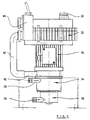
- FIGS. 3 and 4 operate similarly to the suction unit explained above with reference to FIGS. 1 and 2.
- the separated liquid constituents of the mixture supplied via the collecting line 12 are led into the interior of the centrifuge drum 108 by the nozzle 94, which is extended by a further nozzle part 138 which widens conically at the lower end to just above the upper edge of the vanes 114.
- the liquid is rapidly rotated by the vanes 114, and the entrained amalgam particles separate on the peripheral wall 110 under the action of the centrifugal force.
- Purified water flows into the pump housing 70 via the annular space, which is delimited by the inner edge of the blocking flange 106 and the outer surface of the connector 76, and is pumped through the pump vanes 104 into the Liquid outlet connector 28 pressed.
- the amalgam sludge retained in the centrifuge drum 108 sinks into the sedimentation chamber 120, as described above. There, the amalgam particles contained in the sludge settle under the influence of gravity, and a relatively clear liquid layer is obtained over the sediment thus formed, which is then pumped back into the inside of the centrifuge drum 108 by the transfer and return conveyor nozzle 118 when the drive motor 30 is in motion again is set.
- the collecting bag 126 If a predetermined amount of amalgam has deposited in the collecting bag 126, the collecting bag is pulled axially downward and closed by a further transverse welding seam at the upper end, for which purpose the suction unit has two welding bars 140 that can be moved perpendicular to the device axis, as shown in FIG. 4.
- Figure 5 shows a further modified embodiment, which is derived from the suction unit of Figures 1 and 2 in that the liquid separation cyclone 34 and the discharge pump 36 carried by it are placed on one end face of the drive motor 30, the internal structure of liquid separation cyclone 34 and Discharge pump 36 is exactly the same as shown in Figure 2.
- the motor shaft is also extended beyond the second end face of the motor housing and carries the impeller of the vacuum pump 32, which is now placed on the second end face of the drive motor 30 located in FIG. 5.
- suction unit according to FIG. 5 works the same as that shown in FIGS. 1 and 2.
- the suction unit shown in FIG. 6 parts which have already been described above with reference to FIG. 3 are again provided with the same reference symbols. These parts will not be described again in detail.
- the main difference of the suction unit according to FIG. 6 to that according to FIG. 3 is that the mixture of air, liquid and solid particles occurring at the workplace is supplied from below.
- the sedimentation housing 122 is designed as a fixed part and has a bottom 142 which delimits the sedimentation chamber 120 at the bottom.
- a central guide tube 144 stands up from this, which passes through the transfer / return nozzle 118 and is guided up to just above the bottom 112 of the centrifuge drum 108 .
- the interior of the guide tube 144 is connected to an outlet chamber 146 of a feed pump, designated overall by 148, which is placed on the lower end of the sedimentation housing 122.
- a feed pump designated overall by 148
- the pump housing and sedimentation housing 122 are shown in the drawing in one piece; it is understood that in practice they consist of several cup-shaped molded parts placed one against the other.
- the screw 82 now has an elongated head designed as a shaft 150.
- the shaft 150 extends through the guide tube 144 and traverses an upper end wall 152 of a pump chamber 154 in the sliding play. In the latter, a pump wheel 156 rotates, which is detachably fitted onto a slotted end section 158 of the shaft 150 is.
- the pump wheel 156 sucks the mixture occurring at the workplace through a central opening 160 of a lower end wall 162 of the pump chamber 154, which mixture is guided to an inlet connection 164 of the suction unit via a hose (not shown in more detail).
- a separating tube 166 is connected in a rotationally fixed manner to the centrifuge drum 108, which is similar in shape to the nozzle part 138 and has a lower separating tube section 168 which widens in a conical shape. Its free edge is at a greater distance from the drum axis than the inner edge of the locking flange 106.
- the separating tube 166 is connected to the hub section 116 of the centrifuge drum 108 via radial arms 170.
- the supplied air / liquid / solid particle mixture is conveyed from the feed pump 148 through the guide tube 144 into the lower end of the centrifuge drum 108.
- the mixture is rapidly rotated by vanes 114, the light air and foam components migrating towards the drum axis, while the heavy liquid components and solid particles migrate to the peripheral wall 110 of the centrifuge drum 108.
- the air separated in this way, together with fractions of foam, enters the interior of the separating tube 166, further strong centrifugation taking place because of the arms 170 carrying the separating tube 166. Liquid fractions formed in this way return via the conically widening separating tube section 168 back into the interior of the centrifuge drum 108.
Abstract
Description
Die Erfindung betrifft eine zahnärztliche Absaugeinrichtung gemäß dem Oberbegriff des Anspruches 1.The invention relates to a dental suction device according to the preamble of claim 1.
Bei derartigen bekannten Absaugeinrichtungen ist die Unterdruckpumpe über einen Schlauch mit einem räumlich von ihr getrennten Flüssigkeitsabscheidezyklon verbunden. Die im Zyklon abgetrennte Flüssigkeit wird über ein Schleusensystem an die Abwasserkanalisation abgegeben. Dies bedeutet, daß das Abgabeeende des Zyklons über der Abflußstelle der Abwasserkanalisation liegen muß. Für manche Anwendungen ist es jedoch vorteilhaft, wenn man bezüglich des Anbringungsortes des Zyklons oder einer anderen Luft/Flüssigkeits-Trenneinrichtung vollständig frei ist. Eine solche Freiheit könnte man z.B. dadurch gewinnen, daß man an die Flüssigkeitsaustragöffnung der Trenneinrichtung eine Flüssigkeitspumpe anschließt (s. EP-A 0 102 000), durch welche die abgetrennte Flüssigkeit zwangsweise auf ein höheres Niveau gefördert wird. Dies bedeutet aber zum einen einen deutlich erhöhten apparativen Aufwand für die Trenneinrichtung, darüber hinaus muß auch zur Trenneinrichtung hin eine Netzleitung geführt werden, an welche der Antriebsmotor der Flüssigkeitspumpe angeschlossen wird.In such known suction devices, the vacuum pump is connected via a hose to a liquid separation cyclone which is spatially separate from it. The liquid separated in the cyclone is released to the sewage system via a lock system. This means that the discharge end of the cyclone must be above the drainage point of the sewage system. For some applications, however, it is advantageous to be completely free as to the location of the cyclone or other air / liquid separator. Such freedom could e.g. win by connecting a liquid pump to the liquid discharge opening of the separating device (see EP-A 0 102 000), by means of which the separated liquid is forced to a higher level. On the one hand, however, this means a significantly increased outlay on equipment for the separating device; moreover, a power line must also be routed to the separating device, to which the drive motor of the liquid pump is connected.
Durch die vorliegende Erfindung soll daher eine zahnärztliche Absaugeinrichtung gemäß dem Oberbegriff des Anspruches 1 dahingehend weitergebildet werden, daß ein zwangsweises Austragen der in der Trenneinrichtung abgeschiedenen Flüssigkeit unter Überdruck erhalten wird, ohne daß ein zusätzlicher Antriebsmotor benötigt wird.The present invention is therefore intended to develop a dental suction device according to the preamble of claim 1 in such a way that a forced discharge of the liquid separated in the separating device is obtained under excess pressure without the need for an additional drive motor.
Diese Aufgabe ist erfindungsgemäß gelöst durch eine Absaugeinrichtung gemäß Anspruch 1.This object is achieved according to the invention by a suction device according to claim 1.
Bei der erfindungsgemäßen Absaugeinrichtung ist die Luft/Flüssigkeits-Trenneinrichtung mit der Unterdruckpumpe zu einer Einheit zusammengefaßt und der sowieso zum Bewegen des umlaufenden Pumpenelementes der Unterdruckpumpe vorgesehene Antriebsmotor dreht zugleich auch ein Pumpenlaufrad, welches die aus dem zugeführten Flüssigkeits-Luftgemisch abgeschiedene Flüssigkeit, welche sich am unteren Ende der Trenneinrichtung ansammelt, zwangsweise austrägt.In the suction device according to the invention, the air / liquid separating device is combined with the vacuum pump to form a unit and the drive motor provided anyway for moving the rotating pump element of the vacuum pump also rotates a pump impeller which removes the liquid separated from the supplied liquid-air mixture, which is on the accumulates lower end of the separator, forcibly discharges.
Die erfindungsgemäße Absaugeinrichtung läßt sich sowohl als zentrale Absaugeinrichtung für eine Mehrzahl von Arbeitsplätzen verwenden, wie im Anspruch 12 angegeben. Sie eignet sich aber auch gut zur dezentralen Installation direkt am Arbeitsplatz, wobei ihr kompakter Aufbau und die geringe Anzahl herzustellender Anschlüsse von Vorteil sind.The suction device according to the invention can be used both as a central suction device for a plurality of workplaces, as specified in
Vorteilhafte Weiterbildungen der Erfindung sind in Unteransprüchen angegeben.Advantageous developments of the invention are specified in the subclaims.
Die Weiterbildungen der Erfindungen gemäß den Ansprüchen 3 und 4 sind im Hinblick auf möglichst geringe radiale Abmessungen der Ansaugeinheit von Vorteil. Durch die angegebene Anordnung der Trenneinrichtung ist darüber hinaus die erforderliche Höhenbeziehung zwischen der Trenneinrichtung und der Austrageinrichtung zwangsläufig gewährleistet.The developments of the inventions according to claims 3 and 4 are advantageous with regard to the smallest possible radial dimensions of the suction unit. The specified arrangement of the separating device also necessarily ensures the required height relationship between the separating device and the discharge device.
Bei einer Absaugeinrichtung gemäß Anspruch 4 sind darüber hinaus die fliegend gelagerten Wellenabschnitte nur kurz, und die Unterdruckpumpe hat großen axialen Abstand von der Trenneinrichtung, so daß auch bei kurzfristiger Überbeschickung der Trenneinrichtung dann etwa in die Luftaustrittsöffnung derselben gelangende Flüssigkeitsanteile nicht direkt in die Unterdruckpumpe gelangen.In a suction device according to claim 4, the overhung shaft sections are also only short, and the vacuum pump is at a large axial distance from the separating device, so that even if the separating device is briefly overcharged, any liquid that gets into the air outlet opening of the separating device does not get directly into the vacuum pump.
Mit der Weiterbildung der Erfindung gemäß Anspruch 5 wird erreicht, daß stabile Schaumanteile, welche sich im angesaugten Luft/Flüssigkeitsgemisch befinden, mechanisch zerschlagen werden und so nicht in die Luftaustrittsöffnung der Trenneinrichtung gelangen.With the development of the invention according to claim 5 ensures that stable fractions of foam, which are in the sucked-in air / liquid mixture, are mechanically smashed and thus do not get into the air outlet opening of the separating device.
Die Weiterbildungen der Erfindung gemäß den Ansprüchen 6 und 7 sind im Hinblick auf das Zuführen der in der Trenneinrichtung abgetrennten Flüssigkeitsanteile zum Pumpenlaufrad vorteilhaft.The developments of the invention according to claims 6 and 7 are advantageous with regard to the supply of the liquid components separated in the separating device to the pump impeller.
Bei einer Absaugeinrichtung, wie sie im Anspruch 8 angegeben ist, können unter Verwendung des beim Stand der Technik nur zum Betreiben der Unterdruckpumpe dienenden Antriebsmotors auch Feststoffpartikel wie Amalgampartikel aus den aus dem ursprünglichen Gemisch abgetrennten Flüssigkeitsanteilen abgeschieden werden, so daß sie nicht in die Abwasserkanalisation gelangen.In a suction device as specified in claim 8, solid particles such as amalgam particles can also be separated from the liquid components separated from the original mixture using the drive motor used in the prior art only for operating the vacuum pump, so that they do not get into the sewage system .
Mit der Weiterbildung der Erfindung gemäß Anspruch 9 wird erreicht, daß sich der im Inneren der Zentrifugentrommel ansammelnde Schlamm aus Feststoffpartikeln jeweils beim Anhalten der Einrichtung unter Schwerkrafteinwirkung in den unter der Zentrifugentrommel liegenden Sedimentierbehälter bewegt, wo sich dann über einem Sediment aus Feststoffpartikeln ein geklärtes Flüssigkeitsvolumen ansammelt, welches beim Wiederanschalten der Einrichtung durch den vom Boden der Zentrifugentrommel getragenen Übergabe- und Rückpumpstutzen wieder ins Innere der Zentrifuge zurückgepumpt wird.With the development of the invention according to claim 9, it is achieved that the sludge of solid particles accumulating inside the centrifuge drum moves under the influence of gravity into the sedimentation container under the centrifuge drum, where a clarified volume of liquid then accumulates over a sediment of solid particles , which is pumped back into the interior of the centrifuge when the device is switched on again by the transfer and return pump nozzle carried by the bottom of the centrifuge drum.
Mit der Weiterbildung der Erfindung gemäß Anspruch 10 wird erreicht, daß die Austragpumpe und gegebenenfalls die Zentrifuge zum Abscheiden von Feststoffpartikeln auch dann weiterlaufen, wenn die Einlaßöffnung der gesamten Ansaugeinheit vorübergehend nicht mit Unterdruck beaufschlagt werden darf, um keine weiteren Gemischmengen anzusaugen, da die Kapazität der Trenneinrichtung z.B. aufgrund von Schwallwasserzuführung vorübergehend überschritten ist. Unter solchen Betriebsbedingungen wird über das Umschaltventil vorübergehend Luft aus der Umgebung von der Unterdruckpumpe angesaugt.With the development of the invention according to
Gemäß Anspruch 11 erfolgt die Steuerung des dem Einlaß der Unterdruckpumpe vorgeschalteten Umschaltventiles unter Verwendung des Ausgangssignales eines Flüssigkeits-Pegelfühlers, der bei Überschreiten eines vorgegebenen Flüssigkeitsniveaus in der Trenneinrichtung anspricht.According to claim 11, the control of the switching valve upstream of the inlet of the vacuum pump is carried out using the output signal of a liquid level sensor which responds when a predetermined liquid level in the separating device is exceeded.
Mit der Weiterbildung der Erfindung gemäß Anspruch 14 wird erreicht, daß auch in der Zentrifugentrommel eine Trennung von Luft und Flüssigkeit durchgeführt wird. Dieser Trenneffekt kann zusätzlich zu demjenigen erhalten werden, den ein etwa ebenfalls zur Absaugeinrichtung gehörender Flüssigkeitsabscheidezyklon gewährleistet; in manchen Anwendungsfällen läßt sich sogar auf einen derartigen Zyklon vollständig verzichten, wenn die Trenneinrichtung gemäß Anspruch 14 ausgebildet ist.With the development of the invention according to
Die Weiterbildung der Erfindung gemäß Anspruch 15 ist im Hinblick auf eine verbesserte Trennung von Luft und Flüssigkeit durch das Trennrohr von Vorteil.The development of the invention according to claim 15 is advantageous with regard to an improved separation of air and liquid through the separation tube.
Mit der Weiterbildung der Erfindung gemäß Anspruch 16 wird erreicht, daß die vom Trennrohr abgeschiedene Flüssigkeitsmenge hinter die Innenfläche des sich in der Zentrifugentrommel ausbildenden Wasserringes geführt wird. Diese Flüssigkeitsmenge wird somit in der Zentrifugentrommel intensiv zentrifugiert und kann nicht direkt über die Innenfläche des Wasserringes zum Sperrflansch der Zentrifugentrommel gelangen.With the development of the invention according to
Nachstehend wird die Erfindung anhand von Ausführungsbeispielen unter Bezugnahme auf die Zeichnung näher erläutert. In dieser zeigen:
- Figur 1: eine schematische Ansicht einer zentralen Absauganlage für drei zahnärztliche Arbeitsplätze;
- Figur 2: einen axialen Teilschnitt durch die Absaugeinheit der in Figur 1 gezeigten Anlage;
- Figur 3: eine ähnliche Schnittansicht wie Figur 2, in welcher jedoch eine Absaugeinheit mit integrierter Amalgamabscheidung gezeigt ist;
- Figur 4: eine um 90 Grad versetzte seitliche Ansicht der Absaugeinheit nach Figur 3;
- Figur 5: eine seitliche Ansicht einer weiter abgewandelten Absaugeinheit; und
- Figur 6: einen ähnlichen Schnitt wie Figur 3 durch eine weiter abgewandelte Absaugeinheit.
- Figure 1 is a schematic view of a central suction system for three dental workplaces;
- FIG. 2: an axial partial section through the suction unit of the system shown in FIG. 1;
- Figure 3: a similar sectional view as Figure 2, but in which a suction unit with integrated amalgam deposition is shown;
- FIG. 4: a side view of the suction unit according to FIG. 3, offset by 90 degrees;
- Figure 5: a side view of a further modified suction unit; and
- Figure 6: a similar section as Figure 3 through a further modified suction unit.
In Figur 1 ist mit 10 insgesamt eine Absaugeinheit bezeichnet, welche das an zahnärztlichen Arbeitsplätzen anfallende Gemisch aus Luft und Flüssigkeit (Kühl- und Spülwasser, Speichel, Blut usw.) absaugt und zerlegt. Das Gemisch wird der Absaugeinheit über eine Sammelleitung 12 zugeführt, die über steuerbare 2/2-Ventile 14, 16, 18 mit zu den einzelnen Arbeitsplätzen führenden Leitungen 20, 22, 24 verbindbar ist. Der Luftanteil des angesaugten Gemisches wird von der Ansaugeinheit 10 an einem Luftauslaßstutzen 26 bereitgestellt, der mit einer in der Regel über das Gebäudedach geführten Leitung verbunden ist. Die Flüssigkeitsanteile des Gemisches werden von der Absaugeinheit 10 an einem Flüssigkeitsauslaßstutzen 26 bereitgestellt, der mit der Abwasserkanalisation verbunden ist.In Figure 1, 10 designates a suction unit, which aspirates and disassembles the mixture of air and liquid (cooling and rinsing water, saliva, blood, etc.) occurring at dental workplaces. The mixture is fed to the suction unit via a
Die Absaugeinheit weist einen elektrischen Antriebsmotor 30 auf, an dessen Unterseite eine Unterdruckpumpe 32 an sich bekannten Aufbaus angeflanscht ist, die beispielsweise ein auf einer Pumpenwelle sitzendes Gebläserad aufweist. An der Unterseite der Unterdruckpumpe 32 hängt ein insgesamt mit 34 bezeichneter Flüssigkeitsabscheidezyklon, der wiederum eine Austragpumpe 36 trägt.The suction unit has an
Der Flüssigkeitsabscheidezyklon 34 hat einen das von der Sammelleitung 12 zugeführte Gemisch übernehmenden Eintrittsstutzen 38 und einen die von Flüssigkeit befreite Luft bereitstellenden Austrittstutzen 40, der über ein Schlauchstück 42 mit einem der beiden Einlässe eines 3/2-Umschaltventiles 44 verbunden ist. Dessen zweiter Eingang steht mit der Umgebungsatmosphäre in Verbindung, seine Arbeitsöffnung ist mit der Ansaugöffnung der Unterdruckpumpe 32 verbunden.The
Die Steuerung des Umschaltventiles 44 erfolgt über eine Leitung 46 von einer zentralen Steuereinheit 48 her, welche über eine Leitung 50 auch den Antriebsmotor 30 mit Energie versorgt.The
Die Steuereinheit 48 steuert über weitere Leitungen 52, 54, 56 das Arbeiten der Ventile 14, 16, 18, und zwar in Abhängigkeit von Steuersignalen, die über Leitungen 58, 60, 62 von den einzelnen Arbeitsplätzen dann überstellt werden, wenn dort ein Absaugen benötigt wird. Die Steuereinheit 48 ist ferner mit dem Ausgang eines Pegelfühlers 64 verbunden, der von der Umfangswand des Flüssigkeitsabscheidezyklons 34 getragen ist und dann anspricht, wenn der Flüssigkeitsspiegel im Flüssigkeitsabscheidezyklon 34 einen vorgegebenen, maximal zulässigen Wert überschreitet, so daß nicht mehr gewährleistet ist, daß die vom Zyklon abgegebene Luft völlig frei von flüssigen Bestandteilen ist. Unter derartigen Bedingungen schaltet die Steuereinheit 48 das Umschaltventil 44 dann in diejenige Stellung, in welcher Luft aus der Umgebungsatmosphäre angesaugt wird, während die Austragpumpe 36 weiterhin vom Antriebsmotor 30 angetrieben wird. Ist der Flüssigkeitsspiegel im Inneren des Flüssigkeitsabscheidezyklons 34 wieder unter den maximal zulässigen Pegel abgefallen, so bringt die Steuereinheit 48 das Umschaltventil 44 wieder in seine Normalstellung, in welcher die Unterdruckpumpe 32 mit dem Austrittstutzen 40 des Flüssigkeitsabscheidezyklons 34 verbunden ist.The
Figur 2 zeigt Einzelheiten des inneren Aufbaus der Absaugeinheit 10. Die Welle 66 des Antriebsmotors 30, welche zugleich die Pumpenwelle der Unterdruckpumpe 32 darstellt, ist durch den Flüssigkeitsabscheidezyklon 34 hindurchgezogen und trägt an ihrem freien Ende ein Pumpenlaufrad 68 der Austragpumpe 36. Letzteres läuft in einem becherförmigen Pumpengehäuse 70, welches dicht auf den Boden des mit 72 bezeichneten Gehäuses des Flüssigkeitsabscheidezyklons 34 aufgeschraubt ist.Figure 2 shows details of the internal structure of the
Wie Figur 2 zeigt, hat das Zyklongehäuse 72 einen kegelförmig abfallenden Boden 74, der einen mittigen rohrförmigen Übergabestutzen 76 trägt. Dessen Duchmesser entspricht dem schaufelfreien Ansaugbereich des Pumpenlaufrades 68 und endet unter kurzem axialem Abstand über letzterem. Das aus Kunststoff gespritzte Pumpenlaufrad 68 hat einen hochgezogenen Nabenabschnitt 78, über welchen es unter Zwischenschalten eines Propellernabenabschnittes 80 mittels einer Schraube 82 mit der Welle 66 verspannt ist.As FIG. 2 shows, the
Der Propellernabenabschnitt 80 gehört zu einem insgesamt mit 84 bezeichneten Propeller, der ferner einen transversalen Scheibenabschnitt 86 und eine Mehrzahl in Umfangsrichtung verteilter Propellerflügel 88 aufweist. Letztere laufen in einer nach unten offenen Rinne 90, welche durch einen glockenförmigen Deflektorabschnitt 92 und einen hierzu koaxialen rohrförmigen Stutzen 94 begrenzt ist. Die letztgenannten feststehenden Teile des Zyklongehäuses 72 sind an einen Boden 96 eines becherförmigen Gehäusekopfteiles 98 angeformt, welches eine mit dem Luftaustrittsstutzen 40 in Verbindung stehende Austrittskammer 100 begrenzt. Das Gehäusekopfteil 98 ist dicht mit dem Zyklongehäuse 72 verschraubt.The
Wie Figur 2 zeigt, mündet der Eintrittstutzen 40 für das Luft/Flüssigkeitsgemisch unmittelbar unterhalb des Bodens 96 des Gehäusekopfteiles 98 in die Umfangswand des Zyklongehäuses 72 und steht somit mit dem Ringraum 102 in Verbindung, welcher zwischen der Aussenseite des Deflektorabschnittes 92 und der Umfangswand des Zyklongehäuses 72 liegt.As FIG. 2 shows, the
Die in Figur 2 gezeigte Absaugeinheit arbeitet folgendermaßen:
Der Antriebsmotor 30 dreht das Gebläserad der Unterdruckpumpe 32, den Propeller 84 und das Pumpenlaufrad 68 gemeinsam, da diese Teile alle auf der Welle 66 sitzen. Auf Grund des von der Unterdruckpumpe 32 erzeugten Unterdruckes wird das Luft/Flüssigkeitsgemisch in den Eintrittstutzen 38 gezogen und durchläuft auf Grund seiner außermittigen Einleitung das Innere des Flüssigkeitsabscheidezyklons 34 auf einer wendelförmigen Bahn. Durch Zentrifugalkraft werden bei dieser Bewegung die schwereren Flüssigkeitsbestandteile aus dem Gemisch abgetrennt und fliessen unter Schwerkrafteinwirkung über den kegelfömigen Zyklonboden und den Übergabestutzen 76 in die Austragpumpe 36. Von deren Pumpenlaufrad 68 werden die abgetrennten flüssigen Bestandteile des Gemisches in den Flüssigkeitsauslaßstutzen 28 gedrückt.The suction unit shown in Figure 2 works as follows:
The
Der Deflektorabschnitt 92 verhindert, daß Teile des eintretenden Luft/Flüssigkeitsgemisches direkt zu dem Stutzen 94 und von dort in die Austrittskammer 100 gelangen können.The
Etwa auf Grund schaumbildender Bestandteile im zugeführten Gemisch enthaltener Schaum kann ebenfalls nicht in den Stutzen 94 gelangen, da er auf diesem Wege den Propeller 84 durchqueren muß. Hierbei wird der Schaum zum einen mechanisch zerschlagen, darüber hinaus wird er durch den Propeller 84 auch in sehr starke, rasche Drehung versetzt, sodaß eine weitere Flüssigkeitsabscheidung durch Zentrifugalkraft erfolgt. Diese Abscheidung ist auch deshalb besonders effektiv, da der Propeller 84 in einem Drehsinne umläuft, der der Drehrichtung des wendelförmigen Weges des Gemisches durch den Flüssigkeitsabscheidezyklon 34 entgegengesetzt ist. Aus dem Inneren des Zyklongehäuses gelangt somit nur vollständig von flüssigen Bestandteilen befreite Luft durch den Propeller 84 hindurch zum Stutzen 94 und von dort in die Austrittskammer 100.Foam contained in the mixture supplied, for example due to foam-forming constituents, likewise cannot get into the
Man erkennt, daß die Absaugeinheit 10 sehr kompakte Abmessungen aufweist und am Einsatzort nur drei Stömungsverbindungen herzustellen sind, nämlich die zur Sammelleitung 12, die am Luftauslaßstutzen 26 und die am Flüssigkeitsauslaßstutzen 28. Auch für die elektrische Installation brauchen nur wenige Verbindungen hergestellt zu werden.It can be seen that the
Man erkennt ferner, daß bei der oben beschriebenen Absaugeinheit der Antriebsmotor 30 für drei verschiedene Zwecke genutzt wird: die Erzeugung des Unterdruckes, das zwangsweise Austragen der abgeschiedenen Flüssigkeit durch die Austragpumpe 36 und das Zerschlagen und Zentrifugieren von Schaumbestandteilen des angesaugten Gemisches durch den Propeller 84.It can also be seen that in the suction unit described above, the
Bei dem in Figur 3 gezeigten abgewandelten Ausführungsbeispiel sind Bauteile der Absaugeinheit 10, welche obenstehend unter Bezugnahme auf die Figuren 1 und 2 schon erläutert wurden, wieder mit demselben Bezugszeichen versehen. Diese Bauteile werden nicht noch einmal im einzelnen beschrieben. Der Hauptunterschied des in Figur 3 und 4 gezeigten Ausführungsbeispieles zum Ausführungsbeispiel nach den Figuren 1 und 2 besteht darin, daß das Pumpenlaufrad als Teil einer Überlaufzentrifugentrommel ausgebildet ist, welche zum Abscheiden von Amalgampartikeln aus der aus dem Gemisch abgetrennten Flüssigkeit dient.In the modified embodiment shown in Figure 3 Components of the
Bei der Absaugeinheit nach Figur 3 bilden Pumpenflügel 104, die auf die obere Stirnfläche eines ringförmigen oberen Sperrflansches 106 einer insgesamt mit 108 bezeichneten Zentrifugentrommel aufgesetzt sind, ein Pumpenlaufrad zum zwangsweisen Austragen der abgeschiedenen Flüssigkeit.In the suction unit according to FIG. 3,
Die Zentrifugentrommel 108 hat eine zylindrische Umfangswand 110, an deren oberem Ende der Sperrflansch 106 radial nach innen ragend angebracht ist, sowie einen kegelförmig abfallenden Boden 112, der über mehrere in Umfangsrichtung verteilte radiale Flügel 114 mit einem Nabenabschnitt 116 verbunden ist. Letzterer ist wieder mittels der Schraube 82 unter Zwischenschaltung des Propellers 84 mit der Welle 66 verspannt.The
Ein mittiger Abschnitt des Bodens 112 der Zentrifugentrommel 108 trägt einen kegelförmigen, sich nach unten verjüngenden Übergabe- und Rückförderstutzen 118, der in eine Sedimentierkammer 120 hineinragt, die sich unterhalb der Zentrifugentrommel 108 befindet und zum Teil durch ein zylindrisches, nach unten offenes Sedimentiergehäuse 122, zum Teil durch einen unten durch eine transversale Schweißnaht 124 dicht verschlossenen Sammelbeutel 126 dicht begrenzt ist. Letzterer ist dicht über die Aussenfläche des Sedimentiergehäuses 122 gezogen, wobei ein zickzackförmig aufgeschossener Vorrat 128 an schlauchförmigem Beutelmaterial im Inneren einer Kartusche 130 angeordnet ist, die dicht auf die Aussenfläche des Sedimentiergehäuses 122 aufgeschoben ist und über Bügelfedern 132 axial festgelegt ist. Das Sedimentiergehäuse 122 ist dicht mit dem nun nach unten offen ausgebildeten Pumpengehäuse 70 verbunden.A central portion of the bottom 112 of the
Im Inneren der Sedimentierkammer 120 ist eine Mehrzahl in radialen Ebenen liegender Beruhigungsflügel 134 vorgesehen, die in Umfangsrichtung verteilt an die Innenwand des Sedimentiergehäuses 122 angeformt sind und unter Abstand vor der Zentrifugentrommel 108 enden. An ihrem unteren Ende sind die Beruhigungsflügel 134 durch einen kegelfömigen Verteilabschnitt 136 verbunden, der ebenfalls einen einstückig gespritzten Teil des Sedimentiergehäuses 122 darstellt und dazu dient, Amalgamschlamm, der beim Anhalten des Antriebsmotors 30 unter Schwerkrafteinwirkung von der Umfangswand 110 der Zentrifugentrommel 108 über deren Boden 112 und den Übergabe- und Rückförderstutzen 118 in die Sedimentierkammer 120 absinkt, in Umfangsrichtung zu verteilen.Provided in the interior of the
Die in Figur 3 und 4 gezeigte Absaugeinheit arbeitet in ihren Grundzügen ähnlich wie die obenstehend unter Bezugnahme auf die Figuren 1 und 2 erläuterte Absaugeinheit. Die abgetrennten flüssigen Bestandteile des über die Sammelleitung 12 zugeführten Gemisches werden jedoch vom Stutzen 94, der durch ein weiteres, sich am unteren Ende kegelförmig erweiterndes Stutzenteil 138 bis unmittelbar über die Oberkante der Flügel 114 verlängert ist, ins Innere der Zentrifugentrommel 108 geleitet. Dort wird die Flüssigkeit durch die Flügel 114 rasch in Drehung versetzt, und unter der Einwirkung der Zentrifugalkraft scheiden sich die mitgeschleppten Amalgampartikel auf der Umfangswand 110 ab. Gereinigtes Wasser strömt über den ringförmigen Zwischenraum, der durch die Innenkante des Sperrflansches 106 und die Aussenfläche des Stutzens 76 begrenzt ist, in das Pumpengehäuse 70 und wird durch die Pumpenflügel 104 in den Flüssigkeitsauslaßstutzen 28 gedrückt.The basic principles of the suction unit shown in FIGS. 3 and 4 operate similarly to the suction unit explained above with reference to FIGS. 1 and 2. However, the separated liquid constituents of the mixture supplied via the collecting
Wird der Antriebsmotor 30 nach Beendigung der Arbeitszeit abgeschaltet, so sinkt der in der Zentrifugentrommel 108 zurückgehaltene Amalgamschlamm in die Sedimentierkammer 120 ab, wie oben beschrieben. Dort setzen sich die im Schlamm enthaltenen Amalgampartikel unter Schwerkrafteinwirkung ab, und man erhält über dem so entstehenden Sediment eine verhältnismäßig klare Flüssigkeitsschicht, die von dem Übergabe- und Rückförderstutzen 118 dann wieder ins Innere der Zentrifugentrommel 108 zurückgepumpt wird, wenn der Antriebsmotor 30 wieder in Gang gesetzt wird.If the
Hat sich im Sammelbeutel 126 eine vorgegebene Amalgammenge abgeschieden, so wird der Sammelbeutel axial nach unten weggezogen und durch eine weitere transversale Schweissnaht am oberen Ende verschlossen, wozu die Absaugeinheit zwei senkrecht zur Geräteachse bewegbare Schweissbalken 140 aufweist, wie in Figur 4 gezeigt.If a predetermined amount of amalgam has deposited in the collecting
Figur 5 zeigt ein weiter abgewandeltes Ausführungsbeispiel, welches aus der Absaugeinheit nach Figur 1 und 2 dadurch abgeleitet ist, daß der Flüssigkeitsabscheidezyklon 34 und die von ihm getragene Austragpumpe 36 auf die eine Stirnfläche des Antriebsmotors 30 aufgesetzt sind, wobei der innere Aufbau von Flüssigkeitsabscheidezyklon 34 und Austragpumpe 36 genau gleich ist wie in Figur 2 gezeigt.Figure 5 shows a further modified embodiment, which is derived from the suction unit of Figures 1 and 2 in that the
Bei dem in Figur 5 gezeigten Ausführungsbeispiel ist aber die Motorwelle auch über die zweite Stirnfläche des Motorgehäuses hinausgezogen und trägt das Gebläserad der Unterdruckpumpe 32, die nunmehr auf die in Figure 5 obenliegende zweite Stirnfläche des Antriebsmotors 30 aufgesetzt ist.In the exemplary embodiment shown in FIG. 5, however, the motor shaft is also extended beyond the second end face of the motor housing and carries the impeller of the
Auf diese Weise erhält man einen grösseren axialen, vertikalen Abstand zwischen der Unterdruckpumpe 32 und dem Flüssigkeitsabscheidezyklon 34, so daß auch bei Beaufschlagung des Flüssigkeitsabscheidezyklons 34 mit größeren Schwallwassermengen keine Flüssigkeit in die Unterdruckpumpe 32 gelangt; das nun längere Schlauchstück 42 dient als zusätzlich zur Verfügung stehende Pufferstrecke.In this way, a larger axial, vertical distance between the
Im übrigen arbeitet die Absaugeinheit nach Figur 5 gleich wie die in Figur 1 und 2 gezeigte.Otherwise, the suction unit according to FIG. 5 works the same as that shown in FIGS. 1 and 2.
Bei der in Figur 6 gezeigten Absaugeinheit sind Teile, die obenstehend unter Bezugnahme auf Figur 3 schon beschrieben wurden, wieder mit denselben Bezugszeichen versehen. Diese Teile werden nicht noch einmal detailliert beschrieben. Der Hauptunterschied der Absaugeinheit nach Figur 6 zu derjenigen nach Figur 3 liegt darin, daß die Zufuhr des am Arbeitsplatz anfallenden Gemisches aus Luft, Flüssigkeit und Feststoffpartikeln von unten her erfolgt. Das Sedimentiergehäuse 122 ist als festes Teil ausgebildet und hat einen die Sedimentierkammer 120 unten begrenzenden Boden 142. Von diesem steht ein zentrales Leitrohr 144 nach oben, welches durch den Übergabe-/Rückförderstutzen 118 durchsetzt und bis kurz über den Boden 112 der Zentrifugentrommel 108 geführt ist. Das Innere des Leitrohres 144 steht mit einer Auslaßkammer 146 einer insgesamt mit 148 bezeichneten Speisepumpe in Verbindung, die auf das untere Ende des Sedimentiergehäuses 122 aufgesetzt ist. Der Einfachheit halber sind in der Zeichnung Pumpengehäuse und Sedimentiergehäuse 122 also einstückiges Teil wiedergegeben; es versteht sich, daß sie in der Praxis aus mehreren aneinandergesetzten becherförmigen Spritzteilen bestehen. Die Schraube 82 hat nunmehr einen als Welle 150 ausgebildeten gestreckten Kopf. Die Welle 150 erstreckt sich durch das Leitrohr 144 hindurch und durchquert im Gleitspiel eine obere Stirnwand 152 einer Pumpenkammer 154. In letzterer läuft ein Pumpenrad 156 um, welches auf einen geschlitzten Endabschnitt 158 der Welle 150 lösbar im Schnappsitz aufgesetzt ist. Das Pumpenrad 156 saugt über eine mittige Öffnung 160 einer unteren Stirnwand 162 der Pumpenkammer 154 das am Arbeitsplatz anfallende Gemisch an, welches über einen nicht näher gezeigten Schlauch zu einem Einlaßstutzen 164 der Absaugeinheit geführt wird.In the suction unit shown in FIG. 6, parts which have already been described above with reference to FIG. 3 are again provided with the same reference symbols. These parts will not be described again in detail. The main difference of the suction unit according to FIG. 6 to that according to FIG. 3 is that the mixture of air, liquid and solid particles occurring at the workplace is supplied from below. The
Mit der Zentrifugentrommel 108 ist ein Trennrohr 166 drehfest verbunden, welches von der Form her dem Stutzenteil 138 ähnelt und einen sich kegelförmig erweiternden unteren Trennrohrabschnitt 168 hat. Dessen freie Randkante hat größeren Abstand von der Trommelachse als der innere Rand des Sperrflansches 106. Das Trennrohr 166 ist über radiale Arme 170 mit dem Nabenabschnitt 116 der Zentrifugentrommel 108 verbunden.A separating
Bei der in Figur 6 gezeigten Absaugeinheit wird das zugeführte Luft-/Flüssigkeits-/Feststoffpartikel-Gemisch von der Speisepumpe 148 durch das Leitrohr 144 in das untere Ende der Zentrifugentrommel 108 gefördert. Hier wird das Gemisch durch die Flügel 114 in rasche Drehung versetzt, wobei die leichten Luftbestandteile und Schaumbestandteile zur Trommelachse hin wandern, während die schweren Flüssigkeitsbestandteile und die Feststoffpartikel zur Umfangswand 110 der Zentrifugentrommel 108 wandern. Die so abgetrennte Luft tritt zusammen mit Schaumanteilen in das Innere des Trennrohres 166 ein, wobei wegen der das Trennrohr 166 tragenden Arme 170 ein weiteres starkes Zentrifugieren erfolgt. Hierbei gebildete Flüssigkeitsanteile gelangen über den sich kegelförmig erweiternden Trennrohrabschnitt 168 wieder zurück ins Innere der Zentrifugentrommel 108.In the suction unit shown in FIG. 6, the supplied air / liquid / solid particle mixture is conveyed from the
Die Luftanteile und etwaige Schaum-Restanteile werden vom oberen Ende des Trennrohres 166 ins Innere des Zyklons 34 abgegeben, wo eine weitere Flüssigkeitsabscheidung stattfindet. Letzteres zum einen durch den Drall der Luftbewegung, zum anderen unter der Einwirkung des Propellers 84. Es gelangt somit nur von Flüssigkeitsanteilen befreite Luft in den Austrittsstutzen 40.The air fractions and any residual foam fractions are discharged from the upper end of the separating
Claims (16)
- Dental aspirator, with a suction pump (32) comprising a rotating pump member, with a drive motor (30) acting on the pump shaft, with a device (34) preceding the inlet opening of the suction pump, for separating liquid from the air/liquid mixture supplied to the aspirator, the inlet port of the suction pump (32) communicating with the air outlet port of the air/liquid separating device, and with a delivery pump (36) for the separated liquid comprising a pump impeller (68; 104, 106) rotating in a delivery pump casing (70), characterised in that a section of the drive shaft (66) supports the pump impeller (68; 104, 106) of the delivery pump (36) and that the air/liquid separating device (34), the suction pump (32) and the delivery pump (36) are combined as one unit.
- Aspirator according to Claim 1, characterised in that the air/liquid separating device comprises a liquid separating cyclone (34), which is provided at axially spaced points of its housing with an inlet opening for the air/liquid mixture and an outlet opening for air from which liquid has been removed and in its lower section comprises a liquid discharge opening (76); and that the liquid discharge opening (76) of the liquid separating cyclone (34) lies above the inlet opening of the delivery pump (36) and is connected to the latter so that the liquid separated from the mixture in the liquid separating cyclone (34) flows under the action of gravity into the delivery pump (36).
- Aspirator according to Claim 2, characterised in that the liquid discharge opening (76) of the liquid separating cyclone (34) is located in a central section of the base (74) of the cyclone casing and the liquid separating cyclone (34) is fitted in a tight manner to the pump casing (70) coaxial to the pump impeller (68; 104, 106) and in turn supports the suction pump (32).
- Aspirator according to one of Claims 1 to 3, characterised in that the air/liquid separating device (34) is fitted coaxially to one end face of the drive motor (30) and in turn supports the delivery pump (36) likewise coaxially, whereas the suction pump (32) is fitted coaxially to the second end face of the drive motor (30).
- Aspirator according to one of Claims 1 to 4, characterised in that the drive shaft (66) supporting the pump impeller extends in an upper section of a housing (72) of the separating device (34) and at this point supports a propeller (84), which is provided with blades (88), which pass with clearance between an air outlet connection (94) and a deflector part (92) surrounding the latter coaxially at a distance.
- Aspirator according to one of Claims 1 to 5, characterised in that the base (74) of the housing (72) of the air/liquid separating device slopes downwards towards the centre of the base.
- Aspirator according to Claim 6, characterised in that the base (74) of the housing (72) of the air/liquid separating device supports a central connection (76), which terminates a short distance above the suction section of the pump impeller (68).
- Aspirator according to one of Claims 1 to 7, characterised in that the pump impeller is formed by an upper blocking flange (106) and pump vanes (104) of a centrifuge drum (108) fitted thereon, which centrifuge drum (108) is fitted on the drive shaft (66).
- Aspirator according to Claim 8, characterised in that located below the centrifuge drum (108) is a sedimentation chamber (120), to which the inside of the centrifuge drum (108) is connected by way of a transfer and return connection (118) supported by the drum base (112).
- Aspirator according to one of Claims 1 to 9, characterised by a controllable change-over valve (44), by which the suction opening of the suction pump (32) can be connected optionally to the atmosphere instead of to the air outlet opening (40) of the air/liquid separating device (34).
- Aspirator according to Claim 10, characterised by a liquid level sensor (64) associated with the air/liquid separating device (34), the output signal of which sensor controls the change-over valve (44).
- Aspirator according to one of Claims 1 to 11, characterised in that the mixture inlet opening (38) of the air/liquid separating device (34) is connected to a collecting line (12), to which a plurality of working position lines (20 to 24) is connected.
- Aspirator according to Claim 12, characterised in that the working position lines (20 to 24) can each be connected by way of a controllable separating valve (14 to 18) to the collecting line (12).
- Aspirator according to one of Claims 8 to 13, characterised in that the separating device comprises a separating column (166) rotating with the centrifuge drum (108) and coaxial to the drum axis, which is guided with radial clearance through the blocking flange (106) of the centrifuge drum (108).
- Aspirator according to Claim 14, characterised in that a lower separating column section (168) widens out conically.
- Aspirator according to Claim 15, characterised in that the edge of the lower separating column section (168) is at a greater distance from the drum axis than the inner edge of the blocking flange (106).
Priority Applications (1)
| Application Number | Priority Date | Filing Date | Title |
|---|---|---|---|
| AT87100374T ATE55690T1 (en) | 1986-01-17 | 1987-01-14 | DENTAL SUCTION DEVICE. |
Applications Claiming Priority (2)
| Application Number | Priority Date | Filing Date | Title |
|---|---|---|---|
| DE3601254A DE3601254C2 (en) | 1986-01-17 | 1986-01-17 | Dental suction device |
| DE3601254 | 1986-01-17 |
Publications (3)
| Publication Number | Publication Date |
|---|---|
| EP0237708A1 EP0237708A1 (en) | 1987-09-23 |
| EP0237708B1 EP0237708B1 (en) | 1990-08-22 |
| EP0237708B2 true EP0237708B2 (en) | 1996-03-13 |
Family
ID=6292048
Family Applications (1)
| Application Number | Title | Priority Date | Filing Date |
|---|---|---|---|
| EP87100374A Expired - Lifetime EP0237708B2 (en) | 1986-01-17 | 1987-01-14 | Dental suction device |
Country Status (6)
| Country | Link |
|---|---|
| US (1) | US4842478A (en) |
| EP (1) | EP0237708B2 (en) |
| JP (1) | JPH0738863B2 (en) |
| AT (1) | ATE55690T1 (en) |
| CA (1) | CA1278711C (en) |
| DE (2) | DE3601254C2 (en) |
Families Citing this family (26)
| Publication number | Priority date | Publication date | Assignee | Title |
|---|---|---|---|---|
| EP0432142B1 (en) * | 1984-12-17 | 1995-05-10 | Werner Trawöger | Dental separator |
| AT389236B (en) | 1987-11-03 | 1989-11-10 | Trawoeger Werner | SEPARATOR |
| ATA209688A (en) * | 1988-08-25 | 1989-10-15 | Trawoeger Werner | METHOD AND DEVICE FOR STOPPING FUNCTIONAL FAILURES OF A DENTAL SUCTION SYSTEM |
| US4919826A (en) * | 1988-12-20 | 1990-04-24 | Air Techniques, Incorporated | Process and apparatus for separating solids and liquids from an effluent stream |
| US5032260A (en) * | 1988-12-20 | 1991-07-16 | Air Techniques Incorporated | Eductor system for water ring vacuum pump |
| JPH0647534Y2 (en) * | 1990-03-19 | 1994-12-07 | 株式会社堀場製作所 | Gas-liquid separator |
| AT395941B (en) * | 1991-04-12 | 1993-04-26 | Trawoeger Werner | SEPARATOR FOR SEPARATING A SOLID-LIQUID MIXTURE |
| JPH04337467A (en) * | 1991-05-13 | 1992-11-25 | Mitsubishi Motors Corp | Pulse ring and manufacture thereof |
| DE4128150A1 (en) * | 1991-08-24 | 1993-02-25 | Duerr Dental Gmbh Co Kg | SUCTION MACHINE, IN PARTICULAR FOR DENTAL USE |
| IT1259318B (en) * | 1992-02-19 | 1996-03-11 | Cattani Spa | SOLID PARTICLE SEPARATOR FOR CARRYING VARIABLES OF DISCHARGE FLUIDS OF DENTAL IMPLANTS |
| DE4205936B4 (en) * | 1992-02-27 | 2005-08-04 | Dürr Dental GmbH & Co. KG | separating |
| AT399456B (en) * | 1993-07-02 | 1995-05-26 | Trawoeger Werner | Separator |
| AT400512B (en) * | 1993-11-19 | 1996-01-25 | Trawoeger Werner | Separator |
| DE4340193B4 (en) * | 1993-11-25 | 2004-02-26 | Dürr Dental GmbH & Co. KG | Suction unit for dental purposes |
| SE502740C2 (en) * | 1994-12-20 | 1995-12-18 | Olle Olsson | Device for vacuum driven combined drain and point extraction system |
| IT237706Y1 (en) * | 1995-09-22 | 2000-09-26 | Cattani Spa | FLUID SEPARATOR FOR DENTAL IMPLANTS. |
| AT405604B (en) * | 1997-06-10 | 1999-10-25 | Snitchuk Jeffrey D | DENTAL WORKING UNIT |
| EP1049256A1 (en) | 1999-04-30 | 2000-11-02 | STMicroelectronics S.r.l. | Low supply voltage oscillator circuit, particularly of the CMOS type |
| US6276936B1 (en) * | 1999-09-30 | 2001-08-21 | Michael Forster | Dental separator for solids from a solids/liquid mixture |
| US6409803B1 (en) * | 1999-07-14 | 2002-06-25 | Ramvac Corporation | Amalgam separation |
| ATE521300T1 (en) * | 2003-11-20 | 2011-09-15 | Cattani Spa | CONTROL DEVICE FOR LIQUID SEPARATORS IN DENTAL SUCTION SYSTEMS |
| DE102006058955B4 (en) * | 2006-12-12 | 2014-07-24 | DüRR DENTAL AG | Suction device for dental, medical and industrial purposes |
| WO2008079332A2 (en) * | 2006-12-21 | 2008-07-03 | Cargill, Incorporated | Vacuum saw |
| AT505538B1 (en) * | 2007-07-27 | 2009-02-15 | Pregenzer Bruno | SEPARATORS FOR SEPARATING AIR AND SOLIDS FROM A DENTAL SEWAGE MIXTURE |
| CN110368127B (en) * | 2019-08-22 | 2023-08-11 | 深圳市创易家科技有限公司 | Electric toothbrush with better foaming effect |
| CN111173578B (en) * | 2019-12-02 | 2022-08-12 | 厚力德机器(杭州)有限公司 | Vacuum condensate water collecting system for turbine machinery |
Family Cites Families (12)
| Publication number | Priority date | Publication date | Assignee | Title |
|---|---|---|---|---|
| US3091183A (en) * | 1960-02-23 | 1963-05-28 | James R Nahrgang | Centrifugal pump |
| US3138873A (en) * | 1961-09-08 | 1964-06-30 | Harold P Bishop | Vacuum attachment for dental aspirator unit |
| NL284744A (en) * | 1961-12-05 | 1900-01-01 | ||
| US3457645A (en) * | 1967-03-22 | 1969-07-29 | Torit Mfg Co | Dental evacuator |
| GB1220255A (en) * | 1967-06-07 | 1971-01-27 | Chirana Zd Y Zdravotnicke Tech | Improvements in or relating to suction devices |
| CH577632A5 (en) * | 1974-07-09 | 1976-07-15 | Charmilles Sa Ateliers | |
| US4102658A (en) * | 1975-08-18 | 1978-07-25 | Jervenpee Viljo Juhana | Apparatus for contacting a gas with a liquid |
| DE2855653C2 (en) * | 1978-12-22 | 1984-03-01 | Fa. Otto Tuchenhagen, 2059 Büchen | Device for degassing and dispensing a liquid in a volume measuring device |
| SE440071B (en) * | 1979-08-17 | 1985-07-15 | Scania Dental | Centrifuge type apparatus for separating solid particles from the waste water |
| DE3231272A1 (en) * | 1982-08-23 | 1984-02-23 | Siemens AG, 1000 Berlin und 8000 München | DENTAL SUCTION UNIT |
| JPS60225547A (en) * | 1984-04-20 | 1985-11-09 | 株式会社モリタ製作所 | Dental vacuum tank washing apparatus |
| SE442829B (en) * | 1984-06-20 | 1986-02-03 | Scania Dental | DEVICE FOR Separating air and solid particles from a liquid |
-
1986
- 1986-01-17 DE DE3601254A patent/DE3601254C2/en not_active Expired - Fee Related
-
1987
- 1987-01-14 DE DE8787100374T patent/DE3764381D1/en not_active Expired - Lifetime
- 1987-01-14 EP EP87100374A patent/EP0237708B2/en not_active Expired - Lifetime
- 1987-01-14 AT AT87100374T patent/ATE55690T1/en active
- 1987-01-16 CA CA000527516A patent/CA1278711C/en not_active Expired - Fee Related
- 1987-01-17 JP JP62007464A patent/JPH0738863B2/en not_active Expired - Fee Related
-
1988
- 1988-06-14 US US07/206,289 patent/US4842478A/en not_active Expired - Lifetime
Also Published As
| Publication number | Publication date |
|---|---|
| ATE55690T1 (en) | 1990-09-15 |
| JPS62194853A (en) | 1987-08-27 |
| US4842478A (en) | 1989-06-27 |
| EP0237708B1 (en) | 1990-08-22 |
| DE3764381D1 (en) | 1990-09-27 |
| EP0237708A1 (en) | 1987-09-23 |
| CA1278711C (en) | 1991-01-08 |
| DE3601254C2 (en) | 1995-05-04 |
| JPH0738863B2 (en) | 1995-05-01 |
| DE3601254A1 (en) | 1987-07-23 |
Similar Documents
| Publication | Publication Date | Title |
|---|---|---|
| EP0237708B2 (en) | Dental suction device | |
| DE60107089T2 (en) | Dust particle collector for cyclone separators | |
| EP0224233B1 (en) | Apparatus for the separation of small solids particles | |
| DE3521929C2 (en) | ||
| EP0400431B1 (en) | Separation unit | |
| EP0852150B1 (en) | Blood/gas separator | |
| EP0441410A1 (en) | Procedure to separate solid particles from liquid particles of a dental mixture | |
| EP0579705B1 (en) | Separator for liquid/solid mixtures | |
| EP0224232B1 (en) | Solid bowl centrifuge for the separation of small solids particles | |
| WO1995014440A1 (en) | Liquid separating unit | |
| EP0387262B1 (en) | Separator | |
| EP0524455B1 (en) | Centrifuge | |
| AT524033B1 (en) | Separator with removable centrifuge container | |
| DE10139026A1 (en) | Suspended solids removed from dental liquid effluent by pump operated float switch | |
| EP0082247B1 (en) | Dental aspirator | |
| AT524360B1 (en) | Separator with integrated sealing element for liquid-air separation | |
| EP1285636B1 (en) | Separator apparatus | |
| DE8533545U1 (en) | Device for separating solid particles from wastewater | |
| DE4102695A1 (en) | Centrifuge for sepg. fine solid particles from waste water - has weir dividing collecting vessel into first chamber which surrounds feed pump inlet and second larger chamber lying below centrifuge outlet | |
| EP4042023A1 (en) | Dental evacuator | |
| DE1407866A1 (en) | Dust collector | |
| DE1607674A1 (en) | Dry separator | |
| DE2712338A1 (en) | Particle separation from air stream - by rotating cone and twin annular slot (SW 25.4.77) | |
| EP2755596A1 (en) | Cyclone | |
| DE1140696B (en) | Liquid nebulizer, for example for air humidification in rooms |
Legal Events
| Date | Code | Title | Description |
|---|---|---|---|
| PUAI | Public reference made under article 153(3) epc to a published international application that has entered the european phase |
Free format text: ORIGINAL CODE: 0009012 |
|
| AK | Designated contracting states |
Kind code of ref document: A1 Designated state(s): AT BE CH DE FR GB IT LI SE |
|
| 17P | Request for examination filed |
Effective date: 19880217 |
|
| 17Q | First examination report despatched |
Effective date: 19900108 |
|
| GRAA | (expected) grant |
Free format text: ORIGINAL CODE: 0009210 |
|
| AK | Designated contracting states |
Kind code of ref document: B1 Designated state(s): AT BE CH DE FR GB IT LI SE |
|
| REF | Corresponds to: |
Ref document number: 55690 Country of ref document: AT Date of ref document: 19900915 Kind code of ref document: T |
|
| GBT | Gb: translation of ep patent filed (gb section 77(6)(a)/1977) | ||
| REF | Corresponds to: |
Ref document number: 3764381 Country of ref document: DE Date of ref document: 19900927 |
|
| ET | Fr: translation filed | ||
| ITF | It: translation for a ep patent filed |
Owner name: STUDIO JAUMANN |
|
| ITTA | It: last paid annual fee | ||
| PLBI | Opposition filed |
Free format text: ORIGINAL CODE: 0009260 |
|
| 26 | Opposition filed |
Opponent name: TRAWOEGER WERNER & PREGENZER BRUNO Effective date: 19910515 |
|
| EAL | Se: european patent in force in sweden |
Ref document number: 87100374.5 |
|
| APAC | Appeal dossier modified |
Free format text: ORIGINAL CODE: EPIDOS NOAPO |
|
| PLAW | Interlocutory decision in opposition |
Free format text: ORIGINAL CODE: EPIDOS IDOP |
|
| PUAH | Patent maintained in amended form |
Free format text: ORIGINAL CODE: 0009272 |
|
| STAA | Information on the status of an ep patent application or granted ep patent |
Free format text: STATUS: PATENT MAINTAINED AS AMENDED |
|
| 27A | Patent maintained in amended form |
Effective date: 19960313 |
|
| AK | Designated contracting states |
Kind code of ref document: B2 Designated state(s): AT BE CH DE FR GB IT LI SE |
|
| REG | Reference to a national code |
Ref country code: CH Ref legal event code: AEN Free format text: AUFRECHTERHALTUNG DES PATENTES IN GEAENDERTER FORM |
|
| ITF | It: translation for a ep patent filed |
Owner name: STUDIO JAUMANN |
|
| GBTA | Gb: translation of amended ep patent filed (gb section 77(6)(b)/1977) |
Effective date: 19960529 |
|
| ET3 | Fr: translation filed ** decision concerning opposition | ||
| PGFP | Annual fee paid to national office [announced via postgrant information from national office to epo] |
Ref country code: AT Payment date: 20000111 Year of fee payment: 14 |
|
| PGFP | Annual fee paid to national office [announced via postgrant information from national office to epo] |
Ref country code: BE Payment date: 20010110 Year of fee payment: 15 |
|
| PG25 | Lapsed in a contracting state [announced via postgrant information from national office to epo] |
Ref country code: AT Free format text: LAPSE BECAUSE OF NON-PAYMENT OF DUE FEES Effective date: 20010114 |
|
| REG | Reference to a national code |
Ref country code: GB Ref legal event code: IF02 |
|
| PG25 | Lapsed in a contracting state [announced via postgrant information from national office to epo] |
Ref country code: BE Free format text: LAPSE BECAUSE OF NON-PAYMENT OF DUE FEES Effective date: 20020131 |
|
| BERE | Be: lapsed |
Owner name: DURR DENTAL G.M.B.H. & CO. K.G. Effective date: 20020131 |
|
| REG | Reference to a national code |
Ref country code: CH Ref legal event code: PL |
|
| REG | Reference to a national code |
Ref country code: CH Ref legal event code: AEN Free format text: DIE LOESCHUNG DES PATENTS ERFOLGTE IRRTUEMLICH UND WURDE RUECKGAENGIG GEMACHT. |
|
| PGFP | Annual fee paid to national office [announced via postgrant information from national office to epo] |
Ref country code: SE Payment date: 20040126 Year of fee payment: 18 |
|
| PG25 | Lapsed in a contracting state [announced via postgrant information from national office to epo] |
Ref country code: SE Free format text: LAPSE BECAUSE OF NON-PAYMENT OF DUE FEES Effective date: 20050115 |
|
| EUG | Se: european patent has lapsed | ||
| APAH | Appeal reference modified |
Free format text: ORIGINAL CODE: EPIDOSCREFNO |
|
| PGFP | Annual fee paid to national office [announced via postgrant information from national office to epo] |
Ref country code: CH Payment date: 20060112 Year of fee payment: 20 Ref country code: GB Payment date: 20060112 Year of fee payment: 20 Ref country code: FR Payment date: 20060112 Year of fee payment: 20 |
|
| PGFP | Annual fee paid to national office [announced via postgrant information from national office to epo] |
Ref country code: IT Payment date: 20060131 Year of fee payment: 20 |
|
| PGFP | Annual fee paid to national office [announced via postgrant information from national office to epo] |
Ref country code: DE Payment date: 20060322 Year of fee payment: 20 |
|
| PG25 | Lapsed in a contracting state [announced via postgrant information from national office to epo] |
Ref country code: GB Free format text: LAPSE BECAUSE OF EXPIRATION OF PROTECTION Effective date: 20070113 |
|
| REG | Reference to a national code |
Ref country code: GB Ref legal event code: PE20 |
|
| REG | Reference to a national code |
Ref country code: CH Ref legal event code: PL |