EP0237635B1 - Bearing for coupling winding shafts to a driving shaft - Google Patents
Bearing for coupling winding shafts to a driving shaft Download PDFInfo
- Publication number
- EP0237635B1 EP0237635B1 EP86116883A EP86116883A EP0237635B1 EP 0237635 B1 EP0237635 B1 EP 0237635B1 EP 86116883 A EP86116883 A EP 86116883A EP 86116883 A EP86116883 A EP 86116883A EP 0237635 B1 EP0237635 B1 EP 0237635B1
- Authority
- EP
- European Patent Office
- Prior art keywords
- coupling
- journal
- bearing
- shaft
- pin
- Prior art date
- Legal status (The legal status is an assumption and is not a legal conclusion. Google has not performed a legal analysis and makes no representation as to the accuracy of the status listed.)
- Expired
Links
Images


Classifications
-
- F—MECHANICAL ENGINEERING; LIGHTING; HEATING; WEAPONS; BLASTING
- F16—ENGINEERING ELEMENTS AND UNITS; GENERAL MEASURES FOR PRODUCING AND MAINTAINING EFFECTIVE FUNCTIONING OF MACHINES OR INSTALLATIONS; THERMAL INSULATION IN GENERAL
- F16D—COUPLINGS FOR TRANSMITTING ROTATION; CLUTCHES; BRAKES
- F16D1/00—Couplings for rigidly connecting two coaxial shafts or other movable machine elements
- F16D1/06—Couplings for rigidly connecting two coaxial shafts or other movable machine elements for attachment of a member on a shaft or on a shaft-end
- F16D1/08—Couplings for rigidly connecting two coaxial shafts or other movable machine elements for attachment of a member on a shaft or on a shaft-end with clamping hub; with hub and longitudinal key
- F16D1/0811—Couplings for rigidly connecting two coaxial shafts or other movable machine elements for attachment of a member on a shaft or on a shaft-end with clamping hub; with hub and longitudinal key with radial clamping due to tilting of a hub part or ring about a diametral axis
-
- B—PERFORMING OPERATIONS; TRANSPORTING
- B65—CONVEYING; PACKING; STORING; HANDLING THIN OR FILAMENTARY MATERIAL
- B65H—HANDLING THIN OR FILAMENTARY MATERIAL, e.g. SHEETS, WEBS, CABLES
- B65H16/00—Unwinding, paying-out webs
- B65H16/02—Supporting web roll
- B65H16/06—Supporting web roll both-ends type
-
- B—PERFORMING OPERATIONS; TRANSPORTING
- B65—CONVEYING; PACKING; STORING; HANDLING THIN OR FILAMENTARY MATERIAL
- B65H—HANDLING THIN OR FILAMENTARY MATERIAL, e.g. SHEETS, WEBS, CABLES
- B65H18/00—Winding webs
- B65H18/02—Supporting web roll
- B65H18/06—Lateral-supporting
-
- B—PERFORMING OPERATIONS; TRANSPORTING
- B65—CONVEYING; PACKING; STORING; HANDLING THIN OR FILAMENTARY MATERIAL
- B65H—HANDLING THIN OR FILAMENTARY MATERIAL, e.g. SHEETS, WEBS, CABLES
- B65H2301/00—Handling processes for sheets or webs
- B65H2301/40—Type of handling process
- B65H2301/41—Winding, unwinding
- B65H2301/413—Supporting web roll
- B65H2301/41306—Slot arrangement, e.g. saddle shaft bearing
-
- B—PERFORMING OPERATIONS; TRANSPORTING
- B65—CONVEYING; PACKING; STORING; HANDLING THIN OR FILAMENTARY MATERIAL
- B65H—HANDLING THIN OR FILAMENTARY MATERIAL, e.g. SHEETS, WEBS, CABLES
- B65H2301/00—Handling processes for sheets or webs
- B65H2301/40—Type of handling process
- B65H2301/41—Winding, unwinding
- B65H2301/413—Supporting web roll
- B65H2301/4136—Mounting arrangements not otherwise provided for
- B65H2301/41366—Mounting arrangements not otherwise provided for arrangements for mounting and supporting and -preferably- driving the (un)winding shaft
- B65H2301/413665—Mounting arrangements not otherwise provided for arrangements for mounting and supporting and -preferably- driving the (un)winding shaft articulated bearing
-
- Y—GENERAL TAGGING OF NEW TECHNOLOGICAL DEVELOPMENTS; GENERAL TAGGING OF CROSS-SECTIONAL TECHNOLOGIES SPANNING OVER SEVERAL SECTIONS OF THE IPC; TECHNICAL SUBJECTS COVERED BY FORMER USPC CROSS-REFERENCE ART COLLECTIONS [XRACs] AND DIGESTS
- Y10—TECHNICAL SUBJECTS COVERED BY FORMER USPC
- Y10T—TECHNICAL SUBJECTS COVERED BY FORMER US CLASSIFICATION
- Y10T403/00—Joints and connections
- Y10T403/50—Bridged by diverse connector
-
- Y—GENERAL TAGGING OF NEW TECHNOLOGICAL DEVELOPMENTS; GENERAL TAGGING OF CROSS-SECTIONAL TECHNOLOGIES SPANNING OVER SEVERAL SECTIONS OF THE IPC; TECHNICAL SUBJECTS COVERED BY FORMER USPC CROSS-REFERENCE ART COLLECTIONS [XRACs] AND DIGESTS
- Y10—TECHNICAL SUBJECTS COVERED BY FORMER USPC
- Y10T—TECHNICAL SUBJECTS COVERED BY FORMER US CLASSIFICATION
- Y10T403/00—Joints and connections
- Y10T403/66—Interfitted members with external bridging piece
Definitions
- the invention relates to a folding bearing for coupling winding rods with a drive shaft in machines working from a roll or on a roll, the winding rod having a pin with a polygonal or at least partially round cross section, at least one flattened pin, transverse to its extension into a cross section of the
- the recess of a receiving part having the corresponding coupling surfaces can be inserted or can be lifted out of it, and the recess in the insertion direction, at least at its lowest point, has coupling surfaces approaching one another in accordance with the arrangement of such surfaces on the polygonal or partially round journal of the winding rod, and the journal in the use position from a locking part located on a swiveling and rotating handwheel or the like is overlapped.
- Such a folding bearing for a pin with a square cross-section of a winding rod with when inserting two horizontal and two vertical surfaces also on the recess is known from DE-PS 917 592 and has the advantage that the handwheel is actively closed when the folding bearing is started. There are three surfaces of the pin within the recess, while the closure part of the handwheel acts on the fourth side in the use position.
- the disadvantage of this folding bearing is that the winding rod or the winding shaft must be arranged absolutely parallel to the recess of the receiving part during the insertion process and must be inserted exactly vertically into the recess.
- the coupling surfaces are circular arcs that complement one another in cross section, because this also gives an overall conical approach to these coupling surfaces. Furthermore, in such a case, the transmission of the torque from the folding bearing to the winding bar and vice versa is limited to one or more flats.
- the coupling between the pin and the receiving part has two form-fitting interlocking coupling elements, one of which is arranged in the shaft holder and the other of which is arranged on the end face of the pin.
- a positive coupling is particularly well suited to transmitting high torque immediately when starting up.
- An easily realizable embodiment of the invention can consist in that, as the one coupling element, at least one slot oriented in the insertion direction and opening towards the lifting side, and as the other coupling element, at least one in the use position and in the direction of rotation engaging in this slot in a form-fitting manner and transmitting torque the pin is provided in the middle of an eccentric projection.
- the slot serving as the coupling element can protrude on the end face of the pin. be seen and at the lowest lying edge when inserting - which corresponds to its lifting side when the pin is lifted - open to the edge and the coupling projection can be arranged in the shaft receptacle - on the inner end face of its recess.
- the slot engages over the projection in the insertion position, whereby the form-fitting front coupling is produced.
- Another embodiment which is particularly advantageous when a pin or the like a flat. but otherwise has an at least partially circular cross-section, may be that the slot in the vertical wall of the recess of the receiving part is arranged in the direction of movement of the pin when it is inserted and towards the top of the recess of the receiving part - thus again towards the lifting side - Open at the edge and when the coupling projection protrudes eccentrically on the face of the pin.
- the coupling slot runs on the pin over its entire end face and is open at the edges at both ends. It is even more favorable for the operation and the quick insertion if several, at least two intersecting coupling slots are provided on the end face of the pin, each of which opens in the region of an edge in the region of an edge in the case of a pin having a cross section.
- Such a polygonal pin can be inserted into the recess with the conically approaching counter surfaces of the shaft receptacle in any orientation and always hits the associated coupling projection with a slot opening.
- the coupling pin In the case of a square, which is often preferred for production reasons, two open-ended slots running on the diagonals of the end faces of the square can be provided. Since the coupling projection is located at an eccentric position as deep as possible in the recess in the shaft receptacle, when inserting the polygonal, preferably square coupling pin, the centering effect of the inclined surfaces can first be exploited, as a result of which the coupling slot also comes into the correct position for the projection and automatically engages when inserting it spreads. When starting, the torque is then immediately transmitted on the front side via this coupling, which consists of a projection and slot, so that force components on the inclined surfaces which cause migration are avoided.
- a still further improving embodiment of the invention of considerable importance and great advantage can be that the coupling projection is flexible, preferably spring-loaded to compensate for an incorrectly positioned insertion of the polygonal pin, and to push back a sloping surface or the like that protrudes more and more in the insertion direction by inserting the shaft journal against the force of the spring. It is thereby achieved that the coupling projection can dodge when when inserting the shaft journal, the corresponding slot is not immediately engaged. As soon as the slot then comes into the area of the coupling pin, which will always occur due to the automatic centering, the spring can move the projection into the coupling position. This can be used both for a coupling projection within the recess of the receiving part and for such a projection on the end face of the pin.
- Embodiments of this resilient coupling projection are the subject of claims 11 to 15.
- an axially flexible coupling pin acted upon by a corresponding spring has the considerable advantage of being able to be retrofitted into already existing folding bearings.
- folding bearings of the type mentioned at the outset can also be retrofitted according to the invention by inserting a spring-loaded coupling projection into the lower region of the recess of the receiving part, which is also easily accessible from the front, after making a corresponding bore, while the associated winding rods are attached to their coupling pins only have to be provided with a transverse groove or a slot which can positively overlap this subsequently inserted coupling projection.
- a folding bearing, designated 1 in each of the two exemplary embodiments, for coupling winding bars with a drive shaft 2 in machines working from a roll or onto a roll has, in a manner known from the prior art, a receiving part 4 containing a coupling recess 3.
- the unspecified represents g e-set winding bar has at its ends a four-edged in the embodiment in cross-section pins 5 whose cross-section acc. 1 and 5 correspond to the recess 3 and, in particular, the coupling surfaces 6 located therein.
- the pin 5 can thus be positively inserted into the recess 3 of the receiving part 4 and can also be lifted out of it again if there is a handwheel 8 belonging to this folding bearing 1 which can be pivoted about a horizontal axis 7 in the lifting position in FIG Lines shown opening position is.
- the pin 5 is overlapped by a locking part 9 located on the swiveling and rotating handwheel 8, in the exemplary embodiment this locking part 9 also has an angular recess 10 with which the uppermost edge 5a of the polygon 5 is enclosed when it is inserted.
- the torque in this folding bearing can therefore be transmitted well via the square 5 and the corresponding recess 3 of the receiving part 4 and the closure part 9.
- the coupling mentioned on the front side of the pin 5 between the pin 5 and the receiving part 4 has two interlocking coupling elements, one of which is arranged in the shaft mounting 4 and the other of which is arranged on the front side 11 of the pin 5.
- the one coupling element is at least one of which is oriented in the insertion direction and is open on the lifting side fen opening slot 13 and as the other coupling element at least one in the position of use and in the rotational direction positively engaging in this slot 13, a torque transmitting, with respect to the pin center M eccentric projection 14 is provided.
- this approximately groove-shaped slot 13 which serves as a coupling element, is provided on the end face 11 of the pin 5 and opens at the lowest edge 5b of this square pin 5 when inserted.
- the coupling projection 14 is thus arranged in the shaft holder 3.
- the coupling slot 13 extends on the pin 5 over its entire end face and is open at both ends, so that the pin 5 can be used in two mutually opposite orientations by 180 ° without problems can. It is indicated above all in FIG. 7 that a plurality - in this case of the pin 5 which is square in cross section - two intersecting coupling slots 13 can be provided on the end face 11 of the pin 5, each of which opens in the region of an edge. As a result, any position of the pin 5 that can be used for the insertion and removal can lead to the desired front coupling.
- two open-ended slots 13 running on the diagonals of the end faces 11 of this square are accordingly provided.
- the coupling projection 14 corresponds in its width or lateral extent to the width of the coupling slot 13 in order to be able to transmit a torque with as little play as possible.
- the illustrated exemplary embodiments also have a configuration in common, which serve to compensate for incorrect insertion of the pin 5, as is indicated in FIG.
- the coupling projection 14 is resilient, each spring-loaded in the exemplary embodiment and has an inclined surface 15 projecting more and more in the insertion direction for pushing back by inserting the shaft journal 5 and its end face 11 in non-slotted areas against the force of the spring 16. Then the journal 5 Centered in the correct position, the spring-loaded coupling projection 14 can snap into the corresponding counter-recess and snap in and engage in a form-fitting manner.
- the coupling projection 14 is designed like a rocker and can be pivoted about an axis A oriented transversely to the insertion direction of the pin 5.
- This axis A lies in the position of use approximately on the center M of the pin 5 and the shaft 2 and the lower arm 14 a of this rocker practically forms the oblique, possibly through the shaft pin 5 until it enters the coupling slot against the force of the spring 16 adjustable coupling projection.
- 1 clearly shows this arm 14 a, which at the same time forms the coupling projection with an area 14 facing the pin 5 and there also has the more and more protruding inclined surface 15, from which the end face 11 of the pin 5 engages can, if the slot 13 does not immediately overlap the projection 14.
- the coupling projection 14 is held by means of two laterally projecting heads, in the exemplary embodiment rivet heads 20 pivotally in an opening enclosing these heads 20, according to FIG. 1 a slot 21 accessible from above, and guided laterally at least in regions by side walls 22, so that on the one hand the constructive Arrangement of this rocker-like coupling projection 14 is simple and, on the other hand, it can work precisely and sufficiently precisely.
- the coupling projection 14 is a pin, which protrudes in the receiving part 4 approximately parallel to the extension of the shaft 2 and the pin 5 and is again loaded by a compression spring 16 End in the use position engages eccentrically in the coupling slot 13 of the pin 5 as a coupling projection 14.
- Fig. 6 it can be seen that the protruding end of this pin is rounded, so that this shape in turn corresponds to the slope 15 in the embodiment of FIG.
- Fig. 6 also shows that the coupling pin is in turn arranged in a guide bore 17 of the receiving part 4 together with the spring 16, wherein it is arranged near the lower tip or outline of the cross section of the recess 3 of this receiving part 4 with the greatest possible eccentricity to the shaft center M. to create favorable lifting conditions for torque transmission.
- the pin serving as coupling projection 14 has an elongated hole 23 with which it is guided on a transverse pin 24 passing through it in the direction of displacement against the pressure force of its compression spring 16.
- Fig. 5 it is indicated how this cross pin can be arranged from the side in the shaft holder 4. It can be seen that, above all, this embodiment can also be retrofitted to already existing folding bearings 1 by the bore 17 and a transverse bore 25 for the transverse pin 24, after which the coupling projection 14 can already be used in the form of the spring-loaded pin.
- a pin provided with front coupling slots 13 can be inserted into such a retrofitted folding bearing 1, which has the advantages described above.
Landscapes
- Engineering & Computer Science (AREA)
- General Engineering & Computer Science (AREA)
- Mechanical Engineering (AREA)
- Pivots And Pivotal Connections (AREA)
- Winding Of Webs (AREA)
- Winding Filamentary Materials (AREA)
- Replacement Of Web Rolls (AREA)
- Winding, Rewinding, Material Storage Devices (AREA)
- Unwinding Webs (AREA)
- Mechanical Operated Clutches (AREA)
Abstract
Description
Die Erfindung betrifft ein Klapplager zum Kuppeln von Wikkelstäben mit einer Mitnehmerwelle bei von einer Rolle oder auf eine Rolle arbeitenden Maschinen, wobei der Wickelstab mit einem im Querschnitt mehrkantigen oder zumindest teilweise runden, wenigstens eine Abflachung aufweisenden Zapfen quer zu seiner Erstreckung in eine dem Querschnitt des Zapfens entsprechende Kupplungsflächen aufweisende Ausnehmung eines Aufnahmeteiles einsetzbar bzw. aus diesem aushebbar ist und die Ausnehmung in Einsetzrichtung zumindest an ihrer tiefsten Stelle einander sich nähernde Kupplungsflächen entsprechend der Anordnung solcher Flächen an dem mehrkantigen oder teilweise runden Zapfen des Wickelstabes hat und wobei der Zapfen in Gebrauchsstellung von einem an einem schwenkbaren und mitdrehenden Handrad od.dgl.befindlichen Verschlußteil übergriffen ist.The invention relates to a folding bearing for coupling winding rods with a drive shaft in machines working from a roll or on a roll, the winding rod having a pin with a polygonal or at least partially round cross section, at least one flattened pin, transverse to its extension into a cross section of the The recess of a receiving part having the corresponding coupling surfaces can be inserted or can be lifted out of it, and the recess in the insertion direction, at least at its lowest point, has coupling surfaces approaching one another in accordance with the arrangement of such surfaces on the polygonal or partially round journal of the winding rod, and the journal in the use position from a locking part located on a swiveling and rotating handwheel or the like is overlapped.
Ein derartiges Klapplager für einen im Querschnitt quadratischen Zapfen eines Wickelstabes mit beim Einsetzen zwei horizontalen und zwei vertikalen Flächen auch an der Ausnehmung ist aus der DE-PS 917 592 bekannt und hat den Vorteil, daß beim Anlaufen des Klapplagers das Handrad selbst tätig geschlossen wird. Dabei liegen drei Flächen des Zapfens innerhalb der Ausnehmung an, während der Verschlußteil des Handrades die vierte Seite in Gebrauchsstellung beaufschlagt. Nachteilig ist bei diesem Klapplager, daß der Wickelstab bzw. die Wickelwelle während des Einführvorganges absolut parallel zur Ausnehmung des Aufnahmeteiles angeordnet sein muß und genau senkrecht in die Ausnehmung eingeführt werden muß. Da eine vollständige Lagerung einer solchen Wickelwelle praktisch immer zwei derartige Klapplager aufweist, die materialbedingt einen axialen Abstand von 1 m bis 3 m haben können, ist eine solche Einführmethode nur mit einer Doppelbedienung durchführbar, da zwischen Wellenzapfen und Aufnahme möglichst kein Spiel bestehen soll. Dies bedeutet, daß während des Einführens an jedem Lager eine Bedienungsperson die winkelrechte und axiale Lage kontrollieren muß. Bei zunehmender Genauigkeit, d.h. verringertem Spiel zwischen Zapfen und Aufnahmeteil stößt diese Art der Lagerung an eine Grenze, wo das Einführen praktisch unmöglich wird. Der Vorteil dieser lange bewährten Lagerung besteht jedoch darin, daß bei eingeführtem Kupplungszapfen der Wickelwelle von dieser auf die Lagerung und umgekehrt ein Drehmoment übertragen werden kann, welches die Lagerung bzw. das Klapp-Handrad beim Anlaufen sicher verschließt.Such a folding bearing for a pin with a square cross-section of a winding rod with when inserting two horizontal and two vertical surfaces also on the recess is known from DE-PS 917 592 and has the advantage that the handwheel is actively closed when the folding bearing is started. There are three surfaces of the pin within the recess, while the closure part of the handwheel acts on the fourth side in the use position. The disadvantage of this folding bearing is that the winding rod or the winding shaft must be arranged absolutely parallel to the recess of the receiving part during the insertion process and must be inserted exactly vertically into the recess. Since complete storage of such a winding shaft practically always has two folding bearings of this type, which, depending on the material, can have an axial distance of 1 m to 3 m, such an insertion method can only be carried out with a double operation, since there should be as little play as possible between the shaft journal and the receptacle. This means that an operator must check the angular and axial position at each bearing during insertion. With increasing accuracy, i.e. Reduced play between the pin and the receiving part pushes this type of storage to a limit where insertion is practically impossible. The advantage of this tried and tested bearing arrangement, however, is that when the coupling pin of the winding shaft is inserted, a torque can be transmitted from it to the bearing arrangement and vice versa, which securely closes the bearing arrangement or the folding handwheel when starting up.
Aus der US-PS 3 147 985 ist bereits eine vergleichbare Lagervorrichtung bekannt, bei welcher der im Querschnitt quadratische Zapfen beim Einführen mit einer an der tiefsten Stelle befindlichen Kante seines Querschnittes in eine V-förmige Ausnehmung des Aufnahmeteiles hineingleitet, wodurch eine Selbstzentrierung und somit eine gute Genauigkeit erreichbar ist. Eine vergleichbare, das Einführen erleichternde Anordnung ist aus einem Ausführungsbeispiel der DE-PS 29 32 895 bekannt, bei welcher ein Wellenzapfen mit dreieckigem Querschnitt beim Einführen mit einer seiner Kanten nach unten liegend angeordnet ist und in eine entsprechende V-förmige Ausnehmung des Aufnahmeteiles hineingleitet. Mit einer derart gestalteten Lagerung können auch kleinste Spiele zwischen Wellenzapfen und Aufnahmeteil sicher gehandhabt werden, d.h.vor allem das Einführen des Wellenzapfens in die Kupplungsaufnahme ist aufgrund dieser Formgebung selbst bei geringstmöglichem Spiel sehr einfach, da geringe Lagerabweichungen zu Beginn des Einführens durch die sich einander nähernden Kupplungsflächen selbsttätig beseitigt werden. Somit ermöglicht diese Art der Ausnehmung des Aufnahmeteiles eine Bedienung auch mit vollautomatischen Hebezeugen, d.h. ohne Bedienungspersonal und insbesondere ohne zwei Bedienungspersonen. Dies stellt eine erhebliche Vereinfachung sowohl beim Bestücken als auch beim Entladen der Klapplager mit den Wickelstäben dar.From US-
Dieser beachtliche und in vielen Fällen bewährte Vorteil wird jedoch dadurch erkauft, daß in eingelegtem Zustand lediglich zwei Seiten des Zapfens im Lager liegen und somit keine sichere kraftschlüssige Verbindung in Drehrichtung besteht. In ungünstigen Fällen kann es beim Anlaufen an der dann am stärksten belasteten Schrägfläche zu einer aufwärts gerichteten Krafkomponente kommen, die zu einem Herausgleiten des Zapfens und damit des Wickelstabes aus der Aufnahme führt. Der Kupplungszapfen wandert dann mit seinem Mittelpunkt innerhalb der Ausnehmung nach oben und kann so den Schließvorgang des Klapplagers blockieren.Dies kann zu erheblichen Schäden an der Lagerung und auch der gesamten Maschine führen, weil bei einer weiteren Drehung dann die Wickelstäbe exzentrisch oder schräg stehen oder völlig herausfallen können.This considerable advantage, which has been tried and tested in many cases, is, however, paid for by the fact that only two sides of the journal are in the bearing in the inserted state and thus there is no secure non-positive connection in the direction of rotation. In unfavorable cases, an upward force component can occur on the inclined surface, which is then most heavily loaded, which causes the pin and thus the winding rod to slide out of the receptacle. The coupling pin then moves upwards with its center point within the recess and can thus block the closing process of the folding bearing, which can lead to considerable damage to the bearing and also to the entire machine, because with a further rotation the winding bars are then eccentric or inclined or completely can fall out.
Zwar wurde zur Beseitigung dieser Gefahr durch die DE-PS 31 27 553 eine mechanische Verstellvorrichtung für den Schließvorgang des Handrades bekannt, die das Handrad so rechtzeitig verschließt, daß die Welle durch die an den Schrägflächen auftretenden Kräfte nicht aus ihrer Ausnehmung aussteigen kann. Dazu ist jedoch ein Steueraufwand notwendig, der nicht in allen Anwendungsfällen gerechtfertigt ist.To eliminate this danger from DE-PS 31 27 553 a mechanical adjusting device for the closing process of the handwheel was known, which closes the handwheel in time so that the shaft cannot get out of its recess due to the forces occurring on the inclined surfaces. However, this requires a tax expense that is not justified in all applications.
Die vorerwähnte Gefahr eines Auswanderns oder Aussteigens besteht dabei auch dann, wenn zumindest im unteren Bereich der Ausnehmung des Aufnahmeteiles die Kupplungsflächen im Querschnitt einander ergänzende Kreisbögen sind, weil auch dadurch eine insgesamt konische Annäherung dieser Kupplungsflächen gegeben ist. Darüberhinaus ist in einem solchen Falle die Übertragung des Drehmomentes von dem Klapplager auf den Wickelstab und umgekehrt auf eine oder mehrere Abflachungen beschränkt.The aforementioned risk of emigration or alighting also exists if, at least in the lower region of the recess of the receiving part, the coupling surfaces are circular arcs that complement one another in cross section, because this also gives an overall conical approach to these coupling surfaces. Furthermore, in such a case, the transmission of the torque from the folding bearing to the winding bar and vice versa is limited to one or more flats.
Es besteht deshalb die Aufgabe, ein Klapplager der eingangs erwähnten Art zu schaffen, bei welchem ein Selbstzentrieren das Einlegen der Zapfen in die entsprechend geformten Ausnehmungen des Aufnahmeteiles ohne großen Bedienungsaufwand möglich ist, wobei aber dennoch das Drehmoment insbesondere beim Anlaufen so übertragen werden soll, daß die Wellen bzw. ihre Kupplungszapfen nicht aus der Ausnehmung auswandern, bevor das Handrad verschlossen ist, wobei eine Hilfsvorrichtung zum Verschließen des Handrades nicht erforderlich sein soll.There is therefore the task of creating a folding bearing of the type mentioned, in which a self-centering the insertion of the pin into the correspondingly shaped recesses of the receiving part is possible without great operating effort, but still the torque should be transmitted so that especially when starting the shafts or their coupling pins do not migrate out of the recess before the handwheel is closed, an auxiliary device for closing the handwheel should not be necessary.
Die Lösung dieser scheinbar widersprüchlichen Aufgabe besteht erfindungsgemäß darin, daß an der Stirnseite des Zapfens und der entsprechenden Gegenfläche der Ausnehmung des Aufnahmeteiles eine beim Einsetzen des Zapfens wirksam werdende Kupplung vorgesehen ist.The solution to this apparently contradictory task according to the invention is that a coupling which becomes effective when the pin is inserted is provided on the end face of the pin and the corresponding counter surface of the recess of the receiving part.
Dadurch wird erreicht, daß nicht nur die Seitenflächen des Zapfens, sondern auch seine Stirnseite ein Drehmoment aufnehmen bzw. übertragen kann, so daß beim ersten Anlaufen, wenn das Drehmoment über schräge Flächen nicht vollständig übertragen werden könnte, dies über die Stirnseite erfolgen kann. Es hat sich gezeigt, daß dadurch ein Auswandern von im Querschnitt konischen Wickelzapfen ohne zusätzliche Maßnahmen wie Hilfsgeräte zum Verschließen des Handrades od.dgl. vermieden werden kann und das zum Verschliessen des Handrades benötigte Drehmoment sicher übertragen wird. Somit können die Vorteile von sich in Einlegerichtung verjüngende Ausnehmungen der Aufnahmeteile beibehalten werden, ohne deren Nachteile in Kauf zu nehmen. Darüberhinaus ergibt sich eine verbesserte Übertragung des Drehmomentes, weil diese nun nicht mehr nur auf die Seitenflächen der Zapfen beschränkt ist, sondern auch die Stirnseite einbezieht. Somit werden die Längsflächen der Zapfen teilweise entlastet, was eine Verringerung des Verschleißes und somit eine Verlängerung der Lebensdauer erwarten läßt.This ensures that not only the side surfaces of the pin, but also its end face can absorb or transmit a torque, so that when starting for the first time, if the torque could not be completely transmitted over inclined surfaces, this can be done via the end face. It has been shown that, as a result, migration of conical cross-sections without additional measures such as auxiliary devices for closing the handwheel or the like. can be avoided and the torque required to close the handwheel is safely transmitted. The advantages of recesses of the receiving parts tapering in the insertion direction can thus be retained without accepting their disadvantages. In addition, there is an improved transmission of the torque, because this is no longer limited to the side surfaces of the pins, but also includes the end face. Thus, the longitudinal surfaces of the pins are partially relieved, which can be expected to reduce wear and thus extend the service life.
Besonders zweckmäßig ist es, wenn die Kupplung zwischen Zapfen und Aufnahmeteil zwei formschlüssig ineinandergreifende Kupplungselemente aufweist, deren eines in der Wellenaufnahme und deren anderes an der Stirnseite des Zapfens angeordnet sind. Eine formschlüssige Kupplung ist besonders gut geeignet, sofort beim Anlaufen ein hohes Drehmoment zu übertragen.It is particularly expedient if the coupling between the pin and the receiving part has two form-fitting interlocking coupling elements, one of which is arranged in the shaft holder and the other of which is arranged on the end face of the pin. A positive coupling is particularly well suited to transmitting high torque immediately when starting up.
Eine einfach realisierbare Ausführungsform der Erfindung kann darin bestehen, daß als das eine Kupplungselement wenigstens ein in Einlegerichtung orientierter, nach der Aushebeseite offen mündender Schlitz und als das andere Kupplungselement wenigstens ein in Gebrauchsstellung und in Drehrichtung formschlüssig in diesen Schlitz eingreifender, ein Drehmoment übertragender, gegenüber der Zapfen mitte exzentrischer Vorsprung vorgesehen sind. Dies ergibt eine beim Einlegen des Wickelstabes besonders einfach zu verbindende formschlüssige Kupplung hoher Effektivität bei dennoch geringem Herstellungsaufwand.An easily realizable embodiment of the invention can consist in that, as the one coupling element, at least one slot oriented in the insertion direction and opening towards the lifting side, and as the other coupling element, at least one in the use position and in the direction of rotation engaging in this slot in a form-fitting manner and transmitting torque the pin is provided in the middle of an eccentric projection. This results in a form-fitting coupling which is particularly simple to connect when the winding rod is inserted, but which is still highly efficient and still requires little production effort.
Dabei kann der als das eine Kupplungselement dienende Schlitz an der Stirnseite des Zapfens vor- . gesehen sein und an der beim Einsetzen am tiefsten liegenden Kante - die beim Ausheben des Zapfens seiner Aushebeseite entspricht - randoffen münden und der Kupplungsvorsprung kann in der Wellenaufnahme - an der inneren Stirnseite von deren Ausnehmung - angeordnet sein. Beim Einlegen einer Wickelwelle mit einem derartigen mehrkantigen Zapfen greift der Schlitz in Einlegeposition über den Vorsprung, wodurch die formschlüssige stirnseitige Kupplung hergestellt ist.In this case, the slot serving as the coupling element can protrude on the end face of the pin. be seen and at the lowest lying edge when inserting - which corresponds to its lifting side when the pin is lifted - open to the edge and the coupling projection can be arranged in the shaft receptacle - on the inner end face of its recess. When inserting a winding shaft with such a polygonal pin, the slot engages over the projection in the insertion position, whereby the form-fitting front coupling is produced.
Eine andere Ausführungsform, die besonders vorteilhaft dann ist, wenn ein Zapfen eine Abflachung od.dgl. im übrigen aber einen wenigstens teilweise kreisrunden Querschnitt hat, kann darin bestehen, daß der Schlitz in der vertikalen Wandung der Ausnehmung des Aufnahmeteiles in der Bewegungsrichtung des Zapfens bei seinem Einsetzen orientiert angeordnet und nach der Oberseite der Ausnehmung des Aufnahmeteiles - somit wieder nach der Aushebeseite hin - randoffen mündet und wenn der Kupplungsvorsprung an der Stirnseite des Zapfens exzentrisch angeordnet vorsteht.Another embodiment, which is particularly advantageous when a pin or the like a flat. but otherwise has an at least partially circular cross-section, may be that the slot in the vertical wall of the recess of the receiving part is arranged in the direction of movement of the pin when it is inserted and towards the top of the recess of the receiving part - thus again towards the lifting side - Open at the edge and when the coupling projection protrudes eccentrically on the face of the pin.
Um das Einsetzen der Wickelwelle und ihres einen Kupplungsschlitz aufweisenden Zapfens zu erleichtern, ist es zweckmäßig, wenn der Kupplungsschlitz an dem Zapfen über dessen gesamte Stirnseite verläuft und an seinen beiden Enden randoffen ist. Noch günstiger für die Bedienung und das schnelle Einlegen ist es, wenn mehrere, wenigstens zwei sich kreuzende Kupplungsschlitze an der Stirnseite des Zapfens vorgesehen sind, die bei einem im Querschnitt mehrkan tigen Zapfen jeweils im Bereich einer Kante randoffen münden. Somit kann ein solcher mehrkantiger Zapfen in beliebiger Orientierung in die Ausnehmung mit den sich konisch nähernden Gegenflächen der Wellenaufnahme eingelegt werden und trifft jedesmal mit einer Schlitzmündung auf den zugehörigen Kupplungsvorsprung.In order to facilitate the insertion of the winding shaft and its pin having a coupling slot, it is expedient if the coupling slot runs on the pin over its entire end face and is open at the edges at both ends. It is even more favorable for the operation and the quick insertion if several, at least two intersecting coupling slots are provided on the end face of the pin, each of which opens in the region of an edge in the region of an edge in the case of a pin having a cross section. Such a polygonal pin can be inserted into the recess with the conically approaching counter surfaces of the shaft receptacle in any orientation and always hits the associated coupling projection with a slot opening.
Bei einem aus Herstellungsgründen häufig bevorzugten Vierkant als Kupplungszapfen können also zwei auf den Diagonalen der Stirnseiten des Vierkantes verlaufende randoffene Schlitze vorgesehen sein. Da der Kupplungsvorsprung an einer exzentrischen möglichst tiefen Stelle in der Ausnehmung der Wellenaufnahme liegt, kann beim Einsetzen des mehrkantigen, vorzugsweise vierkantigen Kupplungszapfens zunächst die Zentrierwirkung der Schrägflächen ausgenutzt werden, wodurch auch der Kupplungsschlitz in die richtige Position zu dem Vorsprung kommt und diesen selbsttätig beim Einsetzen übergreift. Beim Anlaufen wird dann sofort zunächst an der Stirnseite das Drehmoment über diese aus Vorsprung und Schlitz bestehende Kupplung übertragen, so daß ein Auswandern bewirkende Kraftkomponenten an den Schrägflächen vermieden werden.In the case of a square, which is often preferred for production reasons, as the coupling pin, two open-ended slots running on the diagonals of the end faces of the square can be provided. Since the coupling projection is located at an eccentric position as deep as possible in the recess in the shaft receptacle, when inserting the polygonal, preferably square coupling pin, the centering effect of the inclined surfaces can first be exploited, as a result of which the coupling slot also comes into the correct position for the projection and automatically engages when inserting it spreads. When starting, the torque is then immediately transmitted on the front side via this coupling, which consists of a projection and slot, so that force components on the inclined surfaces which cause migration are avoided.
Dies wird um so leichter erreicht, wenn der Kupplungsvorsprung in seiner Breite der Weite des Kupplungsschlitzes entspricht, so daß beim Anlaufen sofort eine entsprechende Mitnahme erfolgt.This is all the more easily achieved if the width of the coupling projection corresponds to the width of the coupling slot, so that a corresponding entrainment takes place immediately when starting.
Eine das Einsetzen noch weiter verbessernde Ausgestaltung der Erfindung von erheblicher Bedeutung und großem Vorteil kann darin bestehen, daß der Kupplungsvorsprung zum Ausgleichen eines nicht lagegerechten Einlegens des Mehrkantzapfens nachgiebig, vorzugsweise federbelastet ist und eine in Einlegerichtung mehr und mehr vorstehende Schrägfläche od.dgl.zum Zurückdrängen durch das Einlegen des Wellen zapfens gegen die Kraft der Feder hat. Dadurch wird erreicht, daß der Kupplungsvorsprung ausweichen kann, wenn beim Einlegen des Wellenzapfens nicht sofort der Eingriff in den zugehörigen Schlitz erfolgt. Sowie dann der Schlitz in den Bereich des Kupplungszapfens gelangt, was durch die selbsttätige Zentrierung in jedem Falle erfolgen wird,kann die Feder den Vorsprung in Kupplungsposition bewegen. Dabei kann dies sowohl bei einem Kupplungsvorsprung innerhalb der Ausnehmung des Aufnahmeteiles als auch bei einem solchen Vorsprung an der Stirnseite des Zapfens zur Anwendung kommen.A still further improving embodiment of the invention of considerable importance and great advantage can be that the coupling projection is flexible, preferably spring-loaded to compensate for an incorrectly positioned insertion of the polygonal pin, and to push back a sloping surface or the like that protrudes more and more in the insertion direction by inserting the shaft journal against the force of the spring. It is thereby achieved that the coupling projection can dodge when when inserting the shaft journal, the corresponding slot is not immediately engaged. As soon as the slot then comes into the area of the coupling pin, which will always occur due to the automatic centering, the spring can move the projection into the coupling position. This can be used both for a coupling projection within the recess of the receiving part and for such a projection on the end face of the pin.
Ausgestaltungen dieses federnd nachgiebigen Kupplungsvorsprunges sind Gegenstand der Ansprüche 11 bis 15. Vor allem ein axial nachgiebiger, von einer entsprechenden Feder beaufschlagter Kupplungsstift hat dabei den erheblichen Vorteil, nachträglich in schon bestehende Klapplager eingebaut werden zu können. Somit können Klapplager der eingangs erwähnten Art auch nachträglich erfindungsgemäß umgerüstet werden, indem in die auch von der Stirnseite her gut zugängliche Rückwand der Ausnehmung des Aufnahmeteiles in deren unteren Bereich ein federbelasteter Kupplungsvorsprung nach Anbringung einer entsprechenden Bohrung eingesetzt wird, während die zugehörigen Wickelstäbe an ihren Kupplungszapfen nur mit einer Quernute bzw. einem Schlitz versehen werden müssen, der diesen nachträglich eingefügten Kupplungsvorsprung formschlüssig übergreifen kann. Besonders zweckmäßig ist es sowohl bei solchen nachgerüsteten als auch bei von vorneherein derartig gestalteten Klapplagern, wenn dabei der Kupplungsstift in einer Führungsbohrung des Aufnahmeteiles nahe der unteren Spitze oder Umrißlinie des Querschnittes der Aufnahme mit größtmöglicher Exzentrizität zur Wellenmitte angeordnet ist,damit für die Übertragung des Drehmomentes an der Stirnseite ein größtmöglicher Hebelarm zur Verfügung steht.Embodiments of this resilient coupling projection are the subject of
Nachstehend ist die Erfindung mit ihren ihr als wesentlich zugehörenden Einzelheiten anhand der Zeichnung in zwei Ausführungsbeispielen noch näher beschrieben.The invention is described in more detail below with its details that are essential to it, using the drawing in two exemplary embodiments.
Es zeigt:
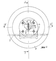
- Fig. 1 einen Teillängsschnitt durch ein Ausführungsbeispiel eines Klapplagers, bei welchem ein wippenartiger, in der Ausnehmung des Aufnahmeteiles gelagerter, gegen die Kraft einer Feder nachgiebiger Kupplungsvorsprung mit stirnseitigen Schlitzen des Zapfens der Wickelwelle zusammenwirkt,
- Fig. 2 eine Stirnseite des Klapplagers nach Fig. 1 mit einem Querschnitt durch den wippenartigen Kupplungsvorsprung nahe seiner Kupplungsoberfläche,
- Fig. 3 eine der Fig.2 entsprechende Darstellung mit einem Querschnitt durch den Kupplungsvorsprung im Bereich seiner Schwenklagerung,
- Fig. 4 einen Horizontalschnitt durch das Klapplager gemäß Fig. 1 und die Lagerstelle des Kupplungsvorsprunges, gemäß Linie IV - IV in Fig. 2,
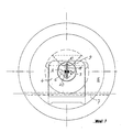
- Fig. 5 die Stirnseite einer abgewandelten Ausführungsform des Klapplagers, bei welcher der Kupplungsvorsprung als axial gegen die Kraft einer Feder eindrückbarer Stift oder Bolzen ausgebildet ist,
- Fig. 6 einen Längsschnitt durch ein Klapplager gemäß der Linie VI - VI in Fig. 5 und
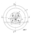
- Fig. 7 in schematischer Darstellung die Stirnseite eines Klapplagers gem. Fig.1 und einen zunächst noch seitlich versetzten Kupplungszapfen mit stirnseitigen Kupplungsschlitzen vor dem Einsetzen in die Ausnehmung des Aufnahmeteiles dieses Klapplagers.
- 1 is a partial longitudinal section through an embodiment of a folding bearing, in which a rocker-like, in the recess of the receiving part, resilient against the force of a spring coupling projection cooperates with frontal slots of the pin of the winding shaft,
- 2 shows an end face of the folding bearing according to FIG. 1 with a cross section through the rocker-like coupling projection near its coupling surface,
- 3 shows a representation corresponding to FIG. 2 with a cross section through the coupling projection in the region of its pivot bearing,
- 4 shows a horizontal section through the folding bearing according to FIG. 1 and the bearing point of the coupling projection, according to line IV-IV in FIG. 2,
- 5 shows the end face of a modified embodiment of the folding bearing, in which the coupling projection is designed as a pin or bolt which can be pressed in axially against the force of a spring,
- 6 shows a longitudinal section through a folding bearing along the line VI - VI in FIGS. 5 and
- Fig. 7 shows a schematic representation of the end face of a folding storage. Fig.1 and an initially laterally offset coupling pin with front coupling slots before insertion into the recess of the receiving part of this folding bearing.
Ein in beiden Ausführungsbeispielen jeweils im ganzen mit 1 bezeichnetes Klapplager zum Kuppeln von Wickelstäben mit einer Mitnehmerwelle 2 bei von einer Rolle oder auf eine Rolle arbeitenden Maschinen weist in aus dem Stand der Technik bekannter Weise ein eine Kupplungsausnehmung 3 enthaltendes Aufnahmeteil 4 auf. Der nicht näher darge-stellte Wickelstab hat an seinen Enden einen im Ausführungsbeispiel im Querschnitt vierkantigen Zapfen 5, dessen Querschnitt gem. Fig. 1 und 5 die Ausnehmung 3 und vor allem in dieser befindliche Kupplungsflächen 6 entsprechen. Der Zapfen 5 ist somit formschlüssig in die Ausnehmung 3 des Aufnahmeteiles 4 einsetzbar und auch wieder aus dieser nach oben aushebbar, wenn sich ein zu diesem Klapplager 1 gehöriges, um eine in Aushebeposition horizontale Achse 7 schwenkbares Handrad 8 in der in Fig. 1 mit strichpunktierten Linien dargestellten Öffnungsposition befindet. In Gebrauchsstellung ist der Zapfen 5 von einem an dem schwenkbaren und mitdrehenden Handrad 8 befindlichen Verschlußteil 9 übergriffen, wobei im Ausführungsbeispiel dieser Verschlußteil 9 ebenfalls eine winkelförmige Ausnehmung 10 hat, mit welcher die beim Einlegen oberste Kante 5a des Mehrkantes 5 umschlossen wird. In Schließstellung kann also das Drehmoment in diesem Klapplager über den Vierkant 5 und die entsprechende Ausnehmung 3 des Aufnahmeteiles 4 sowie den Verschlußteil 9 gut übertragen werden.A folding bearing, designated 1 in each of the two exemplary embodiments, for coupling winding bars with a
Bevor jedoch das Handrad 8 in Schließstellung gelangt,könnte beim Anlaufen der Welle 2 bzw. des Zapfens 5 an den schräg liegenden Kupplungsflächen 6 eine Kraftkomponente in Ausheberichtung des Zapfens 5 auftreten. Deshalb ist an der Stirnseite 11 des Zapfens 5 und der entsprechenden Gegenfläche 12 der Ausnehmung 3 des Aufnahmeteiles 4 eine beim Einsetzen des Zapfens 5 wirksam werdende, im folgenden noch näher zu beschreibende Kupplung vorgesehen, die das Anlaufdrehmoment übertragen und somit die schrägen Kupplungsflächen 6 entlasten kann, so daß dort keine Kraftkomponente auftreten kann, die ausreicht, die Wickelwelle aus ihrer Funktionsstellung anzuheben, bevor das Handrad 8 in Schließstellung gelangt ist.However, before the
Bei beiden Ausführungsbeispielen weist dabei die erwähnte Kupplung an der Stirnseite des Zapfens 5 zwischen Zapfen 5 und Aufnahmeteil 4 zwei formschlüssig ineinandergreifende Kupplungselemente auf, deren eines in der Wellenaufnahme 4 und deren anderes an der Stirnseite 11 des Zapfens5 angeordnet sind.In both exemplary embodiments, the coupling mentioned on the front side of the
In beiden Ausführungsbeispielen ist dabei als das eine Kupplungselement wenigstens ein in Einlegerichtung orientierter, nach der Aushebeseite offen mündender Schlitz 13 und als das andere Kupplungselement wenigstens ein in Gebrauchsstellung und in Drehrichtung formschlüssig in diesen Schlitz 13 eingreifender, ein Drehmoment übertragender, gegenüber der Zapfenmitte M exzentrischer Vorsprung 14 vorgesehen.In both exemplary embodiments, the one coupling element is at least one of which is oriented in the insertion direction and is open on the lifting side
Wiederum in beiden Ausführungsbeispielen mit dem vierkantigen Zapfen 5 ist dabei dieser als Kupplungselement dienender etwa nutenförmige Schlitz 13 an der Stirnseite 11 des Zapfens 5 vorgesehen und mündet an der beim Einsetzen am tiefsten liegenden Kante 5 b dieses Vierkant-Zapfens 5 randoffen. Der Kupplungsvorsprung 14 ist somit in der Wellenaufnahme 3 angeordnet.Again, in both exemplary embodiments with the
Es wäre auch eine umgekehrte Anordnung denkbar, bei welcher der Schlitz 13 in der vertikalen Gegenfläche 12 der Ausnehmung 3 des Aufnahmeteiles 4 in der Bewegungsrichtung des Zapfens 5 bei seinem Einsetzen orientiert angeordnet und nach der Oberseite der Ausnehmung 3 des Aufnahmeteiles 4 mündet. Der Kupplungsvorsprung 14 könnte dann an der Stirnseite 11 des Zapfens 5 exzentrisch angeordnet vorstehen. Eine solche Anordnung wäre vor allem bei einem Klapplager sinnvoll, bei dem der Zapfen 5 einen teilweise kreisrunden Querschnitt haben soll. Aber auch bei einem im Querschnitt kreisrunden Zapfen 5 könnte der Schlitz an der Strinseite 11 des Zapfens 5 und der Vorsprung 14 in dem Aufnahmeteil 4 angeordnet sein, wobei unter Umständen bei genügend starker Ausbildung dieser Kupplungsteile sogar eine weitere Drehmomentübertragung an der Längsseite des Zapfens 5 ganz entfallen könnte, wenn die zu übertragenden Kräfte genügend gering sind, um dies zuzulassen. Es ergäbe sich dann der Vorteil eines sehr preiswerten, weil im Querschnitt kreisrunden, Zapfens 5.An inverted arrangement would also be conceivable, in which the
In den Figuren 1, 4, 6 und 7 erkennt man, daß der Kupplungsschlitz 13 an dem Zapfen 5 über dessen gesamte Stirnseite verläuft und an seinen beiden Enden randoffen ist, so daß der Zapfen 5 in zwei einander um 180° entgegengesetzten Orientierungen problemlos eingesetzt werden kann. Dabei ist vor allem in Fig. 7 angedeutet, daß mehrere - in diesem Falle des im Querschnitt quadratischen Zapfens 5 - zwei sich kreuzende Kupplungsschlitze 13 an der Stirnseite 11 des Zapfens 5 vorgesehen sein können, die jeweils im Bereich einer Kante randoffen münden. Dadurch kann jede für das Einsetzen und Ausheben brauchbare Position des Zapfens 5 zu der gewünschten stirnseitigen Kupplung führen. Bei dem in den Ausführungsbeispielen vorgesehenen Vierkant als Wellenzapfen 5 sind demgemäß zwei auf den Diagonalen der Stirnseiten 11 dieser Vierkante verlaufende randoffene Schlitze 13 vorgesehen.In Figures 1, 4, 6 and 7 it can be seen that the
In Fig. 4 ist angedeutet, daß der Kupplungsvorsprung 14 in seiner Breite oder seitlichen Ausdehnung der Weite des Kupplungsschlitzes 13 entspricht, um möglichst spielfrei ein Drehmoment übertragen zu können.In Fig. 4 it is indicated that the
Die dargestellten Ausführungsbeispiele haben außerdem eine Ausgestaltung gemeinsam, die zum Ausgleich eines nicht lagegerechten Einlegens des Zapfens 5 dienen, wie dies in Fig.7 angedeutet ist. Dazu ist der Kupplungsvorsprung 14 nachgiebig, im Ausführungsbeispiel jeweils federbelastet und hat eine in Einlegerichtung mehr und mehr vorstehende Schrägfläche 15 zum Zurückdrängen durch das Einlegen des Wellenzapfens 5 und dessen Stirnseite 11 an nicht geschlitzten Bereichen gegen die Kraft der Feder 16. Ist dann der Zapfen 5 in die lagegerechte Position zentriert, kann der federbelastete Kupplungsvorsprung 14 in die entsprechende Gegenausnehmung einrasten und einspringen und formschlüssig eingreifen.The illustrated exemplary embodiments also have a configuration in common, which serve to compensate for incorrect insertion of the
In dem Ausführungsbeispiel gemäß den Figuren 1 bis 4 ist der Kupplungsvorsprung 14 wippenartig ausgebildet und um eine quer zur Einsteckrichtung des Zapfens 5 orientierte Achse A schwenkbar. Dabei liegt diese Achse A in Gebrauchsstellung etwa auf der Mitte M des Zapfens 5 und der Welle 2 und der tieferliegende Arm 14 a dieser Wippe bildet praktisch den schrägen, unter Umständen durch den Wellenzapfen 5 bis zum Eintritt in den Kupplungsschlitz gegen die Kraft der Feder 16 verstellbaren Kupplungsvorsprung. In Fig. 1 erkennt man deutlich diesen Arm 14 a, welcher mit einem dem Zapfen 5 zugewandten Bereich 14 gleichzeitig den Kupplungsvorsprung bildet und dort auch die von oben nach unten mehr und mehr vorstehende Schrägfläche 15 hat, an welcher die Stirnseite 11 des Zapfens 5 angreifen kann, falls nicht der Schlitz 13 sofort über den Vorsprung 14 greift. Bei einem Angriff eines ungeschlitzten Bereiches der Stirnseite 11 an der Schrägfläche 15 wird somit die Wippe um ihre Achse A verschwenkt, wobei der Arm 14 a mit einem Vorsprung 14b gegen die in einer Ausnehmung 17 angeordnete Feder drückt und diese im Sinne der gewünschten Rückstellkraft spannt. Gelangt dann bei der weiteren Einlegebewegung des Zapfens 5 durch die Zentrierung der Kupplungsflächen 16 der Schlitz 13 in die gewünschte Position, kann die Feder 16 den Kupplungsvorsprung 14 in den Schlitz 13 einrücken und so die gewünschte in Drehrichtung formschlüssige Kupplung herstellen. Dabei erkennt man in Fig. 4, daß die dabei in Berührung miteinander gelangenden seitlichen Flächen 18 des Kupplungsvorsprunges 14 und die Seitenwände 19 des Schlitzes 13 parallel zueinanderliegen, so daß das Ein- und Ausrücken einfach ist, dennoch aber ein Drehmoment übertragen werden kann, ohne daß daraus eine Belastung des nachgiebigen Kupplungsvorsprunges 14 in Löseposition der Kupplung auftreten kann.In the exemplary embodiment according to FIGS. 1 to 4, the
Der Kupplungsvorsprung 14 ist dabei mittels zweier seitlich vorspringender Köpfe, im Ausführungsbeispiel Nietenköpfe 20 schwenkbar in einer diese Köpfe 20 umschließenden Öffnung, gemäß Fig. 1 einem von oben zugänglichen Schlitz 21, gehalten und durch Seitenwände 22 zumindest bereichsweise seitlich geführt, so daß einerseits die konstruktive Anordnung dieses wippenartigen Kupplungsvorsprunges 14 einfach ist und er andererseits präzise und genügend genau arbeiten kann.The
Im Ausführungsbeispiel gemäß den Figuren 5 und 6 ist der Kupplungsvorsprung 14 ein in dem Aufnahmeteil 4 etwa parallel zu der Erstreckung der Welle 2 und des Zapfens 5 vorstehender, wiederum durch eine Druckfeder 16 belasteter Stift, dessen vorstehendes Ende in Gebrauchsstellung exzentrisch in den Kupplungsschlitz 13 des Zapfens 5 als Kupplungsvorsprung 14 eingreift. In Fig. 6 erkennt man, daß dabei das vorstehende Ende dieses Stiftes abgerundet ist, so daß diese Formgebung wiederum der Schräge 15 im Ausführungsbeispiel nach Fig. 1 entspricht und in gleicher Weise wirksam wirken kann, indem nämlich bei einem nicht lagegerechten Einsetzen des Kupplungszapfens ungeschlitzte Bereiche seiner Stirnseite 11 diesen Stift und somit den gesamten Kupplungsvorsprung 14 gegen die Kraft der Feder 16 zurückschieben können, bis sich der Schlitz 13 in der Position befindet, in welcher der Kupplungsvorsprung in ihn eingreifen kann. Dabei zeigt Fig. 6 außerdem, daß der Kupplungsstift wiederum in einer Führungsbohrung 17 des Aufnahmeteiles 4 zusammen mit der Feder 16 angeordnet ist, wobei er nahe der unteren Spitze oder Umrißlinie des Querschnittes der Ausnehmung 3 dieses Aufnahmeteiles 4 mit größtmöglicher Exzentrizität zur Wellenmitte M angeordnet ist, um günstige Hebeverhältnisse für die Drehmomentenübertragung zu schaffen. Der als Kupplungsvorsprung 14 dienende Stift hat dabei ein Langloch 23, mit welchem er an einem ihn quer durchsetzenden Querstift 24 in Verschieberichtung gegen die Druckkraft seiner Druckfeder 16 geführt ist. In Fig. 5 ist angedeutet, wie dieser Querstift von der Seite her in der Wellenaufnahme 4 angeordnet werden kann. Es zeigt sich, daß vor allem diese Ausführungsform auch an schon bestehenden Klapplagern 1 nachträglich angebracht werden kann, indem die Bohrung 17 und eine Querbohrung 25 für den Querstift 24 angebracht werden, wonach bereits der Kupplungsvorsprung 14 in Form des federbelasteten Stiftes eingesetzt werden kann. Somit kann dann in ein solches nachgerüstetes Klapplager 1 ein mit stirnseitigen Kupplungsschlitzen 13 versehener Zapfen eingesetzt werden, der die vorbeschriebenen Vorteile hat.In the exemplary embodiment according to FIGS. 5 and 6, the
Ist ein Wellenzapfen 5 in der erfindungsgemäßen Weise in die Ausnehmung 3 des Aufnahmeteiles 4 des Klapplagers 1 eingesetzt und dabei selbsttätig zentriert und außerdem stirnseitig gekuppelt worden, kann der den Zapfen 5 aufweisende Wickelstab anlaufen, ohne daß an den schrägen Kupplungsflächen 6 eine derartige Kraftkomponente auftritt, daß dadurch der Zapfen 5 seine mit der Welle 2 fluchtende Lage wieder verläßt. Somit kann das Verschließen des Handrades 8 ungestört erfolgen, wonach die endgültige und sichere Kupplung zwischen Wickelstab und Mitnehmerwelle 2 beendet ist, ohne daß es einer speziellen Hilfsvorrichtung für das Schließen des Handrades 8 bedarf. Dennoch können die Vorteile von sich in Einlegerichtung annähernden Kupplungsflächen 6 für die gute Zentrierung des Zapfens 5 ausgenutzt werden.If a
Claims (16)
Priority Applications (1)
| Application Number | Priority Date | Filing Date | Title |
|---|---|---|---|
| AT86116883T ATE45555T1 (en) | 1986-02-14 | 1986-12-04 | FOLDING BEARING FOR COUPLING COIL BARS WITH A DRIVE SHAFT. |
Applications Claiming Priority (2)
| Application Number | Priority Date | Filing Date | Title |
|---|---|---|---|
| DE3604611 | 1986-02-14 | ||
| DE3604611A DE3604611C1 (en) | 1986-02-14 | 1986-02-14 | Folding bearing for coupling winding bars with a drive shaft |
Publications (2)
| Publication Number | Publication Date |
|---|---|
| EP0237635A1 EP0237635A1 (en) | 1987-09-23 |
| EP0237635B1 true EP0237635B1 (en) | 1989-08-16 |
Family
ID=6294058
Family Applications (1)
| Application Number | Title | Priority Date | Filing Date |
|---|---|---|---|
| EP86116883A Expired EP0237635B1 (en) | 1986-02-14 | 1986-12-04 | Bearing for coupling winding shafts to a driving shaft |
Country Status (5)
| Country | Link |
|---|---|
| US (1) | US4758113A (en) |
| EP (1) | EP0237635B1 (en) |
| JP (1) | JPH07112896B2 (en) |
| AT (1) | ATE45555T1 (en) |
| DE (1) | DE3604611C1 (en) |
Families Citing this family (9)
| Publication number | Priority date | Publication date | Assignee | Title |
|---|---|---|---|---|
| DE3706166C1 (en) * | 1987-02-26 | 1988-04-21 | Boschert Gmbh & Co Kg Ludwig | Folding storage |
| DE8816525U1 (en) * | 1988-06-30 | 1989-10-19 | Ludwig Boschert Maschinen- und Apparatebau GmbH & Co KG, 7850 Lörrach | Device for coupling a winding rod or similar with a drive shaft |
| DE4137921A1 (en) * | 1991-11-18 | 1993-05-19 | Windmoeller & Hoelscher | DEVICE FOR COUPLING A REEL SHAFT PIN WITH A DRIVE SHAFT PIN |
| AT408339B (en) * | 1992-08-05 | 2001-10-25 | Schindlecker Franz Ing | FOLDING BEARING |
| FR2707275B1 (en) * | 1993-02-09 | 1995-09-29 | Guttin Sarl Ets Christian | Rocking bearing intended to carry one end of a winding bar, for the winding or unwinding of sheets of material. |
| ITVI940158A1 (en) * | 1994-10-28 | 1995-01-28 | QUICK RELEASE END SUPPORT PARTICULARLY FOR SPOOL-HOLDER AXES. | |
| DE19712443C2 (en) * | 1997-03-25 | 1999-09-23 | Boschert Ludwig Masch | Device for coupling a winding bar with a drive shaft |
| TW526905U (en) * | 2002-07-12 | 2003-04-01 | Shi-Tsai Chen | Joint shaft device |
| DE102009032642B3 (en) * | 2009-07-10 | 2011-02-03 | Ludwig Boschert Maschinen- Und Apparatebau Gmbh & Co Kg | Device for controllable detaching of web from sleeve, has support including bar that runs radially axial to winding shaft, and sensor detecting inertia of sleeve for detecting elastic deformation of bar caused by inertia of sleeve |
Family Cites Families (9)
| Publication number | Priority date | Publication date | Assignee | Title |
|---|---|---|---|---|
| DE917592C (en) * | 1952-08-15 | 1954-09-06 | Faerberei & Appretur Schutster | Device for coupling winding bars |
| US3147985A (en) * | 1961-08-28 | 1964-09-08 | Armstrong Cork Co | Driving chuck |
| US3368769A (en) * | 1966-08-23 | 1968-02-13 | West Virginia Pulp & Paper Co | Tapered core chuck with floating key |
| DE2852510C2 (en) * | 1978-12-05 | 1983-10-27 | Kunz Maschinen- und Apparatebau GmbH, 7850 Lörrach | Device for coupling winding bars |
| DE7923201U1 (en) * | 1979-08-14 | 1979-11-08 | Kunz Masch App | DEVICE FOR COUPLING A COILING ROD OR DGL. WITH A DRIVE SHAFT |
| DE3026904C2 (en) * | 1980-07-16 | 1983-12-22 | Kunz Maschinen- und Apparatebau GmbH, 7850 Lörrach | Slidable bearing for a shaft or roller bearing |
| DE3127553C2 (en) * | 1981-07-11 | 1983-11-10 | Kunz Maschinen- und Apparatebau GmbH, 7850 Lörrach | Folding stock |
| DD200911B1 (en) * | 1981-09-18 | 1987-01-21 | Pentacon Dresden Veb | SWITCH CLUTCH FOR RING TABLES |
| DE3228739C1 (en) * | 1982-07-31 | 1984-02-02 | Kunz Maschinen- und Apparatebau GmbH, 7850 Lörrach | Device for coupling a winding bar with a drive shaft |
-
1986
- 1986-02-14 DE DE3604611A patent/DE3604611C1/en not_active Expired
- 1986-12-04 AT AT86116883T patent/ATE45555T1/en not_active IP Right Cessation
- 1986-12-04 EP EP86116883A patent/EP0237635B1/en not_active Expired
-
1987
- 1987-02-13 US US07/014,938 patent/US4758113A/en not_active Expired - Lifetime
- 1987-02-13 JP JP62029954A patent/JPH07112896B2/en not_active Expired - Lifetime
Also Published As
| Publication number | Publication date |
|---|---|
| DE3604611C1 (en) | 1987-04-16 |
| US4758113A (en) | 1988-07-19 |
| JPS62191347A (en) | 1987-08-21 |
| EP0237635A1 (en) | 1987-09-23 |
| JPH07112896B2 (en) | 1995-12-06 |
| ATE45555T1 (en) | 1989-09-15 |
Similar Documents
| Publication | Publication Date | Title |
|---|---|---|
| DE69514988T2 (en) | Centrifuge with removable rotor and a device for axially locking the rotor on the drive shaft | |
| DE69703635T2 (en) | Driven locking device for vehicles with improved means for limiting the movement of a bolt | |
| DE3720018C2 (en) | SPRING TENSIONER | |
| DE3433877C1 (en) | Dental handpiece | |
| DE2913885C2 (en) | Louvre blind with vertically arranged slats | |
| EP0237635B1 (en) | Bearing for coupling winding shafts to a driving shaft | |
| EP0458170B1 (en) | Chuck | |
| CH644080A5 (en) | DEVICE FOR COUPLING WRAPPING RODS. | |
| DE3822106C1 (en) | ||
| DE2549556B2 (en) | VALVE ACTUATION MECHANISM WITH ONE MOTOR AND ONE MANUAL DRIVE | |
| DE2112257A1 (en) | Replaceable tooth | |
| EP0256245B1 (en) | Tool holder for a folding machine or the like | |
| DE2818897C2 (en) | Drive device, in particular for a coffee machine | |
| EP0101544B1 (en) | Device for coupling a coiling core to a driving shaft | |
| WO2019141583A1 (en) | Pull-out guide for a drawer and method for aligning a drawer on a pull-out guide | |
| DE3018633C2 (en) | Electric hammer drill with switchable drill drive | |
| CH639709A5 (en) | ROTATIONAL SHAFT. | |
| DE8603908U1 (en) | Folding bearing for coupling winding bars with a drive shaft | |
| CH700442A1 (en) | Locking device for a bobbin case for a lower thread bobbin. | |
| DE2117585A1 (en) | Device for locking the slide of an automatic maintenance device in the maintenance position | |
| DE3879152T2 (en) | RECORDING AND PLAYING DEVICE. | |
| DE69104691T2 (en) | Safety device for a roving machine, which is provided with an automatic pick-up device. | |
| DE2621857C3 (en) | Steering and ignition lock | |
| DE69917089T2 (en) | Spindle for abrasive tape strip and device to replace it with a new strip | |
| EP0267480A2 (en) | Ink ribbon cartridge drive mechanism and cooperating ink ribbon cartridge |
Legal Events
| Date | Code | Title | Description |
|---|---|---|---|
| PUAI | Public reference made under article 153(3) epc to a published international application that has entered the european phase |
Free format text: ORIGINAL CODE: 0009012 |
|
| 17P | Request for examination filed |
Effective date: 19870611 |
|
| AK | Designated contracting states |
Kind code of ref document: A1 Designated state(s): AT CH ES FR GB IT LI |
|
| 17Q | First examination report despatched |
Effective date: 19881021 |
|
| GRAA | (expected) grant |
Free format text: ORIGINAL CODE: 0009210 |
|
| AK | Designated contracting states |
Kind code of ref document: B1 Designated state(s): AT CH ES FR GB IT LI |
|
| PG25 | Lapsed in a contracting state [announced via postgrant information from national office to epo] |
Ref country code: IT Free format text: LAPSE BECAUSE OF FAILURE TO SUBMIT A TRANSLATION OF THE DESCRIPTION OR TO PAY THE FEE WITHIN THE PRE;WARNING: LAPSES OF ITALIAN PATENTS WITH EFFECTIVE DATE BEFORE 2007 MAY HAVE OCCURRED AT ANY TIME BEFORE 2007. THE CORRECT EFFECTIVE DATE MAY BE DIFFERENT FROM THE ONE RECORDED.SCRIBED TIME-LIMIT Effective date: 19890816 |
|
| REF | Corresponds to: |
Ref document number: 45555 Country of ref document: AT Date of ref document: 19890915 Kind code of ref document: T |
|
| PG25 | Lapsed in a contracting state [announced via postgrant information from national office to epo] |
Ref country code: ES Free format text: LAPSE BECAUSE OF FAILURE TO SUBMIT A TRANSLATION OF THE DESCRIPTION OR TO PAY THE FEE WITHIN THE PRESCRIBED TIME-LIMIT Effective date: 19891127 |
|
| ET | Fr: translation filed | ||
| GBT | Gb: translation of ep patent filed (gb section 77(6)(a)/1977) | ||
| PLBE | No opposition filed within time limit |
Free format text: ORIGINAL CODE: 0009261 |
|
| STAA | Information on the status of an ep patent application or granted ep patent |
Free format text: STATUS: NO OPPOSITION FILED WITHIN TIME LIMIT |
|
| 26N | No opposition filed | ||
| REG | Reference to a national code |
Ref country code: CH Ref legal event code: PUE Owner name: BOSCHERT GMBH & CO. KG |
|
| REG | Reference to a national code |
Ref country code: GB Ref legal event code: 732E |
|
| REG | Reference to a national code |
Ref country code: FR Ref legal event code: TP |
|
| PGFP | Annual fee paid to national office [announced via postgrant information from national office to epo] |
Ref country code: FR Payment date: 20011115 Year of fee payment: 16 |
|
| PGFP | Annual fee paid to national office [announced via postgrant information from national office to epo] |
Ref country code: GB Payment date: 20011129 Year of fee payment: 16 |
|
| PGFP | Annual fee paid to national office [announced via postgrant information from national office to epo] |
Ref country code: CH Payment date: 20011224 Year of fee payment: 16 |
|
| PGFP | Annual fee paid to national office [announced via postgrant information from national office to epo] |
Ref country code: AT Payment date: 20011228 Year of fee payment: 16 |
|
| REG | Reference to a national code |
Ref country code: GB Ref legal event code: IF02 |
|
| PG25 | Lapsed in a contracting state [announced via postgrant information from national office to epo] |
Ref country code: GB Free format text: LAPSE BECAUSE OF NON-PAYMENT OF DUE FEES Effective date: 20021204 Ref country code: AT Free format text: LAPSE BECAUSE OF NON-PAYMENT OF DUE FEES Effective date: 20021204 |
|
| PG25 | Lapsed in a contracting state [announced via postgrant information from national office to epo] |
Ref country code: CH Free format text: LAPSE BECAUSE OF NON-PAYMENT OF DUE FEES Effective date: 20021231 Ref country code: LI Free format text: LAPSE BECAUSE OF NON-PAYMENT OF DUE FEES Effective date: 20021231 |
|
| GBPC | Gb: european patent ceased through non-payment of renewal fee | ||
| REG | Reference to a national code |
Ref country code: CH Ref legal event code: PL |
|
| PG25 | Lapsed in a contracting state [announced via postgrant information from national office to epo] |
Ref country code: FR Free format text: LAPSE BECAUSE OF NON-PAYMENT OF DUE FEES Effective date: 20030901 |
|
| REG | Reference to a national code |
Ref country code: FR Ref legal event code: ST |