EP0237599A1 - Pneumatic radial tire for passenger car - Google Patents
Pneumatic radial tire for passenger car Download PDFInfo
- Publication number
- EP0237599A1 EP0237599A1 EP86103737A EP86103737A EP0237599A1 EP 0237599 A1 EP0237599 A1 EP 0237599A1 EP 86103737 A EP86103737 A EP 86103737A EP 86103737 A EP86103737 A EP 86103737A EP 0237599 A1 EP0237599 A1 EP 0237599A1
- Authority
- EP
- European Patent Office
- Prior art keywords
- belt
- layer
- tread portion
- fiber cords
- carcass layer
- Prior art date
- Legal status (The legal status is an assumption and is not a legal conclusion. Google has not performed a legal analysis and makes no representation as to the accuracy of the status listed.)
- Granted
Links
- 229920000049 Carbon (fiber) Polymers 0.000 claims abstract description 39
- 239000004917 carbon fiber Substances 0.000 claims abstract description 39
- VNWKTOKETHGBQD-UHFFFAOYSA-N methane Chemical compound C VNWKTOKETHGBQD-UHFFFAOYSA-N 0.000 claims abstract description 36
- 239000000835 fiber Substances 0.000 claims abstract description 34
- 239000004760 aramid Substances 0.000 claims abstract description 32
- 229920003235 aromatic polyamide Polymers 0.000 claims abstract description 32
- 239000011324 bead Substances 0.000 claims description 10
- 238000010438 heat treatment Methods 0.000 claims description 2
- 229910000831 Steel Inorganic materials 0.000 description 16
- 239000010959 steel Substances 0.000 description 16
- 230000003014 reinforcing effect Effects 0.000 description 12
- 238000010586 diagram Methods 0.000 description 4
- 238000011056 performance test Methods 0.000 description 3
- 238000005452 bending Methods 0.000 description 2
- 230000000694 effects Effects 0.000 description 2
- 229920000728 polyester Polymers 0.000 description 2
- 238000000926 separation method Methods 0.000 description 2
- 239000000853 adhesive Substances 0.000 description 1
- 230000001070 adhesive effect Effects 0.000 description 1
- 238000005096 rolling process Methods 0.000 description 1
Images

Classifications
-
- B—PERFORMING OPERATIONS; TRANSPORTING
- B60—VEHICLES IN GENERAL
- B60C—VEHICLE TYRES; TYRE INFLATION; TYRE CHANGING; CONNECTING VALVES TO INFLATABLE ELASTIC BODIES IN GENERAL; DEVICES OR ARRANGEMENTS RELATED TO TYRES
- B60C9/00—Reinforcements or ply arrangement of pneumatic tyres
- B60C9/18—Structure or arrangement of belts or breakers, crown-reinforcing or cushioning layers
- B60C9/26—Folded plies
Definitions
- This invention relates generally to a pneumatic radial tire for a passenger car, and more specifically to a pneumatic radial tire for a passenger car having an improved belt layer structure in order to improve high speed performance and driving comfortableness of the tire and to reduce the tire weight.
- a carcass layer having its reinforcing cords arranged substantially at 90° to a tire circumferential direction is disposed between a pair of right and left bead portions and is covered with a plurality of belt layers reinforced by steel cords. Therefore, the steel radial tires exhibit various excellent properties as the tire in high speed performance, driving stability, wear resistance, low rolling resistance, and so forth.
- the steel radial tire is not yet free from the problem in that driving comfortableness is not high because a plurality of belt layers reinforced by the steel cords are hard and stiff.
- the weight of the steel radial tire has been reduced recently to such a level which is substantially equal to that of bias tires of an equivalent size, but further reduction of the tire weight seems to have reached the limit.
- a pneumatic radial tire for a passenger car of the type which consists of a pair of right and left bead portions, a pair of right and left side wall portions continuing the bead portions, respectively, and a tread portion interposed between the side wall portions, and in which a carcass layer having a cord angel in the range of 70° to 90° to a tire circumferential direction is mounted between the bead portions and a plurality of belt layers crossing one another at a cord angle in the range of 10° to 35° to the tire circumferential direction are disposed on the carcass layer at the tread portion
- the object of the present invention described above can be accomplished by a pneumatic radial tire for a passenger car which is characterized in that:
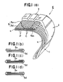
- FIGs. 1(a) through 1(d) show some preferred embodiments of the present invention, wherein:
- symbol E represents a pneumatic radial tire for a passenger car in accordance with the first embodiment of the present invention.
- This radial tire consists of a pair of right and left bead portions 1, 1, a pair of right and left side wall portions 2, 2 continuing the bead portions 1, 1 and a tread portion 3 interposed between the side wall portions 2, 2.
- a carcass layer 4 whose cord angle is from 70° to 90° to a tire circumferential direction is fitted between the right and left bead portions 1, 1, and a multi-layered belt layer 5 which cross one another at a cord angle of 10° to 35° to the tire circumferential direction is disposed on the carcass layer 4 at the tread portion 3.
- a belt layer 5d consisting of aromatic polyamide fiber cords P is disposed on the carcass layer side 4, and a belt layer 5u consisting of carbon fiber cords C is disposed on the tread portion side 3 close to the belt layer 5d.
- the carbon fiber cords C are used as the reinforcing cords of the belt layer 5u on the tread portion side as described above, comfortableness to drive can be improved drastically in comparison with the conventional steel radial tire for the same reason as in the case of the belt layer 5d on the carcass layer side which uses the aromatic polyamide fiber cords P as the reinforcing cords, and high speed performance can likewise be improved.
- the twist structure in this case may be a folded twist structure wherein several carbon fibers are first subjected to primary twisting and then several twisted fibers are subjected to final twisting, or a single twist structure wherein one filamentary carbon fiber is merely twisted.
- the end portions of at least one layer of the belt layers 5d on the carcass layer side consisting of the aromatic polyamide fiber cords P are bent towards the tread portion side 3, and these belt portions 5d1 cover the end portions of the belt layer 5u on the tread portion side consisting of the carbon fiber cords C.
- the end portions of the belt layer 5u on the tread portion side consisting of the carbon fiber cords C are covered with the bent portions 5d1 of the belt layer 5d on the carcass layer side consisting of the aromatic polyamide fiber cords P that have higher bending fatigue resistance than the belt layer 5u.
- one belt layer 5d consisting of the aromatic polyamide fiber cords P is disposed on the side of the carcass layer 4, while on layer of the belt layer 5u consisting of the carbon fiber cords C is disposed on the side of the tread portion 3 in the proximity of the belt layer 5d on the carcass layer side. Furthermore, both right and left end portions of the belt layer 5d on the carcass layer side consisting of the aromatic polyamide fiber cords P are bent towards the tread portion 3, and these bent portions 5d1 cover the right and left end portions of the belt layer 5u on the tread portion side consisting of the carbon fiber cords.
- two belt layers 5d consisting of the aromatic polyamide fiber cords P are disposed on the carcass layer side 4 while one belt layer 5u consisting of the carbon fiber cords C is disposed on the tread portion side 3 in the proximity of the belt layers 5d on the carcass layer side. Furthermore, one of the end portions of each belt layer 5d on the carcass layer side consisting of the aromatic polyamide fiber cords P is bent towards the tread portion 3 in such a manner as to face the bent end portion of the other belt layer 5d and to cover the right and left end portions of the belt layer 5u on the tread portion side consisting of the carbon fiber cords C.
- one belt layer 5d consisting of the aromatic polyamide fiber cords P is disposed on the carcass layer side 4 while two belt layers 5u consisting of the carbon fiber cords C are disposed on the tread portion side 3 in the proximity of the belt layer 5d. Furthermore, both right and left end portions of the belt layer 5d consisting of the aromatic polyamide fiber cords P are bent towards the tread portion 3 so that these bent portions 5d1 cover both right and left portions of the belt layers 5u consisting of the carbon fiber cords C.
- two belt layers 5d consisting of the aromatic polyamide fiber cords P are disposed on the carcass layer side 4 while one belt fiber 5u consisting of the carbon fiber cords C is disposed on the tread portion side 3 in the proximity of the belt layers 5d, and both right and left end portions of the lower layer of the belt layers 5d are bent towards the tread portion 3 in such a manner that the end portions 5d1 cover the right and left end portions of the belt layer 5u on the tread portion side consisting of the carbon fiber cords C.
- the projection tester is equipped with a semispherical projection of a 20 mm diameter at one position on the periphery of a drum which is 2,500 mm in diameter, and detects the axial force when the sample tire gets over the projection.
- the magnitude of this axial force is used as a representative value of the driving comfortability.
- the driving comfortability test was carried out at an air pressure of 2.0 kg/cm2, a load of 515 kg and speeds of 60 km/hr, 80 km/hr, 100 km/hr and 120 km/hr, respectively.
- the test results were shown in Fig. 2.
- the diagram represents the driving comfortability in terms of index using the test result of the conventional radial tire as 100.
- the air pressure was 3.0 kg/cm2 and the load was 515 kg but the speed was increased step-wise by 10 km/hr every 10 minutes until the tire was broken.
- the test result was shown in Fig. 3.
- the diagram represents the high speed performance in terms of index using the test result of the conventional radial tire as 100.
- the high speed performance could be improved by about 5% by the tire of the present invention when compared with the conventional radial tire.
- the present invention disposes the belt layer consisting of the aromatic polyamide fiber cords on the carcass layer side and the belt layer consisting of the carbon fiber cords on the tread portion side in the proximity of the belt layer on the carcass layer side. Furthermore, the end portions of at least one layer of the belt layers on the carcass layer side consisting of the aromatic polyamide fiber cords are bent towards the tread portions so that the bent portions cover the end portions of the belt layer on the tread portion side consisting of the carbon fiber cords. Therefore, the present invention can improve both high speed performance and driving comfortability, and can also reduce the tire weight.
Landscapes
- Engineering & Computer Science (AREA)
- Mechanical Engineering (AREA)
- Tires In General (AREA)
Abstract
Description
- This invention relates generally to a pneumatic radial tire for a passenger car, and more specifically to a pneumatic radial tire for a passenger car having an improved belt layer structure in order to improve high speed performance and driving confortableness of the tire and to reduce the tire weight.
- Requirements for tires have become severer and severer in recent years with the development in highways, and steel radial tires have replaced conventional bias tires as the tires that satisfy these requirements.
- In steel radial tires, a carcass layer having its reinforcing cords arranged substantially at 90° to a tire circumferential direction is disposed between a pair of right and left bead portions and is covered with a plurality of belt layers reinforced by steel cords. Therefore, the steel radial tires exhibit various excellent properties as the tire in high speed performance, driving stability, wear resistance, low rolling resistance, and so forth.
- However, the steel radial tire is not yet free from the problem in that driving comfortableness is not high because a plurality of belt layers reinforced by the steel cords are hard and stiff.
- In conjunction with the tire weight, the weight of the steel radial tire has been reduced recently to such a level which is substantially equal to that of bias tires of an equivalent size, but further reduction of the tire weight seems to have reached the limit.
- Since a plurality of belt layers reinforced by the steel cords have great mass, the belt layers are likely to swell up due to the centrifugal force of the tire at the time of high speed rotation, whereby so-called "separation" is likely to occur at both end portions of the belt layers. Thus, the steel radial tire has reached the limit in the aspect of high speed performance, too.
- Therefore, it is an object of the present invention to provide an excellent pneumatic radial tire for a passenger car employing an improved belt layer structure in order to improve high speed performance and driving comfortableness and to reduce the tire weight.
- In a pneumatic radial tire for a passenger car of the type which consists of a pair of right and left bead portions, a pair of right and left side wall portions continuing the bead portions, respectively, and a tread portion interposed between the side wall portions, and in which a carcass layer having a cord angel in the range of 70° to 90° to a tire circumferential direction is mounted between the bead portions and a plurality of belt layers crossing one another at a cord angle in the range of 10° to 35° to the tire circumferential direction are disposed on the carcass layer at the tread portion, the object of the present invention described above can be accomplished by a pneumatic radial tire for a passenger car which is characterized in that:
- (1) among the belt layers described above, a belt layer or layers consisting of aromatic polyamide fiber cords are disposed on the side of the carcass layer, and a belt layer or layers consisting of carbon fiber cords are disposed on the side of the tread portion in the proximity of the belt layer(s) on the carcass layer side; and
- (2) the end portions of at least one belt layer consisting of the aromatic polyamide fiber cords on the side of the carcass layer are bent so that the bent portions cover the end portions of the belt layer(s) consisting of the carbon fiber cords on the side of the tread portion.
- The above and other objects and novel features of the present invention will become more apparent from the following description when taken in conjunction with the accompanying drawings.
- Figs. 1(a) through 1(d) show some preferred embodiments of the present invention, wherein:
- Fig. 1(a) is a partial cut-away perspective view of a first embodiment; and
- Figs. 1(b) through 1(d) are schematic views, each showing the principal portions, of second to fourth embodiments;
- Fig. 2 is a diagram showing the result of the test for comfortableness to drive; and
- Fig. 3 is a diagram showing the result of the test for high speed performance.
- In Fig. 1(a), symbol E represents a pneumatic radial tire for a passenger car in accordance with the first embodiment of the present invention. This radial tire consists of a pair of right and left bead portions 1, 1, a pair of right and left side wall portions 2, 2 continuing the bead portions 1, 1 and a
tread portion 3 interposed between the side wall portions 2, 2. Acarcass layer 4 whose cord angle is from 70° to 90° to a tire circumferential direction is fitted between the right and left bead portions 1, 1, and amulti-layered belt layer 5 which cross one another at a cord angle of 10° to 35° to the tire circumferential direction is disposed on thecarcass layer 4 at thetread portion 3. - (1) In the present invention, among the
belt layer 5 described above, abelt layer 5d consisting of aromatic polyamide fiber cords P is disposed on thecarcass layer side 4, and abelt layer 5u consisting of carbon fiber cords C is disposed on thetread portion side 3 close to thebelt layer 5d. - Since the aromatic polyamide fiber cords P are used as the reinforcing cords for the
belt layer 5d on the carcass layer side as described above, this embodiment provides the following effects. - (a) In comparison with the belt layer of the conventional steel radial tire which is reinforced by steel cords, the outward bending rigidity of the surface of the belt layer can be reduced. Therefore, impact force at the time of getting over a projection can be mitigated and comfortableness to drive can be drastically improved.
- (b) When the total strength remains the same, this embodiment can reduce the weight in comparison with the belt layer using the steel cords as the reinforcing cords. Therefore, high speed performance can be improved.
- The aromatic polyamide fiber cords P to be used as the reinforcing cords of the
belt layer 5d on the carcass layer side are preferably produced by twisting aromatic polyamide fibers having properties of tensile strength of at least 150 kg/mm² and tensile elastic modulus of at least 3,000 kg/mm³ in such a fashion that a twist coefficient K expressed by the following formula is in the range of 1,000 ≦ K ≦ 2,500 to form the cords and then subjecting the cords to bonding heat-treatment:
K = T √D
where
K ... twist coefficient,
T ... number of twists of cord (turns/10 cm),
D ... total denier of cord. - In the present invention, since the carbon fiber cords C are used as the reinforcing cords of the
belt layer 5u on the tread portion side as described above, comfortableness to drive can be improved drastically in comparison with the conventional steel radial tire for the same reason as in the case of thebelt layer 5d on the carcass layer side which uses the aromatic polyamide fiber cords P as the reinforcing cords, and high speed performance can likewise be improved. - Preferably, the carbon fiber cords C to be used as the reinforcing cords of the
belt layer 5u on the tread portion side are prepared by putting 10 to 50%, based on the unit length of the carbon fiber, of an adhesive to the carbon fiber having tensile strength of at least 100 kg/mm² and preferably at least 200 kg/mm² and tensile elastic modulus of at least 5,000 kg/mm² and preferably at least 15,000 kg/mm², and then twisting the carbon fiber cords in such a fashion that the twist coefficient K expressed by the following formula is within the range of 0 ≦ K ≦ 1,800:
K = T√D
where
K ... twist coefficient,
T ... number of twists of cord (turns/10 cm),
D ... total denier of cord. - The twist structure in this case may be a folded twist structure wherein several carbon fibers are first subjected to primary twisting and then several twisted fibers are subjected to final twisting, or a single twist structure wherein one filamentary carbon fiber is merely twisted.
- Incidentally, it is not preferred to dispose the belt layers consisting of the aromatic polyamide fiber cords P on both
carcass layer side 4 and thetread portion side 3 because rigidity in the tire circumferential direction becomes insufficient and driving stability will be lower than that of the conventional steel radial tire. - (2) In accordance with the present invention, further, the end portions of at least one layer of the
belt layers 5d on the carcass layer side consisting of the aromatic polyamide fiber cords P are bent towards thetread portion side 3, and these belt portions 5d₁ cover the end portions of thebelt layer 5u on the tread portion side consisting of the carbon fiber cords C. - In other words, the end portions of the
belt layer 5u on the tread portion side consisting of the carbon fiber cords C are covered with the bent portions 5d₁ of thebelt layer 5d on the carcass layer side consisting of the aromatic polyamide fiber cords P that have higher bending fatigue resistance than thebelt layer 5u. - Therefore, protection of the end portions of the
belt layer 5u on the tread portion side consisting of the carbon fiber cords C can be drastically improved. Therefore, it is possible to prevent the swell of the end portions of the belt layer due to the centrifugal force of the tire during high speed driving, to check the occurrence of separation and to improve the durability of tire. - In the first embodiment of the present invention shown in Fig. 1(a), one
belt layer 5d consisting of the aromatic polyamide fiber cords P is disposed on the side of thecarcass layer 4, while on layer of thebelt layer 5u consisting of the carbon fiber cords C is disposed on the side of thetread portion 3 in the proximity of thebelt layer 5d on the carcass layer side. Furthermore, both right and left end portions of thebelt layer 5d on the carcass layer side consisting of the aromatic polyamide fiber cords P are bent towards thetread portion 3, and these bent portions 5d₁ cover the right and left end portions of thebelt layer 5u on the tread portion side consisting of the carbon fiber cords. - In the second embodiment of the present invention shown in Fig. 1(b), two
belt layers 5d consisting of the aromatic polyamide fiber cords P are disposed on thecarcass layer side 4 while onebelt layer 5u consisting of the carbon fiber cords C is disposed on thetread portion side 3 in the proximity of thebelt layers 5d on the carcass layer side. Furthermore, one of the end portions of eachbelt layer 5d on the carcass layer side consisting of the aromatic polyamide fiber cords P is bent towards thetread portion 3 in such a manner as to face the bent end portion of theother belt layer 5d and to cover the right and left end portions of thebelt layer 5u on the tread portion side consisting of the carbon fiber cords C. - In the third embodiment of the present invention shown in Fig. 1(c), one
belt layer 5d consisting of the aromatic polyamide fiber cords P is disposed on thecarcass layer side 4 while twobelt layers 5u consisting of the carbon fiber cords C are disposed on thetread portion side 3 in the proximity of thebelt layer 5d. Furthermore, both right and left end portions of thebelt layer 5d consisting of the aromatic polyamide fiber cords P are bent towards thetread portion 3 so that these bent portions 5d₁ cover both right and left portions of thebelt layers 5u consisting of the carbon fiber cords C. - In the fourth embodiment of the present invention shown in Fig. 1(d), two
belt layers 5d consisting of the aromatic polyamide fiber cords P are disposed on thecarcass layer side 4 while onebelt fiber 5u consisting of the carbon fiber cords C is disposed on thetread portion side 3 in the proximity of thebelt layers 5d, and both right and left end portions of the lower layer of thebelt layers 5d are bent towards thetread portion 3 in such a manner that the end portions 5d₁ cover the right and left end portions of thebelt layer 5u on the tread portion side consisting of the carbon fiber cords C. - Next, the effect of the present invention will be described more definitely with reference to
Experimental Example.
Experimental Example: - Driving comfortability (vibration comfortableness performance) test and high speed performance test were carried out using the tire of the present invention and the conventional radial tire, each having the following specification.
[The Present Radial Tire]
tire size ... 205/60 R 15
carcass layer ... one layer using polyester cords of 1,000d/2 as the reinforcing cords were disposed in such a manner that the cord angles was 90° to the tire circumferential direction.
belt layer on carcass layer side ... one layer using aromatic polyamide fiber cords of 1,500d/2, 35Z x 35S turns/10 cm, K = 1917 as the reinforcing cords was disposed in such a manner that the cord angle was 24° to the tire circumferential direction, and both right and left end portions of this layer were bent towards the tread portion side so that the bent portions covered the right and left end portions of the belt layer on the tread side consisting of the carbon fiber cords.
belt layer on the tread portion side ... one layer using carbon fiber cords having 1800d/2 and a twist coefficient K = 600 (folded twist structure, 10 turns/10 cm) was disposed so that the cord angle was 21° to the tire circumferential direction. - [Conventional Radial Tire]
tire size ... 205/60 R 15
carcass layer ... one layer using polyester cords of 1000d/2 as the reinforcing cords was disposed so that the cord angle was 90° to the tire circumferential direction.
belt layer on the carcass layer side ... one layer using steel cords of 3 x 7 (0.15) as the reinforcing cords was disposed so that the cord angle was 24° to the tire circumferential direction, and both right and left end portions were bent towards the tread portion side so that these bent portions covered the right and left end portions of the belt layer on the tread portion side.
belt layer on the tread portion side ... one layer using steel cords of 1 x 5 (0.25) as the reinforcing cords was disposed so that the cord angle was 21° to the tire circumferential direction. - Driving comfortability test was carried out indoors using each of the sample tires described above and a projection tester.
- The projection tester is equipped with a semispherical projection of a 20 mm diameter at one position on the periphery of a drum which is 2,500 mm in diameter, and detects the axial force when the sample tire gets over the projection. The magnitude of this axial force is used as a representative value of the driving comfortability. In this case, the driving comfortability test was carried out at an air pressure of 2.0 kg/cm², a load of 515 kg and speeds of 60 km/hr, 80 km/hr, 100 km/hr and 120 km/hr, respectively.
- The test results were shown in Fig. 2. The diagram represents the driving comfortability in terms of index using the test result of the conventional radial tire as 100.
- As can be seen clearly from the test result shown in Table 2, the driving comfortability was improved by about 10% by the tire of the present invention when compared with the conventional radial tire.
- High speed performance test was carried out indoors using each of the sample tires described above and a drum tester (1,707 mm in diameter).
- In this case, the air pressure was 3.0 kg/cm² and the load was 515 kg but the speed was increased step-wise by 10 km/hr every 10 minutes until the tire was broken.
- The test result was shown in Fig. 3. The diagram represents the high speed performance in terms of index using the test result of the conventional radial tire as 100.
- As can be seen clearly from the test result shown in Fig. 3, the high speed performance could be improved by about 5% by the tire of the present invention when compared with the conventional radial tire.
- As described above, the present invention disposes the belt layer consisting of the aromatic polyamide fiber cords on the carcass layer side and the belt layer consisting of the carbon fiber cords on the tread portion side in the proximity of the belt layer on the carcass layer side. Furthermore, the end portions of at least one layer of the belt layers on the carcass layer side consisting of the aromatic polyamide fiber cords are bent towards the tread portions so that the bent portions cover the end portions of the belt layer on the tread portion side consisting of the carbon fiber cords. Therefore, the present invention can improve both high speed performance and driving comfortability, and can also reduce the tire weight.
Claims (7)
K = T√D
where
K ... twist coefficient,
T ... number of twist of cords (turns/10 cm),
D ... total denier of cords.
K = T√D
where
K ... twist coefficient,
T ... number of twist of cord (turns/10 cm),
D ... total denier of cord.
Priority Applications (3)
| Application Number | Priority Date | Filing Date | Title |
|---|---|---|---|
| JP59204615A JPS6181804A (en) | 1984-09-29 | 1984-09-29 | Pneumatic radial tire for passenger car |
| EP19860103737 EP0237599B1 (en) | 1984-09-29 | 1986-03-19 | Pneumatic radial tire for passenger car |
| DE8686103737T DE3677196D1 (en) | 1986-03-19 | 1986-03-19 | RADIAL TIRE FOR CAR. |
Applications Claiming Priority (2)
| Application Number | Priority Date | Filing Date | Title |
|---|---|---|---|
| JP59204615A JPS6181804A (en) | 1984-09-29 | 1984-09-29 | Pneumatic radial tire for passenger car |
| EP19860103737 EP0237599B1 (en) | 1984-09-29 | 1986-03-19 | Pneumatic radial tire for passenger car |
Publications (2)
| Publication Number | Publication Date |
|---|---|
| EP0237599A1 true EP0237599A1 (en) | 1987-09-23 |
| EP0237599B1 EP0237599B1 (en) | 1991-01-23 |
Family
ID=26101810
Family Applications (1)
| Application Number | Title | Priority Date | Filing Date |
|---|---|---|---|
| EP19860103737 Expired EP0237599B1 (en) | 1984-09-29 | 1986-03-19 | Pneumatic radial tire for passenger car |
Country Status (2)
| Country | Link |
|---|---|
| EP (1) | EP0237599B1 (en) |
| JP (1) | JPS6181804A (en) |
Cited By (6)
| Publication number | Priority date | Publication date | Assignee | Title |
|---|---|---|---|---|
| US4936366A (en) * | 1987-12-23 | 1990-06-26 | The Goodyear Tire & Rubber Company | Pneumatic tire |
| US5323829A (en) * | 1992-12-28 | 1994-06-28 | The Goodyear Tire & Rubber Company | Tire with carbon fiber reinforcement |
| EP0756948A3 (en) * | 1995-07-31 | 1998-12-16 | Dunlop GmbH | Pneumatic vehicle tyre |
| WO1999041092A1 (en) * | 1998-02-16 | 1999-08-19 | The Goodyear Tire & Rubber Company | Tire with buried overlay |
| US6546983B1 (en) | 1998-02-16 | 2003-04-15 | The Goodyear Tire & Rubber Company | Tire with buried overlay |
| WO2018063109A1 (en) * | 2016-09-30 | 2018-04-05 | Kordsa Teknik Tekstil Anonim Sirketi | Carbon fiber composite strips as belt in pneumatic radial tires |
Families Citing this family (1)
| Publication number | Priority date | Publication date | Assignee | Title |
|---|---|---|---|---|
| JPS6416404A (en) * | 1987-07-08 | 1989-01-19 | Sumitomo Rubber Ind | Pneumatic tyre |
Citations (6)
| Publication number | Priority date | Publication date | Assignee | Title |
|---|---|---|---|---|
| US3404721A (en) * | 1964-12-22 | 1968-10-08 | Michelin & Cie | Pneumatic tires |
| DE2028243A1 (en) * | 1969-06-11 | 1970-12-17 | Michelin & Cie. (Compagnie Generale des Etablissements Michelin), Clermont-Ferrand (Frankreich) | tire |
| FR2126227A1 (en) * | 1971-02-23 | 1972-10-06 | Dunlop Ltd | |
| FR2235810A1 (en) * | 1973-07-04 | 1975-01-31 | Kleber Colombes | |
| US4044540A (en) * | 1976-03-04 | 1977-08-30 | Toray Industries, Inc. | Elastomer coated carbon filament reinforcing yarn or cord, method and article |
| GB1486746A (en) * | 1976-02-03 | 1977-09-21 | Toray Industries | Reinforcing yarns |
-
1984
- 1984-09-29 JP JP59204615A patent/JPS6181804A/en active Granted
-
1986
- 1986-03-19 EP EP19860103737 patent/EP0237599B1/en not_active Expired
Patent Citations (6)
| Publication number | Priority date | Publication date | Assignee | Title |
|---|---|---|---|---|
| US3404721A (en) * | 1964-12-22 | 1968-10-08 | Michelin & Cie | Pneumatic tires |
| DE2028243A1 (en) * | 1969-06-11 | 1970-12-17 | Michelin & Cie. (Compagnie Generale des Etablissements Michelin), Clermont-Ferrand (Frankreich) | tire |
| FR2126227A1 (en) * | 1971-02-23 | 1972-10-06 | Dunlop Ltd | |
| FR2235810A1 (en) * | 1973-07-04 | 1975-01-31 | Kleber Colombes | |
| GB1486746A (en) * | 1976-02-03 | 1977-09-21 | Toray Industries | Reinforcing yarns |
| US4044540A (en) * | 1976-03-04 | 1977-08-30 | Toray Industries, Inc. | Elastomer coated carbon filament reinforcing yarn or cord, method and article |
Non-Patent Citations (1)
| Title |
|---|
| PATENTS ABSTRACTS OF JAPAN, vol. 9, no. 229 (M-413)[1952], 14th September 1985; & JP-A-60 85 001 (OOTSU TIRE K.K.) 14-05-1985 * |
Cited By (7)
| Publication number | Priority date | Publication date | Assignee | Title |
|---|---|---|---|---|
| US4936366A (en) * | 1987-12-23 | 1990-06-26 | The Goodyear Tire & Rubber Company | Pneumatic tire |
| US5323829A (en) * | 1992-12-28 | 1994-06-28 | The Goodyear Tire & Rubber Company | Tire with carbon fiber reinforcement |
| EP0604807A1 (en) * | 1992-12-28 | 1994-07-06 | The Goodyear Tire & Rubber Company | Tire with carbon fiber reinforcement |
| EP0756948A3 (en) * | 1995-07-31 | 1998-12-16 | Dunlop GmbH | Pneumatic vehicle tyre |
| WO1999041092A1 (en) * | 1998-02-16 | 1999-08-19 | The Goodyear Tire & Rubber Company | Tire with buried overlay |
| US6546983B1 (en) | 1998-02-16 | 2003-04-15 | The Goodyear Tire & Rubber Company | Tire with buried overlay |
| WO2018063109A1 (en) * | 2016-09-30 | 2018-04-05 | Kordsa Teknik Tekstil Anonim Sirketi | Carbon fiber composite strips as belt in pneumatic radial tires |
Also Published As
| Publication number | Publication date |
|---|---|
| JPH0376243B2 (en) | 1991-12-04 |
| EP0237599B1 (en) | 1991-01-23 |
| JPS6181804A (en) | 1986-04-25 |
Similar Documents
| Publication | Publication Date | Title |
|---|---|---|
| KR960005990B1 (en) | Compressed air tires | |
| EP0795426B1 (en) | Radial tires having at least two belt plies reinforced with steel monofilaments | |
| EP0621143B1 (en) | Pneumatic tyre | |
| EP0204237B1 (en) | Pneumatic radial passenger-car tire | |
| US4711286A (en) | Pneumatic radial tire for passenger car | |
| EP0422881B1 (en) | A tyre for motorcycles | |
| US4310043A (en) | Radial tire | |
| JPH04356205A (en) | Radial tire | |
| KR19990063554A (en) | High-curvature tires for two-wheeled vehicles and manufacturing method thereof | |
| EP0565339B1 (en) | A motorcycle tyre | |
| EP0237599B1 (en) | Pneumatic radial tire for passenger car | |
| JPH03128702A (en) | Heavy duty tire | |
| JP2889455B2 (en) | Pneumatic radial tire | |
| EP1283113A2 (en) | Bias tire | |
| US5014761A (en) | Radial tire for motorcycle with improved metallic belt cord | |
| EP0360588B1 (en) | Radial tyre for motor cycle | |
| EP0425155B1 (en) | Radial tyre | |
| US5261475A (en) | Off-the-road pneumatic steel radial tires | |
| JPS58221703A (en) | Inflated radial tyre | |
| CA2257781C (en) | A metallic cord for the reinforcement of elastomers | |
| JPH06443B2 (en) | Radial tire | |
| US4936366A (en) | Pneumatic tire | |
| JPH1178410A (en) | Pneumatic radial tire for passenger car | |
| JPH0376242B2 (en) | ||
| JPH06255311A (en) | Pneumatic tire |
Legal Events
| Date | Code | Title | Description |
|---|---|---|---|
| PUAI | Public reference made under article 153(3) epc to a published international application that has entered the european phase |
Free format text: ORIGINAL CODE: 0009012 |
|
| AK | Designated contracting states |
Kind code of ref document: A1 Designated state(s): DE FR GB IT |
|
| 17P | Request for examination filed |
Effective date: 19870925 |
|
| 17Q | First examination report despatched |
Effective date: 19890320 |
|
| GRAA | (expected) grant |
Free format text: ORIGINAL CODE: 0009210 |
|
| ITF | It: translation for a ep patent filed | ||
| AK | Designated contracting states |
Kind code of ref document: B1 Designated state(s): DE FR GB IT |
|
| REF | Corresponds to: |
Ref document number: 3677196 Country of ref document: DE Date of ref document: 19910228 |
|
| ET | Fr: translation filed | ||
| PLBE | No opposition filed within time limit |
Free format text: ORIGINAL CODE: 0009261 |
|
| STAA | Information on the status of an ep patent application or granted ep patent |
Free format text: STATUS: NO OPPOSITION FILED WITHIN TIME LIMIT |
|
| 26N | No opposition filed | ||
| PGFP | Annual fee paid to national office [announced via postgrant information from national office to epo] |
Ref country code: GB Payment date: 19950309 Year of fee payment: 10 Ref country code: FR Payment date: 19950309 Year of fee payment: 10 |
|
| PGFP | Annual fee paid to national office [announced via postgrant information from national office to epo] |
Ref country code: DE Payment date: 19950322 Year of fee payment: 10 |
|
| PG25 | Lapsed in a contracting state [announced via postgrant information from national office to epo] |
Ref country code: GB Effective date: 19960319 |
|
| GBPC | Gb: european patent ceased through non-payment of renewal fee |
Effective date: 19960319 |
|
| PG25 | Lapsed in a contracting state [announced via postgrant information from national office to epo] |
Ref country code: FR Effective date: 19961129 |
|
| PG25 | Lapsed in a contracting state [announced via postgrant information from national office to epo] |
Ref country code: DE Effective date: 19961203 |
|
| REG | Reference to a national code |
Ref country code: FR Ref legal event code: ST |
|
| PG25 | Lapsed in a contracting state [announced via postgrant information from national office to epo] |
Ref country code: IT Free format text: LAPSE BECAUSE OF NON-PAYMENT OF DUE FEES Effective date: 20050319 |