EP0237496A2 - Improvement in a valve - Google Patents
Improvement in a valve Download PDFInfo
- Publication number
- EP0237496A2 EP0237496A2 EP19870830078 EP87830078A EP0237496A2 EP 0237496 A2 EP0237496 A2 EP 0237496A2 EP 19870830078 EP19870830078 EP 19870830078 EP 87830078 A EP87830078 A EP 87830078A EP 0237496 A2 EP0237496 A2 EP 0237496A2
- Authority
- EP
- European Patent Office
- Prior art keywords
- pin
- valve
- passageway
- constriction
- defines
- Prior art date
- Legal status (The legal status is an assumption and is not a legal conclusion. Google has not performed a legal analysis and makes no representation as to the accuracy of the status listed.)
- Granted
Links
Images
Classifications
-
- F—MECHANICAL ENGINEERING; LIGHTING; HEATING; WEAPONS; BLASTING
- F16—ENGINEERING ELEMENTS AND UNITS; GENERAL MEASURES FOR PRODUCING AND MAINTAINING EFFECTIVE FUNCTIONING OF MACHINES OR INSTALLATIONS; THERMAL INSULATION IN GENERAL
- F16K—VALVES; TAPS; COCKS; ACTUATING-FLOATS; DEVICES FOR VENTING OR AERATING
- F16K15/00—Check valves
- F16K15/20—Check valves specially designed for inflatable bodies, e.g. tyres
-
- Y—GENERAL TAGGING OF NEW TECHNOLOGICAL DEVELOPMENTS; GENERAL TAGGING OF CROSS-SECTIONAL TECHNOLOGIES SPANNING OVER SEVERAL SECTIONS OF THE IPC; TECHNICAL SUBJECTS COVERED BY FORMER USPC CROSS-REFERENCE ART COLLECTIONS [XRACs] AND DIGESTS
- Y10—TECHNICAL SUBJECTS COVERED BY FORMER USPC
- Y10T—TECHNICAL SUBJECTS COVERED BY FORMER US CLASSIFICATION
- Y10T137/00—Fluid handling
- Y10T137/3584—Inflatable article [e.g., tire filling chuck and/or stem]
Definitions
- valves of the type comprising a valve body which defines a through passageway and a constriction at an intermediate portion of the passageway, and a valve pin slideably disposed in the passageway and carrying a sealing member positioned to bear against a sealing surface defined by the constriction to seal the passageway, wherein the valve pin defines a flange adjacent the sealing member, said flange having an external diameter slightly larger than the minimum diameter of the passageway at the constriction such that the flange is sized to pass through the constriction without destruction of the pin or valve body assembly.
- the above mentioned aim has been reached by providing means for defining a step in the valve body around the passageway at the constriction adjacent to the sealing surface; and means for defining a shelf on the flange shaped and positioned to engage the step to prevent the pin from being expelled out of the passageway.
- the passageway defines an axis
- the step defines a first annular pin restraining surface oriented transverse to the axis
- the shelf defines a second annular pin restraining surface oriented transverse to the axis and positioned to bear against the first pin restraining surface to prevent the pin from being expelled out of the passageway.
- the valve body may also define a flared conic surface around the passageway on the side of the constriction opposite the step.
- Said flared conic surface may be inclined at an angle in the range of 27°-33° with respect to the axis; in particular the angle may be 30°.
- the flared conic surface also defines an external diameter which is at least 5% greater than the external diameter of the flange.
- the separation between the shelf and the step may be within the range of 0.2mm-lmm when the pressure differential across the sealing surface is zero.
- At least one of the pin and the valve body is formed of a plastic material, in particular a resilient plastic material such as acetyl co-polymer preferably having at least one of the following characteristics; to be black, shock resistant, not subject to oxidation, waterproof, not subject to photodegradation, and UV resistant.
- a plastic material in particular a resilient plastic material such as acetyl co-polymer preferably having at least one of the following characteristics; to be black, shock resistant, not subject to oxidation, waterproof, not subject to photodegradation, and UV resistant.
- the external diameter of the flange is about 5%-9% greater than the minimum diameter of the passageway at the constriction.
- the pin may also have a pointed internal end.
- Said assembly consists of the following steps:
- valve's field of use is greatly widen by the existence of the step and the shelf, the pin's bursting pressure being about 60% higher than that of a similar valve without step and shelf. Also the visible performance of the pin is greatly improved by the presence of the step and shelf; in fact in the known construction the pin moves with respect to the body at higher pressures.
- the valve comprises a limited number of parts: an outside body 10 defining a passageway 16, an inside pin 20, a sealing member 40 and, if desired, a spring 30.
- a constriction 11 is provided inside said valve body 10 substantially dividing said body in two: an outside part (shown above) and an inside part (shown below).
- the outside part provides a seat for spring 30 that leans against a shoulder 12;
- a flared conic surface 13 is provided in body 10 between shoulder 12 and constriction 11.
- the conic surface 13 is inclined with respect to valve's axis X-X of at angle comprised between 27 and 33°, in particular the angle may be 30°,
- the inside part of constriction 11 is provided with a step 14. Starting from this step 14 and going towards the valve's inside a further conic surface 15 is provided against which the top part of the sealing member 40 leans. This surface will be called sealing surface 15.
- the sealing member 40 at rest is a cylindrical tube having an internal diameter 41 (Fig. 6) which is about 25% of its length 42.
- a pin 20 suitably shaped is housed in body 10. Said pin is provided with a head 26 to create a further abutment for spring 30. Pin 20 is also provided with a flange 23 forming a shelf 23a which faces step 14 and abuts against it at the highest pressures. Deeper inside with respect to flange 23 pin 20 is provided with a truncated cone seat 21 for receiving the sealing member 40, and pointed end 22 forming a further abutment 24 for keeping sealing member 40 in place.
- the flange 23's external diameter A (Fig. 2) is preferably about a 5 to 9% bigger than minimum diameter B of the body's constriction 11.
- the separation D existing at rest with no pressure differential across the sealing surface 15 - is preferably within the range of 0,2mm-lmm.
- the maximum external diameter C of the flared conic surface 13 is preferably at least 5% greater than the external diameter A of the flange 23.
- Pointed end 24 is particularly useful during the assembly for guiding pin 20 in body 10 and for facilitating the introduction of sealing member 40.
Abstract
Description
- This invention relates to valves of the type comprising a valve body which defines a through passageway and a constriction at an intermediate portion of the passageway, and a valve pin slideably disposed in the passageway and carrying a sealing member positioned to bear against a sealing surface defined by the constriction to seal the passageway, wherein the valve pin defines a flange adjacent the sealing member, said flange having an external diameter slightly larger than the minimum diameter of the passageway at the constriction such that the flange is sized to pass through the constriction without destruction of the pin or valve body assembly.
- A high resistance to internal pressure, higher than that of the so far used valves, is necessary to meet the manufacturer's request of always higher working pressures.
- The above mentioned aim has been reached by providing means for defining a step in the valve body around the passageway at the constriction adjacent to the sealing surface; and means for defining a shelf on the flange shaped and positioned to engage the step to prevent the pin from being expelled out of the passageway.
- In particular, the passageway defines an axis, the step defines a first annular pin restraining surface oriented transverse to the axis, and the shelf defines a second annular pin restraining surface oriented transverse to the axis and positioned to bear against the first pin restraining surface to prevent the pin from being expelled out of the passageway.
- The valve body may also define a flared conic surface around the passageway on the side of the constriction opposite the step. Said flared conic surface may be inclined at an angle in the range of 27°-33° with respect to the axis; in particular the angle may be 30°.
- The flared conic surface also defines an external diameter which is at least 5% greater than the external diameter of the flange.
- The separation between the shelf and the step may be within the range of 0.2mm-lmm when the pressure differential across the sealing surface is zero.
- Preferably at least one of the pin and the valve body is formed of a plastic material, in particular a resilient plastic material such as acetyl co-polymer preferably having at least one of the following characteristics; to be black, shock resistant, not subject to oxidation, waterproof, not subject to photodegradation, and UV resistant.
- The external diameter of the flange is about 5%-9% greater than the minimum diameter of the passageway at the constriction.
- The pin may also have a pointed internal end.
- All these characteristics improve the valve's performance and lower the costs at the same time.
- Particularly, they enable an easy and automatic assembly. Said assembly consists of the following steps:
- a) The valve body is arranged vertically with its outside part upwards;
- b) the spring is inserted in the valve body's passageway; the spring falls because of its weight and stops just above the constriction of the body where a shoulder bearing is provided;
- c) the pin is inserted; during this operation the pointed end provided at the inside part of the pin drives the latter inside the body centering it;
- d) the insertion is continued temporarily deforming the elastic body by forcing the pin's larger part through the body's constriction; the insertion of the pin can simply occur by means of a sharp knock;
- e) the pin is released and remains in position inside the body, the pin's shelf abutting against the step thus preventing the expulsion of the pin;
- f) the sealing member is inserted from below while the pin is lowered, its insertion being facilitated by the pin's pointed end.
- The valve's field of use is greatly widen by the existence of the step and the shelf, the pin's bursting pressure being about 60% higher than that of a similar valve without step and shelf. Also the visible performance of the pin is greatly improved by the presence of the step and shelf; in fact in the known construction the pin moves with respect to the body at higher pressures.
- The present invention will be now explained according to an exemplary embodiment that has been shown in the enclosed drawings in which:
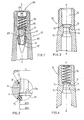
- Fig. 1 is a view of the sectioned valve;
- Fig. 2 is an enlarged view of the detail indicated in the outlined circle of Fig. 1;
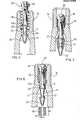
- Figs. 3 to 7 show subsequent steps of the assembly.
- As it is visible from Fig. 1, the valve comprises a limited number of parts: an
outside body 10 defining apassageway 16, aninside pin 20, a sealingmember 40 and, if desired, aspring 30. - A
constriction 11 is provided inside saidvalve body 10 substantially dividing said body in two: an outside part (shown above) and an inside part (shown below). The outside part provides a seat forspring 30 that leans against ashoulder 12; a flaredconic surface 13 is provided inbody 10 betweenshoulder 12 andconstriction 11. Theconic surface 13 is inclined with respect to valve's axis X-X of at angle comprised between 27 and 33°, in particular the angle may be 30°, - The inside part of
constriction 11 is provided with astep 14. Starting from thisstep 14 and going towards the valve's inside a furtherconic surface 15 is provided against which the top part of the sealingmember 40 leans. This surface will be calledsealing surface 15. - The sealing
member 40 at rest is a cylindrical tube having an internal diameter 41 (Fig. 6) which is about 25% of itslength 42. - A
pin 20 suitably shaped is housed inbody 10. Said pin is provided with ahead 26 to create a further abutment forspring 30.Pin 20 is also provided with aflange 23 forming ashelf 23a which facesstep 14 and abuts against it at the highest pressures. Deeper inside with respect toflange 23pin 20 is provided with a truncatedcone seat 21 for receiving the sealingmember 40, and pointedend 22 forming afurther abutment 24 for keeping sealingmember 40 in place. - The
flange 23's external diameter A (Fig. 2) is preferably about a 5 to 9% bigger than minimum diameter B of the body'sconstriction 11. - The separation D existing at rest with no pressure differential across the sealing surface 15 - is preferably within the range of 0,2mm-lmm.
- Moreover at rest the maximum external diameter C of the flared
conic surface 13 is preferably at least 5% greater than the external diameter A of theflange 23. - For the valve's assembly the following steps are foreseen:
- a)
valve body 10 is kept standing (Fig.3); - b)
spring 30 is inserted in the passageway 16 (Fig.4); - c)
pin 20 is inserted in the valve body inside spring 30 (Fig.5); - d)
pin 20 is given a sharp knock so thatflange 23 goes beyondconstriction 11; - e)
pin 20 is released and remains inserted becauseshelf 23a abuts against step 14 (Fig. 6); - f) sealing
member 40 is mounted from the bottom, whilepin 20 is lowered (Fig. 7); sealingmember 40 is seated oncone seat 21. - Pointed
end 24 is particularly useful during the assembly for guidingpin 20 inbody 10 and for facilitating the introduction of sealingmember 40. - When
pin 20 is positioned, the abutment existing betweenstep 14 andshelf 23a avoids the expulsion due to the action ofspring 30 when the sealingmember 40 is not present.
Claims (15)
Priority Applications (1)
| Application Number | Priority Date | Filing Date | Title |
|---|---|---|---|
| AT87830078T ATE65833T1 (en) | 1986-03-04 | 1987-03-03 | VALVE. |
Applications Claiming Priority (2)
| Application Number | Priority Date | Filing Date | Title |
|---|---|---|---|
| IT2112686U IT209132Z2 (en) | 1986-03-04 | 1986-03-04 | VALVE IMPROVEMENTS FOR TUBELESS TIRES. |
| IT2112686 | 1986-07-15 |
Publications (3)
| Publication Number | Publication Date |
|---|---|
| EP0237496A2 true EP0237496A2 (en) | 1987-09-16 |
| EP0237496A3 EP0237496A3 (en) | 1990-02-14 |
| EP0237496B1 EP0237496B1 (en) | 1991-07-31 |
Family
ID=11177119
Family Applications (2)
| Application Number | Title | Priority Date | Filing Date |
|---|---|---|---|
| EP19870830078 Expired - Lifetime EP0237496B1 (en) | 1986-03-04 | 1987-03-03 | Improvement in a valve |
| EP87901619A Pending EP0296163A1 (en) | 1986-03-04 | 1987-03-03 | Improvements in valves |
Family Applications After (1)
| Application Number | Title | Priority Date | Filing Date |
|---|---|---|---|
| EP87901619A Pending EP0296163A1 (en) | 1986-03-04 | 1987-03-03 | Improvements in valves |
Country Status (17)
| Country | Link |
|---|---|
| US (1) | US4836235A (en) |
| EP (2) | EP0237496B1 (en) |
| JP (1) | JPH01501887A (en) |
| KR (1) | KR880700908A (en) |
| CN (1) | CN1006657B (en) |
| AT (1) | ATE65833T1 (en) |
| AU (1) | AU597631B2 (en) |
| BR (1) | BR8707629A (en) |
| CA (1) | CA1266814A (en) |
| DE (1) | DE3771748D1 (en) |
| ES (1) | ES2023676B3 (en) |
| FR (1) | FR2600393B3 (en) |
| GR (1) | GR3002840T3 (en) |
| IT (1) | IT209132Z2 (en) |
| MX (1) | MX168640B (en) |
| WO (1) | WO1987005374A1 (en) |
| ZA (1) | ZA871520B (en) |
Cited By (1)
| Publication number | Priority date | Publication date | Assignee | Title |
|---|---|---|---|---|
| GB2238850A (en) * | 1987-02-02 | 1991-06-12 | Ziggity Systems Inc | Flow restrictor |
Families Citing this family (27)
| Publication number | Priority date | Publication date | Assignee | Title |
|---|---|---|---|---|
| US5253435A (en) | 1989-03-17 | 1993-10-19 | Nike, Inc. | Pressure-adjustable shoe bladder assembly |
| US5257470A (en) | 1989-03-17 | 1993-11-02 | Nike, Inc. | Shoe bladder system |
| CA2012141C (en) | 1989-03-17 | 1999-07-27 | Daniel R. Potter | Customized fit shoe and bladder and valve assembly therefor |
| CA2012140C (en) * | 1989-03-17 | 1999-01-26 | Daniel R. Potter | Athletic shoe with pressurized ankle collar |
| US5121771A (en) * | 1990-02-26 | 1992-06-16 | Scott Specialty Gases | Device for depressing a tire valve core in high pressure cylinders |
| US5113900A (en) * | 1991-01-30 | 1992-05-19 | Bridge Products, Inc. | Check valve with quick lock attachment feature |
| US5135025A (en) * | 1991-07-03 | 1992-08-04 | Mackal Glenn H | Articulated oral inflation valve |
| US5370527A (en) * | 1992-10-28 | 1994-12-06 | The Coleman Company, Inc. | Fuel tube for burner assembly with remote fuel tank |
| CN1038700C (en) * | 1994-01-11 | 1998-06-10 | 陈木兴 | Nonwoven fabric paper making method |
| AU771667B2 (en) | 1999-11-02 | 2004-04-01 | Fisher & Paykel Appliances Limited | A gas valve |
| US7328609B1 (en) * | 2004-10-29 | 2008-02-12 | National Semiconductor Corporation | Wireless pressure sensing Schrader valve |
| US7066442B2 (en) * | 2004-11-23 | 2006-06-27 | Rose Machine & Tool, Llc | Valve |
| JP4522953B2 (en) * | 2005-06-22 | 2010-08-11 | 太平洋工業株式会社 | Tire valve unit |
| FR2903752B1 (en) * | 2006-07-13 | 2008-12-05 | Michelin Soc Tech | PNEUMATIC VALVE. |
| JP4741444B2 (en) * | 2006-10-10 | 2011-08-03 | 太平洋工業株式会社 | Tire valve unit |
| US8210501B2 (en) * | 2009-06-12 | 2012-07-03 | Wuxi Deyang Industries Co., Ltd. | Inflation valve |
| DE202010000254U1 (en) * | 2010-02-24 | 2010-04-22 | Ptg Reifendruckregelsysteme Gmbh | tire valve |
| CN102367851B (en) * | 2011-10-14 | 2015-09-09 | 芜湖众发汽车制动系统有限公司 | The oil outlet mechanism of brake master cylinder |
| US9199518B2 (en) * | 2012-10-24 | 2015-12-01 | The Goodyear Tire & Rubber Company | Method of assemblying a segmented vein air pump in a tire |
| CN103899802B (en) * | 2014-04-22 | 2016-04-27 | 张筱秋 | The vertical one-way valve of screw joint evanohm four plate water conservancy diversion in a kind of |
| US9533533B2 (en) * | 2014-04-24 | 2017-01-03 | The Goodyear Tire & Rubber Company | Vein-style air pumping tube and tire system and method of assembly |
| DE202015105859U1 (en) | 2015-11-04 | 2017-02-07 | Ptg Reifendruckregelsysteme Gmbh | Wheel valve arrangement and tire pressure control system with at least one such wheel valve arrangement |
| JP6639876B2 (en) * | 2015-11-17 | 2020-02-05 | 株式会社不二工機 | Flow control valve |
| WO2020194471A1 (en) * | 2019-03-25 | 2020-10-01 | 太平洋工業株式会社 | Valve |
| US11085549B1 (en) * | 2019-03-26 | 2021-08-10 | Pacific Industrial Co., Ltd. | Valve |
| US11117426B1 (en) | 2021-03-24 | 2021-09-14 | Ptg Reifendruckregelsysteme Gmbh | Rotary transmission leadthrough as part of a tire pressure control system |
| CN114029380A (en) * | 2021-10-18 | 2022-02-11 | 乔克 | Stamping device for processing automobile stamping parts |
Citations (6)
| Publication number | Priority date | Publication date | Assignee | Title |
|---|---|---|---|---|
| BE672880A (en) * | 1965-02-26 | 1966-03-16 | ||
| GB1044423A (en) * | 1964-09-03 | 1966-09-28 | Eaton Yale & Towne | Valve extension |
| US3489166A (en) * | 1968-07-03 | 1970-01-13 | Scovill Manufacturing Co | Tire valve |
| FR2340493A1 (en) * | 1976-02-04 | 1977-09-02 | Beretta Dante | AIR CHAMBERS VALVE BODY OR OTHER |
| US4340080A (en) * | 1977-03-11 | 1982-07-20 | Compagnie Generale Des Etablissements Michelin | Inflation valve |
| EP0106966A1 (en) * | 1982-10-21 | 1984-05-02 | BRIDGEPORT BRASS S.p.A. | A valve for mounting on the rim of wheels provided with tubeless tyres |
Family Cites Families (14)
| Publication number | Priority date | Publication date | Assignee | Title |
|---|---|---|---|---|
| US1313554A (en) * | 1919-08-19 | Fbedekik nielsen | ||
| US2240129A (en) * | 1939-02-15 | 1941-04-29 | Bridgeport Brass Co | Valve |
| US2473591A (en) * | 1942-11-17 | 1949-06-21 | Dowty Equipment Ltd | Valve |
| DE802791C (en) * | 1948-12-03 | 1951-02-26 | Julius Schaefer | Valve for air hoses on bicycles and motorcycles |
| US2862515A (en) * | 1956-02-21 | 1958-12-02 | Scovill Manufacturing Co | Check valve |
| US3429330A (en) * | 1964-02-04 | 1969-02-25 | Halkey Roberts Corp | Mouthpiece for orally operated valve |
| US3396743A (en) * | 1965-12-16 | 1968-08-13 | Halkey Roberts Corp | Oral inflation valve |
| US4077456A (en) * | 1976-10-28 | 1978-03-07 | National Distillers And Chemical Corporation | Simplified valve for tubeless tire |
| FR2383374A1 (en) * | 1977-03-11 | 1978-10-06 | Michelin & Cie | Inflation valve for tubeless tyre - has elastically deformable retaining head for easy assembly in body |
| FR2417044A2 (en) * | 1978-02-08 | 1979-09-07 | Michelin & Cie | Inflation valve for tubeless tyre - has elastically deformable retaining head for easy assembly in body |
| US4176681A (en) * | 1977-09-07 | 1979-12-04 | Mackal Glenn H | Oral inflation valve |
| US4275756A (en) * | 1979-03-12 | 1981-06-30 | National Distillers And Chemical Corporation | Plastic valve core |
| US4506695A (en) * | 1983-04-04 | 1985-03-26 | Scovill Inc. | Plastic tire valve |
| US4739813A (en) * | 1984-04-17 | 1988-04-26 | Bridge Products, Inc. | Tubeless tire valve |
-
1986
- 1986-03-04 IT IT2112686U patent/IT209132Z2/en active
-
1987
- 1987-03-03 US US07/021,141 patent/US4836235A/en not_active Expired - Lifetime
- 1987-03-03 AT AT87830078T patent/ATE65833T1/en not_active IP Right Cessation
- 1987-03-03 DE DE8787830078T patent/DE3771748D1/en not_active Expired - Lifetime
- 1987-03-03 WO PCT/IT1987/000018 patent/WO1987005374A1/en not_active Application Discontinuation
- 1987-03-03 EP EP19870830078 patent/EP0237496B1/en not_active Expired - Lifetime
- 1987-03-03 EP EP87901619A patent/EP0296163A1/en active Pending
- 1987-03-03 ZA ZA871520A patent/ZA871520B/en unknown
- 1987-03-03 CA CA000531050A patent/CA1266814A/en not_active Expired - Fee Related
- 1987-03-03 FR FR8702865A patent/FR2600393B3/en not_active Expired
- 1987-03-03 AU AU70900/87A patent/AU597631B2/en not_active Ceased
- 1987-03-03 JP JP87501726A patent/JPH01501887A/en active Pending
- 1987-03-03 ES ES87830078T patent/ES2023676B3/en not_active Expired - Lifetime
- 1987-03-03 BR BR8707629A patent/BR8707629A/en not_active IP Right Cessation
- 1987-03-04 CN CN87104481A patent/CN1006657B/en not_active Expired
- 1987-03-04 MX MX005464A patent/MX168640B/en unknown
- 1987-11-04 KR KR1019870701008A patent/KR880700908A/en not_active Application Discontinuation
-
1991
- 1991-10-03 GR GR91401474T patent/GR3002840T3/en unknown
Patent Citations (6)
| Publication number | Priority date | Publication date | Assignee | Title |
|---|---|---|---|---|
| GB1044423A (en) * | 1964-09-03 | 1966-09-28 | Eaton Yale & Towne | Valve extension |
| BE672880A (en) * | 1965-02-26 | 1966-03-16 | ||
| US3489166A (en) * | 1968-07-03 | 1970-01-13 | Scovill Manufacturing Co | Tire valve |
| FR2340493A1 (en) * | 1976-02-04 | 1977-09-02 | Beretta Dante | AIR CHAMBERS VALVE BODY OR OTHER |
| US4340080A (en) * | 1977-03-11 | 1982-07-20 | Compagnie Generale Des Etablissements Michelin | Inflation valve |
| EP0106966A1 (en) * | 1982-10-21 | 1984-05-02 | BRIDGEPORT BRASS S.p.A. | A valve for mounting on the rim of wheels provided with tubeless tyres |
Cited By (2)
| Publication number | Priority date | Publication date | Assignee | Title |
|---|---|---|---|---|
| GB2238850A (en) * | 1987-02-02 | 1991-06-12 | Ziggity Systems Inc | Flow restrictor |
| GB2238850B (en) * | 1987-02-02 | 1991-10-09 | Ziggity Systems Inc | A fluid flow restrictor assembly |
Also Published As
| Publication number | Publication date |
|---|---|
| CN87104481A (en) | 1988-05-04 |
| MX168640B (en) | 1993-06-02 |
| IT209132Z2 (en) | 1988-09-12 |
| CA1266814A (en) | 1990-03-20 |
| AU7090087A (en) | 1987-09-28 |
| AU597631B2 (en) | 1990-06-07 |
| DE3771748D1 (en) | 1991-09-05 |
| EP0237496A3 (en) | 1990-02-14 |
| CN1006657B (en) | 1990-01-31 |
| WO1987005374A1 (en) | 1987-09-11 |
| ZA871520B (en) | 1988-02-24 |
| US4836235A (en) | 1989-06-06 |
| FR2600393A3 (en) | 1987-12-24 |
| JPH01501887A (en) | 1989-06-29 |
| ES2023676B3 (en) | 1992-02-01 |
| EP0237496B1 (en) | 1991-07-31 |
| ATE65833T1 (en) | 1991-08-15 |
| EP0296163A1 (en) | 1988-12-28 |
| IT8621126V0 (en) | 1986-03-04 |
| KR880700908A (en) | 1988-04-13 |
| FR2600393B3 (en) | 1988-08-05 |
| GR3002840T3 (en) | 1993-01-25 |
| BR8707629A (en) | 1989-03-14 |
Similar Documents
| Publication | Publication Date | Title |
|---|---|---|
| EP0237496A2 (en) | Improvement in a valve | |
| US4919457A (en) | Releasable plug connection | |
| US4978341A (en) | Introducer valve for a catheter arrangement | |
| US3472457A (en) | Aerosol tip and insert assembly | |
| US4337873A (en) | Fuel cap with poppet type valves | |
| EP0754281B1 (en) | Valve assembly | |
| US5104131A (en) | Arrangement for sealing a reciprocating rod | |
| US4706705A (en) | Check valve | |
| US4060219A (en) | Quick disconnect coupler and safety check valve | |
| US4590957A (en) | Pressure relief device | |
| US20040035571A1 (en) | Water, oil and gas well recovery system | |
| US6308869B1 (en) | Keg and keg fitting for dispensing liquids under pressure | |
| US4723670A (en) | Pump closure for carbonated beverage container | |
| GB2191271A (en) | Improvements in or relating to check valves | |
| EP0112127A3 (en) | Propellant augmented pressurized gas dispensing device and manufacturing method therefor | |
| EP0047055B1 (en) | Valves | |
| EP0001350A1 (en) | Relief valve | |
| CA2328742A1 (en) | Two-way check valve | |
| GB2043830A (en) | Filling pressurised fluid piston and cylinder devices | |
| EP0686988A1 (en) | Thermal cutoff | |
| US3949780A (en) | Two piece check valve | |
| US3228419A (en) | Relief valve | |
| US20160061341A1 (en) | Valve device with enhanced reseat capabilities | |
| US5038952A (en) | Closure assembly for pressurized plastic beverage container | |
| US3918482A (en) | Relief valve core |
Legal Events
| Date | Code | Title | Description |
|---|---|---|---|
| PUAI | Public reference made under article 153(3) epc to a published international application that has entered the european phase |
Free format text: ORIGINAL CODE: 0009012 |
|
| AK | Designated contracting states |
Kind code of ref document: A2 Designated state(s): ES GR |
|
| PUAL | Search report despatched |
Free format text: ORIGINAL CODE: 0009013 |
|
| AK | Designated contracting states |
Kind code of ref document: A3 Designated state(s): ES GR |
|
| RAP1 | Party data changed (applicant data changed or rights of an application transferred) |
Owner name: BRIDGE PRODUCTS, INC. |
|
| 17P | Request for examination filed |
Effective date: 19900310 |
|
| XX | Miscellaneous (additional remarks) |
Free format text: VERBUNDEN MIT 87901619.4/0296163 (EUROPAEISCHE ANMELDENUMMER/VEROEFFENTLICHUNGSNUMMER) DURCH ENTSCHEIDUNG VOM 18.07.90. |
|
| 17Q | First examination report despatched |
Effective date: 19900820 |
|
| GRAA | (expected) grant |
Free format text: ORIGINAL CODE: 0009210 |
|
| AK | Designated contracting states |
Kind code of ref document: B1 Designated state(s): AT BE CH DE ES FR GB GR IT LI LU NL SE |
|
| REF | Corresponds to: |
Ref document number: 65833 Country of ref document: AT Date of ref document: 19910815 Kind code of ref document: T |
|
| XX | Miscellaneous (additional remarks) |
Free format text: VERBUNDEN MIT 87901619.4/0296163 (EUROPAEISCHE ANMELDENUMMER/VEROEFFENTLICHUNGSNUMMER) DURCH ENTSCHEIDUNG VOM 18.07.90. |
|
| ITF | It: translation for a ep patent filed |
Owner name: DR. ING. A. RACHELI & C. |
|
| REF | Corresponds to: |
Ref document number: 3771748 Country of ref document: DE Date of ref document: 19910905 |
|
| ET | Fr: translation filed | ||
| REG | Reference to a national code |
Ref country code: ES Ref legal event code: FG2A Ref document number: 2023676 Country of ref document: ES Kind code of ref document: B3 |
|
| PGFP | Annual fee paid to national office [announced via postgrant information from national office to epo] |
Ref country code: GB Payment date: 19920221 Year of fee payment: 6 |
|
| PGFP | Annual fee paid to national office [announced via postgrant information from national office to epo] |
Ref country code: ES Payment date: 19920302 Year of fee payment: 6 |
|
| PGFP | Annual fee paid to national office [announced via postgrant information from national office to epo] |
Ref country code: FR Payment date: 19920310 Year of fee payment: 6 |
|
| PGFP | Annual fee paid to national office [announced via postgrant information from national office to epo] |
Ref country code: AT Payment date: 19920311 Year of fee payment: 6 |
|
| PGFP | Annual fee paid to national office [announced via postgrant information from national office to epo] |
Ref country code: CH Payment date: 19920316 Year of fee payment: 6 |
|
| PGFP | Annual fee paid to national office [announced via postgrant information from national office to epo] |
Ref country code: SE Payment date: 19920319 Year of fee payment: 6 Ref country code: LU Payment date: 19920319 Year of fee payment: 6 |
|
| PGFP | Annual fee paid to national office [announced via postgrant information from national office to epo] |
Ref country code: GR Payment date: 19920327 Year of fee payment: 6 |
|
| PGFP | Annual fee paid to national office [announced via postgrant information from national office to epo] |
Ref country code: NL Payment date: 19920331 Year of fee payment: 6 Ref country code: DE Payment date: 19920331 Year of fee payment: 6 |
|
| PGFP | Annual fee paid to national office [announced via postgrant information from national office to epo] |
Ref country code: BE Payment date: 19920512 Year of fee payment: 6 |
|
| PLBE | No opposition filed within time limit |
Free format text: ORIGINAL CODE: 0009261 |
|
| STAA | Information on the status of an ep patent application or granted ep patent |
Free format text: STATUS: NO OPPOSITION FILED WITHIN TIME LIMIT |
|
| 26N | No opposition filed | ||
| EPTA | Lu: last paid annual fee | ||
| REG | Reference to a national code |
Ref country code: GR Ref legal event code: FG4A Free format text: 3002840 |
|
| PG25 | Lapsed in a contracting state [announced via postgrant information from national office to epo] |
Ref country code: LU Free format text: LAPSE BECAUSE OF NON-PAYMENT OF DUE FEES Effective date: 19930303 Ref country code: GB Effective date: 19930303 Ref country code: AT Effective date: 19930303 |
|
| PG25 | Lapsed in a contracting state [announced via postgrant information from national office to epo] |
Ref country code: SE Effective date: 19930304 Ref country code: ES Free format text: LAPSE BECAUSE OF NON-PAYMENT OF DUE FEES Effective date: 19930304 |
|
| PG25 | Lapsed in a contracting state [announced via postgrant information from national office to epo] |
Ref country code: LI Effective date: 19930331 Ref country code: CH Effective date: 19930331 Ref country code: BE Effective date: 19930331 |
|
| BERE | Be: lapsed |
Owner name: BRIDGE PRODUCTS INC. Effective date: 19930331 |
|
| PG25 | Lapsed in a contracting state [announced via postgrant information from national office to epo] |
Ref country code: GR Free format text: THE PATENT HAS BEEN ANNULLED BY A DECISION OF A NATIONAL AUTHORITY Effective date: 19930930 |
|
| PG25 | Lapsed in a contracting state [announced via postgrant information from national office to epo] |
Ref country code: NL Effective date: 19931001 |
|
| GBPC | Gb: european patent ceased through non-payment of renewal fee |
Effective date: 19930303 |
|
| NLV4 | Nl: lapsed or anulled due to non-payment of the annual fee | ||
| PG25 | Lapsed in a contracting state [announced via postgrant information from national office to epo] |
Ref country code: FR Effective date: 19931130 |
|
| REG | Reference to a national code |
Ref country code: CH Ref legal event code: PL |
|
| PG25 | Lapsed in a contracting state [announced via postgrant information from national office to epo] |
Ref country code: DE Effective date: 19931201 |
|
| REG | Reference to a national code |
Ref country code: FR Ref legal event code: ST |
|
| REG | Reference to a national code |
Ref country code: GR Ref legal event code: MM2A Free format text: 3002840 |
|
| EUG | Se: european patent has lapsed |
Ref document number: 87830078.9 Effective date: 19931008 |
|
| REG | Reference to a national code |
Ref country code: ES Ref legal event code: FD2A Effective date: 19990503 |
|
| PG25 | Lapsed in a contracting state [announced via postgrant information from national office to epo] |
Ref country code: IT Free format text: LAPSE BECAUSE OF NON-PAYMENT OF DUE FEES;WARNING: LAPSES OF ITALIAN PATENTS WITH EFFECTIVE DATE BEFORE 2007 MAY HAVE OCCURRED AT ANY TIME BEFORE 2007. THE CORRECT EFFECTIVE DATE MAY BE DIFFERENT FROM THE ONE RECORDED. Effective date: 20050303 |