EP0237423B1 - Locked connector - Google Patents
Locked connector Download PDFInfo
- Publication number
- EP0237423B1 EP0237423B1 EP87400492A EP87400492A EP0237423B1 EP 0237423 B1 EP0237423 B1 EP 0237423B1 EP 87400492 A EP87400492 A EP 87400492A EP 87400492 A EP87400492 A EP 87400492A EP 0237423 B1 EP0237423 B1 EP 0237423B1
- Authority
- EP
- European Patent Office
- Prior art keywords
- detent
- plug
- ring
- plug shell
- shell
- Prior art date
- Legal status (The legal status is an assumption and is not a legal conclusion. Google has not performed a legal analysis and makes no representation as to the accuracy of the status listed.)
- Expired
Links
- 230000008878 coupling Effects 0.000 claims description 40
- 238000010168 coupling process Methods 0.000 claims description 40
- 238000005859 coupling reaction Methods 0.000 claims description 40
- 239000013307 optical fiber Substances 0.000 claims description 3
- 230000003247 decreasing effect Effects 0.000 claims description 2
- 230000007246 mechanism Effects 0.000 claims description 2
- 238000006243 chemical reaction Methods 0.000 description 4
- 238000004519 manufacturing process Methods 0.000 description 3
- 230000004048 modification Effects 0.000 description 3
- 238000012986 modification Methods 0.000 description 3
- 230000000994 depressogenic effect Effects 0.000 description 2
- 229920001971 elastomer Polymers 0.000 description 2
- 238000003780 insertion Methods 0.000 description 2
- 230000037431 insertion Effects 0.000 description 2
- 230000009191 jumping Effects 0.000 description 2
- 230000013011 mating Effects 0.000 description 2
- 238000005266 casting Methods 0.000 description 1
- 230000008859 change Effects 0.000 description 1
- 230000000694 effects Effects 0.000 description 1
- 239000000806 elastomer Substances 0.000 description 1
- 238000000034 method Methods 0.000 description 1
- 238000000465 moulding Methods 0.000 description 1
- 238000009740 moulding (composite fabrication) Methods 0.000 description 1
- 230000003014 reinforcing effect Effects 0.000 description 1
Images








Classifications
-
- H—ELECTRICITY
- H01—ELECTRIC ELEMENTS
- H01R—ELECTRICALLY-CONDUCTIVE CONNECTIONS; STRUCTURAL ASSOCIATIONS OF A PLURALITY OF MUTUALLY-INSULATED ELECTRICAL CONNECTING ELEMENTS; COUPLING DEVICES; CURRENT COLLECTORS
- H01R13/00—Details of coupling devices of the kinds covered by groups H01R12/70 or H01R24/00 - H01R33/00
- H01R13/62—Means for facilitating engagement or disengagement of coupling parts or for holding them in engagement
- H01R13/623—Casing or ring with helicoidal groove
-
- H—ELECTRICITY
- H01—ELECTRIC ELEMENTS
- H01R—ELECTRICALLY-CONDUCTIVE CONNECTIONS; STRUCTURAL ASSOCIATIONS OF A PLURALITY OF MUTUALLY-INSULATED ELECTRICAL CONNECTING ELEMENTS; COUPLING DEVICES; CURRENT COLLECTORS
- H01R13/00—Details of coupling devices of the kinds covered by groups H01R12/70 or H01R24/00 - H01R33/00
- H01R13/62—Means for facilitating engagement or disengagement of coupling parts or for holding them in engagement
- H01R13/622—Screw-ring or screw-casing
Definitions
- This invention relates to a connector used as an electric or optical fiber connector adapted to be prevented from disconnection due to mechanical vibration and change in temperature or pressure, and more particularly to an improved connector which is easily detachable by a simple operation and inexpensive to manufacture with less number of parts and is high in reliability.
- the connector disclosed in the Japanese Patent Application Publication No. 8,033/84 includes receptacle means having a receptacle shell, a plug shell having connecting nuts threadedly engaged the plug shell, plug means having a connecting ring housing keyed to the connecting nuts, electric contact elements adapted to do electric connection and disconnection in the receptacle and plug shells according to instruction, and fixing means on the connecting ring housing and the receptacle shell for detachably holding the electric contact elements in engaged positions.
- the connector further comprises display means for visually indicating the completely engaged and fixed positional relation between the receptacle means and the plug means.
- the display means comprises an inner annular groove formed in the connecting ring housing, a circular arc detent member having an elasticity located in the inner annular groove and means for governing relative rotating movement between the plug shell and the detent member having ends facing radially outwardly.
- the inner annular groove of the connecting ring housing includes sets of recesses spaced and located radially outwardly for selectively receiving the ends of the detent member.
- the characterizing feature lies in that when the housing is forced to be rotated, the ends of the circular arc detent member are pushed out of the first set of the recesses and into the second set of the recesses to generate the sound, thereby causing the engagement of the receptacle and plug means to completely fix the housing.
- these many parts include those not suitable for being worked using molds as in press-forming, casting, molding and the like. This fact makes the connector expensive and limits applications of the connector.
- the plug shell and connecting nuts have screw threads threadedly engaged with each other, which are unable to be formed by press-forming and other working using molds.
- the recesses for receiving the ends of the circular arc detent member facing radially outwardly are not formed by press-forming or other working using molds.
- the connector of the prior art therefore, involves a great problem in working the parts.
- GB-A-2023358 and FR-A-1168745 relate both to a connector having a flange portion while in said invention the connector has a circular flange surface.
- GB-A-2 023 358 discloses a locked connector for use in electric connectors or in optical fiber connectors, including receptacle means having a receptacle shell, coupling means engaging the receptacle means with relative rotations, plug shell means having a plug shell engaging the receptacle shell with relative movements in their axial directions but against relative rotation, back-up means permitting said coupling means and said plug shell means to rotatably engage with each other, and detent means for holding said receptacle means and said plug shell means in their fitted position and permitting said receptacle means and said plug shell means to disengage from the fitted position by rotating said coupling means relative to said plug shell means with a force, said detent means comprising a detent ring encircling said plug shell means, said detent ring having means for rotating together with said coupling means to form a detent mechanism in connection with said plug shell, and spring means for urging said detent ring toward said plug shell.
- the locked connector is further characterized in that said detent ring is provided with detent projections extending in an axial direction of the detent ring; said plug shell including a plug flange encircling the plug shell, said plug flange being formed with a plurality of detent recesses for receiving said detent projections of said detent ring to form said detent means; said plug flange being provided with surfaces in opposition to said detent ring, said surfaces each having a mid-portion between said adjacent detent recesses and having a progressively decreased thickness from said mid-portion to the adjacent detent recesses to form a plurality of circular surfaces about the circumference of the plug flange, said detent recesses located at the bottoms of said circular arc surfaces.
- the detent ring comprises detent projections extending in an axial direction of the detent ring
- the plug shell comprises a plug flange encircling the plug shell, the plug flange being formed with detent recesses for receiving the detent projections of the detent ring to form the detent means.
- surfaces of the plug flange in opposition to the detent ring progressively increase their thickness from one detent recess to the adjacent detent recess to form circular arc surfaces in circular directions of the plug flange and the detent recesses are located at bottoms of the circular arc surfaces.
- the detent projections of the detent ring are two and located in diametrically opposed positions, and the detent recesses of the plug flange are four and located at four positions equally spaced on the plug flange.
- the detent ring is bent to form an angle about a line connecting the two detent projections to have a springiness, thereby integrally forming the detent ring and the spring means.
- a receptacle shell 10 into which is inserted an insert (not shown) as first connector means having a number of socket contacts.
- the receptacle shell 10 comprises three lands 11 for fixing a mating member later described, a master key way 12, four key ways 13 and a mounting flange 14 formed with mounting apertures 15.
- Fig. 1 illustrates a plug shell 50 as the mating member into which is inserted an insert (not shown) as second connector means having a number of pin contacts.
- the plug shell 50 comprises a master key 51 adapted to be fitted in the master key way 12, four keys 52 adapted to be fitted in the four key ways 13 of the receptacle shell 10, and a plug flange 55 encircling the plug shell 50.
- the plug flange 55 is formed with four detent recesses 53 which are in parallel with an axis of the plug shell 50 and depressed from a side surface of the plug flange 55 and are equally spaced on a circumference of the plug flange 55.
- the plug flange 55 is further formed with two rotation stoppers 54 extending forward from a front side of the plug flange 55.
- a coupling 30 (which is cylindrical but is shown in Fig. 1 after removal of its half for the sake of clarity) is in cooperation with the plug shell 50 to enable it to be detachable from the receptacle shell 10.
- the coupling 30 comprises, in its inner surface, tapered lands 31 each in the form of a circular arc having a tapered portion 32, two detent key ways 33 provided in an inner surface of a rear portion of the coupling 30 in parallel with an axis of the coupling 30, rotation protrusions 34 formed in the inner surface of the coupling and extending rearward in parallel with the axis of the coupling 30, and a retainer ring groove 35 formed behind the rotation protrusions 34 in the inner surface of the coupling 30.
- a detent spring ring 70 comprises two detent projections 71 extending in parallel with an axis of the detent spring ring 70 in a manner dividing the detent spring ring 70 into two equal parts, and two detent keys 72 located between the two detent projections 71 and extending radially outwardly of the detent spring ring 70.
- a back-up ring 81 serves to hold the detent spring ring 70 on the rear side and is prevented from jumping out of the plug shell 50 with the aid of a retainer ring 85 fitted in the retainer ring groove 35.
- Fig. 2a a partial sectional view illustrating the condition before fitting, the receptacle shell 10 incorporates therein an insert 102 having a number of socket contacts 106 and the plug shell 50 incorporates therein an insert 101 having a number of pin contacts 105.
- Reference numeral 82 denotes a gasket made of an elastomer such as an annular rubber.
- Reference numeral 99 illustrates a panel to which the mounting flange 14 is fixed by means of the mounting apertures 15 (Fig. 1).
- Fig. 2b is a sectional view taken along a line IIb-IIb
- Fig. 2c is a sectional view taken along a line IIc-IIc in Fig. 2a.
- Fig. 2c illustrates one of the detent projections 71 of the detent spring ring 70 fitted in the first pair of detent recesses 53. It is understood from Fig. 2c that the detent spring ring 70 is restrained by the back-up ring 81 which is in turn prevented by the retainer ring 85 from jumping out (toward the right in Fig. 2c) of the coupling 30. It is further understood from Fig. 2d which is a sectional view taken along a line IId-IId in Fig. 2c that the detent keys 72 are fitted in the detent key ways 33 formed in the inside of the coupling 30 so that when the coupling 30 is forced to rotate, the detent spring ring 70 is rotated together therewith.
- Fig. 3a is a sectional view illustrating the half fitted condition. A relation between the fixing lands 11 and the tapered lands 31 shown in phantom lines in Fig. 3a should be noticed.
- the coupling 30 is rotated, the tapered lands 31 are lowered downward viewed in Fig. 3a so that upper left-hand corners of the lands 11 viewed in this drawing slide on the tapered portions and arrive at tapered land surface portions 36 contiguous to the tapered portions.
- the coupling 30 and the plug shell fixed thereto are advanced to the left in the drawing to accomplish a complete fitting of the receptacle shell 10 and the plug shell 50.
- Fig. 3b which is a sectional view taken along a line IIIb-IIIb in Fig.
- the master key 51 has been fitted in the master key groove 12 and the four keys 52 have been fitted in the key ways 13, so that even if the coupling 30 is forced to rotate in the direction 121 or in a direction opposite thereto, the plug shell 50 is not rotated relative to the coupling 30.
- the fixing lands 11 and the tapered lands 31 do not overlap in their axial directions, so that the plug shell 50 can be inserted into or removed from the receptacle shell 10.
- Fig. 4a is a partial sectional view illustrating the fitted condition wherein the coupling 30 has been rotated in a clockwise direction viewed from a right side of Fig. 4a or from a rear side of the plug shell 50.
- the tapered portions 32 of the tapered lands 31 in phantom lines are urged against the fixing lands 11 in phantom lines to cause the plug shell 50 to move toward the left viewed in Fig. 4a.
- the tapered land surface portions 36 of the tapered lands 31 are brought into contact with the fixing lands 11 to complete the movement of the plug shell 50 in the left direction viewed in Fig. 4a.
- Fig. 4b is a sectional view taken along a line IVb-IVb in Fig. 4a, illustrating a relative position between the fixing lands 11 and the tapered lands 31.
- parts 11d of the fixing lands 11 in phantom lines engage the tapered lands 31 to prevent the plug shell 50 from being removed.
- a force required to insert the plug shell 50 into the receptacle shell 10 is not large on the way from the condition before fitted shown in Figs. 2a, 2b, 2c and 2d to the half fitted condition shown in Figs. 3a and 3b.
- a fairly large force is required to bring the half fitted condition into the fitted condition shown in Figs. 4a and 4b.
- such a large force is obtained by the relative rotating movement between the tapered portions 32 and the fixing lands 11, so that the coupling is rotated only by a slight force.
- the procedure above described may be effected in a reverse order. Namely, the plug shell 50 is rotated through 90° in a counterclockwise direction viewed from the rear side of the plug shell 50 in Fig. 4a to bring the condition shown in this drawing into the half fitted condition in Figs. 3a and 3b. At the beginning of the rotation of the plug shell 50, a somewhat large force is needed in order to remove the detent projections 71 from the second pair of detent recesses 53. After the plug shell 50 has been rotated through 90°, the detent projections 71 are fitted in the first pair of detent recesses 53 as shown in Fig. 3a to generate a sound which is so-called "reaction". Under this condition, the receptacle shell 10 and the coupling 30 do not have overlapped portions, so that the plug shell can be removed from the receptacle shell 10.
- the master key 51 and the master key groove 12 have been formed in the plug shell 50 and the receptacle shell 10 respectively, this is only by way of example, and the master key 51 could be formed in the receptacle shell 10 and the master key groove 12 could be formed in the coupling 50.
- the keys 52 and the key ways 13 positions of the fixing lands 11 and the tapered lands 31 may be replaced.
- tapered portions may be further provided on the fixing lands.
- the gasket 82 may be provided on the inner surface of the receptacle shell 50 in opposition to a front end of the plug shell 50, instead of providing the gasket 81 on the plug shell 50.
- Figs. 5a-5d illustrate modifications of the embodiment above described.
- Circular arc-shaped recesses 53R are formed in a plug flange 55 of a plug shell 50 as shown in Fig. 5a instead of the recesses 53 shown in Fig. 2c.
- cylindrical rotatable detent bushes 73 may be supported by detent bush pins 74 provided on a detent spring ring 70 as shown in Fig. 5b.
- they may be modified to have detent projections 57 and detent recesses 75 as shown in Fig. 5c.
- FIG. 1 has been shown as the shape forming an angle about a line connecting the two detent projections 71 to have a springiness in itself (Fig. 2c), it may consist of a flat detent spring ring 70b and a waved spring ring 76 reinforcing the flat ring 70b. Instead of the waved spring ring 76, a coil spring may be used.
- the detent projections 71 extend in parallel with an axis of the detent spring rings, the detent recesses are depressed in the axial direction, so that maximum outer diameters of the plug shell 50 and the coupling 30 can be small.
- Fig. 6 illustrates a second embodiment of the invention in an exploded perspective view.
- a plug flange 55 is formed with four detent recesses 53 similar to those in the first embodiment and is further formed with four circular arc surfaces 56 between the four detent recesses 53.
- the shape of the circular arc surfaces 56 is clearly shown in Fig. 7 illustrating detent projections 71 of a detent spring ring 70 fitted in the first pair of detent recesses 53.
- the portions of the plug flange 55 between the detent recesses 53 progressively increase their thickness from one recess 53 to the adjacent recess 53 to form circular arc surfaces 56 in circular directions of the flange 55.
- Fig. 8 is a partial sectional view illustrating the fitted condition of a receptacle shell 10 and a plug shell 50.
- detent projections 71 in phantom lines slide on the circular arc surfaces 56 to be fitted in the second pair of detent recesses 53 so as to generate a sound.
- a force required to bring a half fitted condition into the fitted condition can be reduced as in the first embodiment.
- Such a force is obtained by a relative rotating movement between tapered portions 32 and fixing lands 11 and further the detent projections 71 slide on inclined surfaces of the circular arc surfaces 56 and fall into the detent recesses 53 at bottoms of the inclined surfaces, so that the coupling is rotated only by a slight force.
- mountain-like surfaces may be used, which consists of two inclined straight surfaces.
- Fig. 9 illustrates a third embodiment of the invention in an exploded perspective view.
- rotation lands 31 on a coupling 30 do not have tapered portions and are in the form of a circular arc extending inwardly and circumferentially. Furthermore, rotation protrusions 34 are formed extending inwardly so as to abut against rotation stoppers 54 of the plug shell 50 to prevent it from rotating.
- two detent projections 71 of a detent spring ring 70 extend on the right side viewed in this drawing.
- the plug shell 50 is formed with four detent recesses 53 opening toward the receptacle shell and with two rotation stoppers 54 located inwardly of a plug flange 55 and extending in an axial direction of the plug shell 50 toward the receptacle shell 10.
- a retainer ring 85 as back-up means is adapted to be fitted in a retainer ring groove 35 in the coupling 30 to prevent the plug shell 50 from removing toward on a rear side or the right side viewed in Fig. 9.
- Figs. 10a-10d correspond to Fig. 2a-2d of the first embodiment above described.
- the detent spring ring 70 is embraced between the coupling 30 and the plug shell 50, and the plug shell 50 is prevented from removing toward the right viewed in the drawing with the aid of the retainer ring 85 fitted in the retainer ring groove 35 of the coupling 30.
- tapered portions may be further provided on the rotation lands 31.
- Fig. 13 illustrates a modification of the detent spring ring denoted by 70b corresponding to that shown in Fig. 5d.
- a waved spring ring 76 is arranged on the left side of the detent spring ring 70b or on the side of the receptacle shell 10.
- portions of the plug flange 55 between the detent recesses 53 may be formed in circular arc surfaces as in the second embodiment to facilitate the sliding of the detent projections 71 thereon, thereby making more clear the reaction of insertion and removal and making small the rotating force required therefor (Fig. 14).
- the present invention can provide an improved connector which is prevented from disconnection due to vibration or the like and is easy and inexpensive to manufacture with less number of parts to bring a significant effect for the industry.
Landscapes
- Details Of Connecting Devices For Male And Female Coupling (AREA)
Description
- This invention relates to a connector used as an electric or optical fiber connector adapted to be prevented from disconnection due to mechanical vibration and change in temperature or pressure, and more particularly to an improved connector which is easily detachable by a simple operation and inexpensive to manufacture with less number of parts and is high in reliability.
- It is required to have high reliability for connectors used under greatly variable conditions and subjected to mechanical vibration as when used in vehicles, aircrafts, robots and the like.
- With these connectors, in general, a plug is inserted into a receptacle and clamped to the receptacle by set screws with the aid of a coupling rotatable about an axis of the connector. However, no matter how the clamping by set screws is strongly effected, there is a tendency for the clamping to be loosened when subjected to vibration, resulting finally into contact failure of the connector.
- Connectors intended to eliminate such disadvantages of the prior art have been disclosed in Japanese Patent Application Publications Nos. 8,033/84 and 8,034/84 and Japanese Laid-open Patent Application No. 13,679/84. For example, the connector disclosed in the Japanese Patent Application Publication No. 8,033/84 includes receptacle means having a receptacle shell, a plug shell having connecting nuts threadedly engaged the plug shell, plug means having a connecting ring housing keyed to the connecting nuts, electric contact elements adapted to do electric connection and disconnection in the receptacle and plug shells according to instruction, and fixing means on the connecting ring housing and the receptacle shell for detachably holding the electric contact elements in engaged positions. The connector further comprises display means for visually indicating the completely engaged and fixed positional relation between the receptacle means and the plug means. The display means comprises an inner annular groove formed in the connecting ring housing, a circular arc detent member having an elasticity located in the inner annular groove and means for governing relative rotating movement between the plug shell and the detent member having ends facing radially outwardly. The inner annular groove of the connecting ring housing includes sets of recesses spaced and located radially outwardly for selectively receiving the ends of the detent member. With this arrangement, when the housing is rotated into the completely engaged and fixed position, the ends of the detent member are forced out of a first set of the recesses into a second set of the recesses to generate a sound.
- With this connector of the prior art, the characterizing feature lies in that when the housing is forced to be rotated, the ends of the circular arc detent member are pushed out of the first set of the recesses and into the second set of the recesses to generate the sound, thereby causing the engagement of the receptacle and plug means to completely fix the housing.
- In this prior art, however, there is a problem in a great number of the parts for constituting the connector as can be seen from the claim, the detailed explanation and drawings of the Japanese Patent Application Publication No. 8,033/84.
- Moreover, these many parts include those not suitable for being worked using molds as in press-forming, casting, molding and the like. This fact makes the connector expensive and limits applications of the connector.
- For example, the plug shell and connecting nuts have screw threads threadedly engaged with each other, which are unable to be formed by press-forming and other working using molds. Moreover, the recesses for receiving the ends of the circular arc detent member facing radially outwardly are not formed by press-forming or other working using molds. The connector of the prior art, therefore, involves a great problem in working the parts.
- GB-A-2023358 and FR-A-1168745 relate both to a connector having a flange portion while in said invention the connector has a circular flange surface.
- GB-A-2 023 358 discloses a locked connector for use in electric connectors or in optical fiber connectors, including receptacle means having a receptacle shell, coupling means engaging the receptacle means with relative rotations, plug shell means having a plug shell engaging the receptacle shell with relative movements in their axial directions but against relative rotation, back-up means permitting said coupling means and said plug shell means to rotatably engage with each other, and detent means for holding said receptacle means and said plug shell means in their fitted position and permitting said receptacle means and said plug shell means to disengage from the fitted position by rotating said coupling means relative to said plug shell means with a force, said detent means comprising a detent ring encircling said plug shell means, said detent ring having means for rotating together with said coupling means to form a detent mechanism in connection with said plug shell, and spring means for urging said detent ring toward said plug shell.
- It is a principal object of the invention to provide an improved locked connector which eliminates all the disadvantages of the prior art and which is easy and inexpensive to manufacture with less number of parts, capable of indicating a complete connection of the connector by a sound and preventing from disconnection due to vibration or the like.
- In order to achieve this object, according with this invention, the locked connector is further characterized in that said detent ring is provided with detent projections extending in an axial direction of the detent ring; said plug shell including a plug flange encircling the plug shell, said plug flange being formed with a plurality of detent recesses for receiving said detent projections of said detent ring to form said detent means; said plug flange being provided with surfaces in opposition to said detent ring, said surfaces each having a mid-portion between said adjacent detent recesses and having a progressively decreased thickness from said mid-portion to the adjacent detent recesses to form a plurality of circular surfaces about the circumference of the plug flange, said detent recesses located at the bottoms of said circular arc surfaces.
- In a preferred embodiment of the invention, the detent ring comprises detent projections extending in an axial direction of the detent ring, and the plug shell comprises a plug flange encircling the plug shell, the plug flange being formed with detent recesses for receiving the detent projections of the detent ring to form the detent means.
- In another embodiment, surfaces of the plug flange in opposition to the detent ring progressively increase their thickness from one detent recess to the adjacent detent recess to form circular arc surfaces in circular directions of the plug flange and the detent recesses are located at bottoms of the circular arc surfaces.
- In a further embodiment, the detent projections of the detent ring are two and located in diametrically opposed positions, and the detent recesses of the plug flange are four and located at four positions equally spaced on the plug flange.
- In a preferred embodiment, the detent ring is bent to form an angle about a line connecting the two detent projections to have a springiness, thereby integrally forming the detent ring and the spring means.
- With this arrangement, a complete connection of the connector is detached by a sound generated when the detent projections fall into the detent recesses. As a force is required to remove the detent projections from the detent recesses, any unintentional disconnection of the connector due to vibration or the like is prevented.
- The invention will be more fully understood by referring to the following detailed specification and claims taken in connection with the appended drawings.
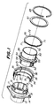
- Fig. 1 is an exploded perspective view of a first embodiment of the invention;
- Fig. 2a is a partial sectional view of the connector before fitting;
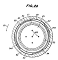
- Fig. 2b is a sectional view taken along the line IIb-IIb in Fig. 2a;
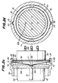
- Fig. 2c is a sectional view taken along the line IIc-IIc in Fig. 2a;
- Fig. 2d is a sectional view taken along the line IId-IId in Fig. 2c;
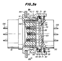
- Fig. 3a is a partial sectional view illustrating a half fitted condition of the connector;
- Fig. 3b is a sectional view taken along the line IIIb-IIIb in Fig. 3a;
- Fig. 4a is a sectional view illustrating a completely fitted condition of the connector;
- Fig. 4b is a sectional view taken along the line IVb-IVb in Fig. 4a;
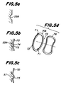
- Figs. 5a-5d illustrate modifications of the detent spring ring used in the connector;
- Fig. 6 is an exploded perspective view of a second embodiment of the invention;
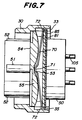
- Fig. 7 is a sectional view of the connector shown in Fig. 6 before fitting, corresponding to Fig. 2c;
- Fig. 8 is a partial sectional view of the connection illustrating a completely fitted condition of the connector;
- Fig. 9 is an exploded perspective view of a third embodiment of the invention;
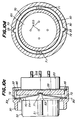
- Fig. 10a is a partial sectional view of the connector before fitting;
- Fig. 10b is a sectional view taken along the line Xb-Xb in Fig. 10a;
- Fig. 10c is a sectional view taken along the line Xc-Xc in Fig. 10a;
- Fig. 10d is a sectional view taken along the line Xd-Xd in Fig. 10c;
- Fig. 11 is a partial sectional view illustrating a half fitted condition of the connector;
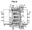
- Fig. 12 is a partial sectional view illustrating a completely fitted condition of the connector;
- Fig. 13 is a perspective view of a modified detent spring ring; and
- Fig. 14 is a partial sectional view illustrating a further embodiments of the Invention.
- Referring to Fig. 1 illustrating one embodiment of the invention, there is shown a
receptacle shell 10 into which is inserted an insert (not shown) as first connector means having a number of socket contacts. Thereceptacle shell 10 comprises threelands 11 for fixing a mating member later described, a masterkey way 12, fourkey ways 13 and a mountingflange 14 formed with mountingapertures 15. - Fig. 1 illustrates a
plug shell 50 as the mating member into which is inserted an insert (not shown) as second connector means having a number of pin contacts. Theplug shell 50 comprises amaster key 51 adapted to be fitted in the masterkey way 12, fourkeys 52 adapted to be fitted in the fourkey ways 13 of thereceptacle shell 10, and aplug flange 55 encircling theplug shell 50. Theplug flange 55 is formed with fourdetent recesses 53 which are in parallel with an axis of theplug shell 50 and depressed from a side surface of theplug flange 55 and are equally spaced on a circumference of theplug flange 55. Theplug flange 55 is further formed with tworotation stoppers 54 extending forward from a front side of theplug flange 55. - A coupling 30 (which is cylindrical but is shown in Fig. 1 after removal of its half for the sake of clarity) is in cooperation with the
plug shell 50 to enable it to be detachable from thereceptacle shell 10. Thecoupling 30 comprises, in its inner surface, tapered lands 31 each in the form of a circular arc having a taperedportion 32, two detentkey ways 33 provided in an inner surface of a rear portion of thecoupling 30 in parallel with an axis of thecoupling 30,rotation protrusions 34 formed in the inner surface of the coupling and extending rearward in parallel with the axis of thecoupling 30, and aretainer ring groove 35 formed behind therotation protrusions 34 in the inner surface of thecoupling 30. - A
detent spring ring 70 comprises twodetent projections 71 extending in parallel with an axis of thedetent spring ring 70 in a manner dividing thedetent spring ring 70 into two equal parts, and twodetent keys 72 located between the twodetent projections 71 and extending radially outwardly of thedetent spring ring 70. - A back-up
ring 81 serves to hold thedetent spring ring 70 on the rear side and is prevented from jumping out of theplug shell 50 with the aid of aretainer ring 85 fitted in theretainer ring groove 35. - Respective functions of these members above described will be explained referring to Figs. 2a, 2b and 2c, Figs. 3a and 3b and Figs. 4a and 4b under three conditions, that is, a condition before the
plug shell 50 is fitted in thereceptacle shell 10 with the aid of thecoupling 30, a half fitted condition before thecoupling 30 is rotated but after theplug shell 50 has been fitted in thereceptacle shell 10, and completely fitted condition after thecoupling 30 has been rotated through a determined angle to fix thereceptacle shell 10 and theplug shell 50 to each other. - In Fig. 2a, a partial sectional view illustrating the condition before fitting, the
receptacle shell 10 incorporates therein aninsert 102 having a number ofsocket contacts 106 and theplug shell 50 incorporates therein aninsert 101 having a number ofpin contacts 105.Reference numeral 82 denotes a gasket made of an elastomer such as an annular rubber.Reference numeral 99 illustrates a panel to which the mountingflange 14 is fixed by means of the mounting apertures 15 (Fig. 1). Fig. 2b is a sectional view taken along a line IIb-IIb and Fig. 2c is a sectional view taken along a line IIc-IIc in Fig. 2a. - Referring to Fig. 2b, when the
coupling 30 has been rotated through 90° in a direction shown by anarrow 121 or in a clockwise direction viewed from the right side in Fig. 2a, therotation protrusions 34 arrive in aposition 34d shown in phantom lines where theprotrusions 34 have abutted against therotation stoppers 54 and stopped thereat. - Fig. 2c illustrates one of the
detent projections 71 of thedetent spring ring 70 fitted in the first pair of detent recesses 53. It is understood from Fig. 2c that thedetent spring ring 70 is restrained by the back-upring 81 which is in turn prevented by theretainer ring 85 from jumping out (toward the right in Fig. 2c) of thecoupling 30. It is further understood from Fig. 2d which is a sectional view taken along a line IId-IId in Fig. 2c that thedetent keys 72 are fitted in the detentkey ways 33 formed in the inside of thecoupling 30 so that when thecoupling 30 is forced to rotate, thedetent spring ring 70 is rotated together therewith. - Fig. 3a is a sectional view illustrating the half fitted condition. A relation between the fixing lands 11 and the tapered lands 31 shown in phantom lines in Fig. 3a should be noticed. When the
coupling 30 is rotated, the tapered lands 31 are lowered downward viewed in Fig. 3a so that upper left-hand corners of thelands 11 viewed in this drawing slide on the tapered portions and arrive at taperedland surface portions 36 contiguous to the tapered portions. With this operation, thecoupling 30 and the plug shell fixed thereto are advanced to the left in the drawing to accomplish a complete fitting of thereceptacle shell 10 and theplug shell 50. In Fig. 3b which is a sectional view taken along a line IIIb-IIIb in Fig. 3a, themaster key 51 has been fitted in themaster key groove 12 and the fourkeys 52 have been fitted in thekey ways 13, so that even if thecoupling 30 is forced to rotate in thedirection 121 or in a direction opposite thereto, theplug shell 50 is not rotated relative to thecoupling 30. In this case, moreover, the fixing lands 11 and the tapered lands 31 do not overlap in their axial directions, so that theplug shell 50 can be inserted into or removed from thereceptacle shell 10. - Fig. 4a is a partial sectional view illustrating the fitted condition wherein the
coupling 30 has been rotated in a clockwise direction viewed from a right side of Fig. 4a or from a rear side of theplug shell 50. On the way of this rotation, thetapered portions 32 of the tapered lands 31 in phantom lines are urged against the fixing lands 11 in phantom lines to cause theplug shell 50 to move toward the left viewed in Fig. 4a. When the taperedland surface portions 36 of the tapered lands 31 are brought into contact with the fixing lands 11 to complete the movement of theplug shell 50 in the left direction viewed in Fig. 4a. At the moment, thedetent projections 71 in phantom lines are fitted in the second pair of detent recesses 53 to generate a sound which inform an operator of the completion of connection. Such a sound is referred to herein "reaction". In this manner, the fitting between the number of thepin contacts 105 and the number of thesocket contacts 106 is accomplished. - Fig. 4b is a sectional view taken along a line IVb-IVb in Fig. 4a, illustrating a relative position between the fixing lands 11 and the tapered lands 31. In this condition, parts 11d of the fixing lands 11 in phantom lines engage the tapered lands 31 to prevent the
plug shell 50 from being removed. - A force required to insert the
plug shell 50 into thereceptacle shell 10 is not large on the way from the condition before fitted shown in Figs. 2a, 2b, 2c and 2d to the half fitted condition shown in Figs. 3a and 3b. On the other hand, a fairly large force is required to bring the half fitted condition into the fitted condition shown in Figs. 4a and 4b. The more the numbers of thepin contacts 105 and thesocket contacts 106, the larger force are required for the insertion. However, such a large force is obtained by the relative rotating movement between thetapered portions 32 and the fixing lands 11, so that the coupling is rotated only by a slight force. - If it is required to remove the plug shell from the receptacle shell, the procedure above described may be effected in a reverse order. Namely, the
plug shell 50 is rotated through 90° in a counterclockwise direction viewed from the rear side of theplug shell 50 in Fig. 4a to bring the condition shown in this drawing into the half fitted condition in Figs. 3a and 3b. At the beginning of the rotation of theplug shell 50, a somewhat large force is needed in order to remove thedetent projections 71 from the second pair of detent recesses 53. After theplug shell 50 has been rotated through 90°, thedetent projections 71 are fitted in the first pair of detent recesses 53 as shown in Fig. 3a to generate a sound which is so-called "reaction". Under this condition, thereceptacle shell 10 and thecoupling 30 do not have overlapped portions, so that the plug shell can be removed from thereceptacle shell 10. - Although the
master key 51 and themaster key groove 12 have been formed in theplug shell 50 and thereceptacle shell 10 respectively, this is only by way of example, and themaster key 51 could be formed in thereceptacle shell 10 and themaster key groove 12 could be formed in thecoupling 50. The same holds true in thekeys 52 and thekey ways 13. In the same manner, positions of the fixing lands 11 and the tapered lands 31 may be replaced. Moreover, tapered portions may be further provided on the fixing lands. Thegasket 82 may be provided on the inner surface of thereceptacle shell 50 in opposition to a front end of theplug shell 50, instead of providing thegasket 81 on theplug shell 50. - Figs. 5a-5d illustrate modifications of the embodiment above described. Circular arc-shaped
recesses 53R are formed in aplug flange 55 of aplug shell 50 as shown in Fig. 5a instead of therecesses 53 shown in Fig. 2c. Instead of thedetent projections 71 shown in Fig. 2c, cylindrical rotatable detent bushes 73 may be supported by detent bush pins 74 provided on adetent spring ring 70 as shown in Fig. 5b. Moreover, they may be modified to havedetent projections 57 and detent recesses 75 as shown in Fig. 5c. Although thedetent spring ring 70 shown in Fig. 1 has been shown as the shape forming an angle about a line connecting the twodetent projections 71 to have a springiness in itself (Fig. 2c), it may consist of a flatdetent spring ring 70b and a wavedspring ring 76 reinforcing theflat ring 70b. Instead of the wavedspring ring 76, a coil spring may be used. - As the
detent projections 71 extend in parallel with an axis of the detent spring rings, the detent recesses are depressed in the axial direction, so that maximum outer diameters of theplug shell 50 and thecoupling 30 can be small. - Fig. 6 illustrates a second embodiment of the invention in an exploded perspective view.
- As this embodiment is similar to the first embodiment above described, different features from the first embodiment will be explained hereinafter. In this embodiment, a
plug flange 55 is formed with fourdetent recesses 53 similar to those in the first embodiment and is further formed with four circular arc surfaces 56 between the four detent recesses 53. - The shape of the circular arc surfaces 56 is clearly shown in Fig. 7
illustrating detent projections 71 of adetent spring ring 70 fitted in the first pair of detent recesses 53. In other words, the portions of theplug flange 55 between the detent recesses 53 progressively increase their thickness from onerecess 53 to theadjacent recess 53 to form circular arc surfaces 56 in circular directions of theflange 55. - Fig. 8 is a partial sectional view illustrating the fitted condition of a
receptacle shell 10 and aplug shell 50. When thecoupling 30 is being rotated to bring theshells detent projections 71 in phantom lines slide on the circular arc surfaces 56 to be fitted in the second pair of detent recesses 53 so as to generate a sound. - A force required to bring a half fitted condition into the fitted condition can be reduced as in the first embodiment. Such a force is obtained by a relative rotating movement between
tapered portions 32 and fixinglands 11 and further thedetent projections 71 slide on inclined surfaces of the circular arc surfaces 56 and fall into the detent recesses 53 at bottoms of the inclined surfaces, so that the coupling is rotated only by a slight force. - In removing the plug shell, after the
plug shell 50 has been rotated through 90°, thedetent projections 71 slide on the circular arc surfaces 56 and are fitted in the first pair of detent recesses 53 in the same manner shown in Fig. 3a to generate a sound clearly showing so-called "reaction". - It is understood that instead of the circular arc surfaces 56, mountain-like surfaces may be used, which consists of two inclined straight surfaces.
- Fig. 9 illustrates a third embodiment of the invention in an exploded perspective view.
- As this embodiment is similar to the first embodiment above described with exception that the positions of the
plug shell 50 and thedetent spring ring 70 are reversed as is clear in comparison with Figs. 1 and 9 and other features described herein. - As shown in Fig. 9, three
lands 11 on areceptacle shell 10 have taperedportions 16, and corresponding thereto, rotation lands 31 on acoupling 30 do not have tapered portions and are in the form of a circular arc extending inwardly and circumferentially. Furthermore,rotation protrusions 34 are formed extending inwardly so as to abut againstrotation stoppers 54 of theplug shell 50 to prevent it from rotating. - As shown in Fig. 9, two
detent projections 71 of adetent spring ring 70 extend on the right side viewed in this drawing. - The
plug shell 50 is formed with fourdetent recesses 53 opening toward the receptacle shell and with tworotation stoppers 54 located inwardly of aplug flange 55 and extending in an axial direction of theplug shell 50 toward thereceptacle shell 10. - A
retainer ring 85 as back-up means is adapted to be fitted in aretainer ring groove 35 in thecoupling 30 to prevent theplug shell 50 from removing toward on a rear side or the right side viewed in Fig. 9. - Figs. 10a-10d correspond to Fig. 2a-2d of the first embodiment above described. Referring to Fig. 10c, the
detent spring ring 70 is embraced between thecoupling 30 and theplug shell 50, and theplug shell 50 is prevented from removing toward the right viewed in the drawing with the aid of theretainer ring 85 fitted in theretainer ring groove 35 of thecoupling 30. - Referring to Fig. 11, when the
coupling 30 is being rotated to bring theshells tapered portions 16 of the tapered lands 11 slide onflat surface portions 36 of the rotation lands 31 and theflat surface portions 36 arrive at taper landflat surfaces 17 contiguous to the taperedportions 16, thereby enabling thecoupling 30 and theplug shell 50 fixed thereto to move toward the left of the drawing to achieve the complete fitting condition as shown in Fig. 12. - In this embodiment, tapered portions may be further provided on the rotation lands 31.
- Fig. 13 illustrates a modification of the detent spring ring denoted by 70b corresponding to that shown in Fig. 5d. In this embodiment, a waved
spring ring 76 is arranged on the left side of thedetent spring ring 70b or on the side of thereceptacle shell 10. - Moreover, portions of the
plug flange 55 between the detent recesses 53 may be formed in circular arc surfaces as in the second embodiment to facilitate the sliding of thedetent projections 71 thereon, thereby making more clear the reaction of insertion and removal and making small the rotating force required therefor (Fig. 14). - As can be seen from the above description, the present invention can provide an improved connector which is prevented from disconnection due to vibration or the like and is easy and inexpensive to manufacture with less number of parts to bring a significant effect for the industry.
Claims (5)
- A locked connector for use in electric connectors or in optical fiber connectors, including receptacle means having a receptacle shell (10), coupling means engaging the receptacle means with relative rotations, plug shell means having a plug shell (50) engaging the receptacle shell (10) with relative movements in their axial directions but against relative rotation, back-up means permitting said coupling means and said plug shell means to rotatably engage with each other, and detent means for holding said receptacle means and said plug shell means in their fitted position and permitting said receptacle means and said plug shell means to disengage from the fitted position by rotating said coupling means relative said plug shell means with a force, said detent means comprising: a detent ring (70) encircling said plug shell means, said detent ring having means for rotating together with said coupling means to form a detent mechanism in connection with said plug shell (50), and spring means for urging said detent ring (70) toward said plug shell (50); characterized in that said detent ring is (70) provided with detent projections (71, 72) extending in an axial direction of the detent ring (70); in that said plug shell (50) includes a plug flange (55) encircling the plug shell (50), said plug flange (55) being formed with a plurality of detent recesses (53) for receiving said detent projections (71, 72) of said detent ring (70) to form said detent means; and in that said plug flange (55) is provided with surfaces in opposition to said detent ring (70), said surfaces each having a mid-portion between said adjacent detent recesses (53) and having a progressively decreased thickness from said mid-portion to the adjacent detent recesses (53) to form a plurality of circular surfaces about the circumference of the plug flange (55), said detent recesses (53) located at the bottoms of said circular arc surfaces.
- A locked connector as set forth in claim 1, wherein said detent projections (71, 72) of the detent ring (70) are two and located in diametrically opposed positions, and said detent recesses (53) of the plug flange (55) are four and located at four positions equally spaced on the plug flange (55).
- A locked connector as set forth in claim 2, wherein said detend ring (70) is bent to form an angle about a line connecting said two detent projections (71, 72) to have a springiness, thereby integrally forming said detent ring (70) and said spring means.
- A locked connector as set forth in claim 1, wherein said detent ring (70) is provided with rotatable bushes supported by detent bush pins provided on the detent ring (70) to form said detent projections (71, 72).
- A locked connector as set forth in claim 1, wherein said spring means for urging said detent ring (70) toward said plug shell (50) is a waved spring ring located in close proximity of said detent ring (70).
Applications Claiming Priority (6)
| Application Number | Priority Date | Filing Date | Title |
|---|---|---|---|
| JP49355/86 | 1986-03-06 | ||
| JP4935586A JPS62206774A (en) | 1986-03-06 | 1986-03-06 | Loosening proof connector |
| JP246910/86 | 1986-10-17 | ||
| JP61246910A JPH0628186B2 (en) | 1986-10-17 | 1986-10-17 | Loosening prevention connector |
| JP259414/86 | 1986-10-30 | ||
| JP61259414A JPH0628187B2 (en) | 1986-10-30 | 1986-10-30 | Loosening prevention connector |
Publications (2)
| Publication Number | Publication Date |
|---|---|
| EP0237423A1 EP0237423A1 (en) | 1987-09-16 |
| EP0237423B1 true EP0237423B1 (en) | 1992-09-30 |
Family
ID=27293612
Family Applications (1)
| Application Number | Title | Priority Date | Filing Date |
|---|---|---|---|
| EP87400492A Expired EP0237423B1 (en) | 1986-03-06 | 1987-03-05 | Locked connector |
Country Status (4)
| Country | Link |
|---|---|
| US (1) | US4741706A (en) |
| EP (1) | EP0237423B1 (en) |
| CA (1) | CA1296079C (en) |
| DE (1) | DE3781914T2 (en) |
Families Citing this family (19)
| Publication number | Priority date | Publication date | Assignee | Title |
|---|---|---|---|---|
| US5181860A (en) * | 1990-03-28 | 1993-01-26 | Daiichi Denshi Kogyo Kabushiki Kaisha | Electrical connector with rotatable locking ring |
| US5145394A (en) * | 1991-10-03 | 1992-09-08 | G & H Technology, Inc. | Anti-rotation assembly for interconnect devices |
| NL9201955A (en) * | 1992-11-09 | 1994-06-01 | Framatome Connectors Belgium | Connector assembly. |
| US5959828A (en) * | 1996-07-16 | 1999-09-28 | Hydraflow | Coupling with insulated flanges |
| US5786976A (en) * | 1996-07-16 | 1998-07-28 | Hydraflow | Coupling with hard metallic ductile conductive coating |
| JP3498886B2 (en) * | 1997-04-11 | 2004-02-23 | 矢崎総業株式会社 | Connector mating structure |
| DE19916075C1 (en) * | 1999-04-09 | 2001-02-08 | Framatome Connectors Int | Electrical plug connection, in particular for motor vehicle applications |
| US6226068B1 (en) * | 1999-08-27 | 2001-05-01 | Amphenol Corporation | Self-locking bayonet coupling mechanism |
| DE20018876U1 (en) * | 2000-11-04 | 2002-03-14 | Itt Mfg Enterprises Inc | Electrical plug has axial spring in the form of annular corrugated washer which is arranged inside the receiving sleeve as a stop for ring end of female contact or plug part |
| DE102006022713B4 (en) * | 2006-05-12 | 2018-11-08 | Knick Elektronische Messgeräte GmbH & Co. KG | Connector for transmitting signals, in particular for contactless inductive transmission of measuring signals |
| DE202007001523U1 (en) * | 2007-02-02 | 2007-05-31 | Coninvers Elektrotechnische Bauelemente Gmbh | Angular connector for assembly housing, has housing pivoted through flexible sleeve, which is pivoted in front side ring shape recess of housing or housing flange where sleeve engages to attached flange or housing in pivoting manner |
| FR2925234B1 (en) * | 2007-12-14 | 2010-01-22 | Radiall Sa | CONNECTOR WITH ANTI-UNLOCKING SYSTEM |
| US10564363B1 (en) * | 2013-03-15 | 2020-02-18 | Wavefront Research, Inc. | Optical connectors |
| US9397441B2 (en) * | 2013-03-15 | 2016-07-19 | Cinch Connections, Inc. | Connector with anti-decoupling mechanism |
| JP6239493B2 (en) * | 2014-12-12 | 2017-11-29 | 第一精工株式会社 | Electrical connector |
| US9666973B1 (en) * | 2016-06-10 | 2017-05-30 | Amphenol Corporation | Self-locking connector coupling |
| CN109428204B (en) * | 2017-09-01 | 2024-08-02 | 中航光电科技股份有限公司 | A corrugated spring, a plug connector, and a connector assembly |
| JP6916238B2 (en) * | 2019-04-15 | 2021-08-11 | 矢崎総業株式会社 | Rotary connector |
| CN110212369A (en) * | 2019-06-06 | 2019-09-06 | 中航光电科技股份有限公司 | Pin connector and connector assembly |
Family Cites Families (12)
| Publication number | Priority date | Publication date | Assignee | Title |
|---|---|---|---|---|
| FR1168745A (en) * | 1957-03-01 | 1958-12-15 | Souriau & Cie | Improvements to connector systems or sockets |
| GB1140606A (en) * | 1966-06-03 | 1969-01-22 | Cannon Electric Great Britain | Coupling arrangement for two cylindrical members |
| US3517371A (en) * | 1968-03-04 | 1970-06-23 | Itt | Coupling locking device |
| US3808580A (en) * | 1972-12-18 | 1974-04-30 | Matrix Science Corp | Self-locking coupling nut for electrical connectors |
| US3917373A (en) * | 1974-06-05 | 1975-11-04 | Bunker Ramo | Coupling ring assembly |
| NL7904727A (en) * | 1978-06-20 | 1979-12-27 | Bunker Ramo | ELECTRICAL CONNECTOR. |
| US4277125A (en) * | 1979-07-12 | 1981-07-07 | Automation Industries, Inc. | Enhanced detent guide track with dog-leg |
| US4257663A (en) * | 1979-12-07 | 1981-03-24 | The Bendix Corporation | Ball loaded anti-decoupling device for electrical connectors |
| US4272144A (en) * | 1979-12-18 | 1981-06-09 | The Bendix Corporation | Spring loaded anti-rotation device for electrical connectors |
| JPS598033A (en) * | 1982-07-05 | 1984-01-17 | Hitachi Ltd | Semiconductor integrated circuit device |
| JPS598034A (en) * | 1982-07-05 | 1984-01-17 | Nissan Motor Co Ltd | Controller |
| FR2586143B1 (en) * | 1985-08-12 | 1988-03-25 | Souriau & Cie | SELF-LOCKING ELECTRICAL CONNECTOR |
-
1987
- 1987-03-04 CA CA000531137A patent/CA1296079C/en not_active Expired - Fee Related
- 1987-03-05 DE DE8787400492T patent/DE3781914T2/en not_active Expired - Lifetime
- 1987-03-05 EP EP87400492A patent/EP0237423B1/en not_active Expired
- 1987-03-05 US US07/021,995 patent/US4741706A/en not_active Expired - Lifetime
Also Published As
| Publication number | Publication date |
|---|---|
| DE3781914D1 (en) | 1992-11-05 |
| US4741706A (en) | 1988-05-03 |
| CA1296079C (en) | 1992-02-18 |
| EP0237423A1 (en) | 1987-09-16 |
| DE3781914T2 (en) | 1993-04-15 |
Similar Documents
| Publication | Publication Date | Title |
|---|---|---|
| US4741706A (en) | Locked connector | |
| US4753458A (en) | Quick connector assembly | |
| JP4767923B2 (en) | Electrical connector and connector assembly | |
| US9666973B1 (en) | Self-locking connector coupling | |
| US6135800A (en) | Anti-rotational electrical connector | |
| EP0449737B1 (en) | Electrical connector | |
| US4361374A (en) | Electrical connector bayonet coupling pin | |
| EP3866274B1 (en) | Circular connector with integral coupling ring | |
| US4497530A (en) | Electrical connector having a coupling indicator | |
| JP6916238B2 (en) | Rotary connector | |
| US4500154A (en) | Electrical connector assembly having an anti-decoupling device | |
| US3824681A (en) | Method of providing a coupling for electrical connectors or the like | |
| EP0708496A2 (en) | Electrical connector assembly including improved decoupling retardation mechanism | |
| US4548458A (en) | Electrical connector having a molded anti-decoupling mechanism | |
| US20030091383A1 (en) | Dual pitch locking connector | |
| US4472012A (en) | Modularized universal pin and sleeve electrical connector | |
| JPH03280369A (en) | Round form connector | |
| US20180034183A1 (en) | Electrical connector with integrated anti-decoupling features | |
| US8079868B2 (en) | Electrical connector with releasable locking clip | |
| EP0892466B1 (en) | Electrical connector | |
| JPH0533891A (en) | Pipe joint | |
| JP2020177821A (en) | Male and female terminals and mating connectors | |
| JP2967507B2 (en) | Female contacts for electrical sockets | |
| US6443778B1 (en) | Electrical connector assembly | |
| JPS62206774A (en) | Loosening proof connector |
Legal Events
| Date | Code | Title | Description |
|---|---|---|---|
| PUAI | Public reference made under article 153(3) epc to a published international application that has entered the european phase |
Free format text: ORIGINAL CODE: 0009012 |
|
| AK | Designated contracting states |
Kind code of ref document: A1 Designated state(s): DE FR GB |
|
| 17P | Request for examination filed |
Effective date: 19880219 |
|
| 17Q | First examination report despatched |
Effective date: 19901217 |
|
| GRAA | (expected) grant |
Free format text: ORIGINAL CODE: 0009210 |
|
| AK | Designated contracting states |
Kind code of ref document: B1 Designated state(s): DE FR GB |
|
| REF | Corresponds to: |
Ref document number: 3781914 Country of ref document: DE Date of ref document: 19921105 |
|
| ET | Fr: translation filed | ||
| PLBE | No opposition filed within time limit |
Free format text: ORIGINAL CODE: 0009261 |
|
| STAA | Information on the status of an ep patent application or granted ep patent |
Free format text: STATUS: NO OPPOSITION FILED WITHIN TIME LIMIT |
|
| 26N | No opposition filed | ||
| REG | Reference to a national code |
Ref country code: GB Ref legal event code: IF02 |
|
| PGFP | Annual fee paid to national office [announced via postgrant information from national office to epo] |
Ref country code: FR Payment date: 20060207 Year of fee payment: 20 |
|
| PGFP | Annual fee paid to national office [announced via postgrant information from national office to epo] |
Ref country code: GB Payment date: 20060301 Year of fee payment: 20 |
|
| PGFP | Annual fee paid to national office [announced via postgrant information from national office to epo] |
Ref country code: DE Payment date: 20060317 Year of fee payment: 20 |
|
| PG25 | Lapsed in a contracting state [announced via postgrant information from national office to epo] |
Ref country code: GB Free format text: LAPSE BECAUSE OF EXPIRATION OF PROTECTION Effective date: 20070304 |
|
| REG | Reference to a national code |
Ref country code: GB Ref legal event code: PE20 |