EP0237357A2 - Actuator for automatic performance piano - Google Patents
Actuator for automatic performance piano Download PDFInfo
- Publication number
- EP0237357A2 EP0237357A2 EP87302166A EP87302166A EP0237357A2 EP 0237357 A2 EP0237357 A2 EP 0237357A2 EP 87302166 A EP87302166 A EP 87302166A EP 87302166 A EP87302166 A EP 87302166A EP 0237357 A2 EP0237357 A2 EP 0237357A2
- Authority
- EP
- European Patent Office
- Prior art keywords
- key
- key drive
- electromagnetic plunger
- actuator according
- yoke
- Prior art date
- Legal status (The legal status is an assumption and is not a legal conclusion. Google has not performed a legal analysis and makes no representation as to the accuracy of the status listed.)
- Granted
Links
Images


Classifications
-
- G—PHYSICS
- G10—MUSICAL INSTRUMENTS; ACOUSTICS
- G10F—AUTOMATIC MUSICAL INSTRUMENTS
- G10F1/00—Automatic musical instruments
- G10F1/02—Pianofortes with keyboard
-
- G—PHYSICS
- G10—MUSICAL INSTRUMENTS; ACOUSTICS
- G10C—PIANOS, HARPSICHORDS, SPINETS OR SIMILAR STRINGED MUSICAL INSTRUMENTS WITH ONE OR MORE KEYBOARDS
- G10C3/00—Details or accessories
- G10C3/12—Keyboards; Keys
-
- G—PHYSICS
- G10—MUSICAL INSTRUMENTS; ACOUSTICS
- G10C—PIANOS, HARPSICHORDS, SPINETS OR SIMILAR STRINGED MUSICAL INSTRUMENTS WITH ONE OR MORE KEYBOARDS
- G10C3/00—Details or accessories
- G10C3/16—Actions
- G10C3/166—Actions for damping the strings
-
- G—PHYSICS
- G10—MUSICAL INSTRUMENTS; ACOUSTICS
- G10C—PIANOS, HARPSICHORDS, SPINETS OR SIMILAR STRINGED MUSICAL INSTRUMENTS WITH ONE OR MORE KEYBOARDS
- G10C3/00—Details or accessories
- G10C3/16—Actions
- G10C3/20—Actions involving the use of hydraulic, pneumatic or electromagnetic means
-
- G—PHYSICS
- G10—MUSICAL INSTRUMENTS; ACOUSTICS
- G10C—PIANOS, HARPSICHORDS, SPINETS OR SIMILAR STRINGED MUSICAL INSTRUMENTS WITH ONE OR MORE KEYBOARDS
- G10C3/00—Details or accessories
- G10C3/16—Actions
- G10C3/22—Actions specially adapted for grand pianos
-
- G—PHYSICS
- G10—MUSICAL INSTRUMENTS; ACOUSTICS
- G10C—PIANOS, HARPSICHORDS, SPINETS OR SIMILAR STRINGED MUSICAL INSTRUMENTS WITH ONE OR MORE KEYBOARDS
- G10C9/00—Methods, tools or materials specially adapted for the manufacture or maintenance of musical instruments covered by this subclass
Definitions
- an interval between a drive button 12A of the front row electromagnetic plunger group 5A and the key lower surface 2a is set equal to that between the drive button 12B of the back row electromagnetic plunger group 5B and the key lower surface 2a.
Abstract
Description
- The present invention relates to an actuator for an automatic performance piano.
- In general, a well-known electromagnetic plunger is used as an actuator for driving keys of an automatic performance piano. The plunger normally includes an excitation coil, a movable iron core movably inserted through a bobbin of the excitation coil, a yoke having the excitation coil therein and forming a magnetic path, and the like. In accordance with an electrical signal reproduced from a recording medium, the plunger is driven to drive a key as if it were depressed by a human hand. A conventional actuator for this type will be described below. An actuator is disposed below the back ends of keys, and is constituted by a substantially U-shaped common yoke extending longitudinally along a direction in which the keys are arranged, and a plurality of electromagnetic plungers disposed inside the common yoke to correspond to the respective keys. The common yoke is made of a magnetic body such as soft iron so as to provide a common magnetic path for the respective electromagnetic plungers. The common yoke is almost horizontally disposed below the back ends of the keys to keep a predetermined interval between a keybed and the keys.
- Each electromagnetic plunger includes a bobbin which integrally has a pair of upper and lower flange portions and around which an excitation coil is wound, a stationary yoke disposed at an upper portion inside the bobbin and fitted in a through hole provided at the upper surface of the common yoke, i.e., an upper yoke, and a shaft inserted into an inner hole of the stationary yoke through a guide bush and having a drive button mounted to its upper end and a movable yoke mounted to its lower end. The lower portion of the stationary yoke is formed to have an inverted frustoconical shape. A tapered hole is formed on the upper surface of the movable yoke so as to correspond to the inverted frustoconical shape of the stationary yoke, and a space between the tapered hole and the cone forms a magnetic gap. The movable yoke is slidably inserted into an insertion hole, provided to a lower yoke, and is attracted upward by a magnetic flux effect generated at the magnetic gap when the excitation coil is energized, so that the drive button together with the shaft are moved upward to push the back end lower surface of the key. Note that a stopper and buffer felts are also included.
- In the actuator having the above structure, when a diameter of the bobbin is larger than a width of the key, portions of the bobbin extend from both sides of the key so that the adjacent bobbins interfere with each other. Therefore, bobbins are generally arranged to be alternately deviated from each other in the front-back direction, i.e., in a staggered manner. However, when the bobbins are arranged in such a staggered manner, a difference occurs in driving forces between front and back electromagnetic plungers, and a performance cannot be faithfully reproduced.
- More specifically, when the electromagnetic plungers are horizontally arranged on the keybed to form front and back rows, an interval between the drive button of each electromagnetic plunger in the front row and the lower surface of the key is wider (by about 1.2 mm) than that between the drive button of each electromagnetic plunger in the back row and the lower surface of the key. Therefore, time lag occurs when the keys are driven, and the driving force of the electromagnetic plunger in the back row is larger than that of the electromagnetic plunger in the front row.
- The conventional actuator has another problem wherein acceleration of the plunger is considerably large when it pushes the key upwardly. Thus, large impact noise is generated when a key is stricken. Furthermore, in the conventional actuator, it is troublesome and takes a long time to mount the electromagnetic plunger to the mounting plate, resulting in poor assembly workability.
- An actuator for an automatic performance piano according to the present invention has been made to solve the above problems. That is, in an actuator for an automatic performance piano in which a plurality of electromagnetic plungers are disposed to correspond to the respective keys and the plungers are conducted to drive the corresponding keys, the electromagnetic plungers are arranged below the back ends of the keys to be almost parallel to the lower surfaces of the keys in a staggered manner so as to be alternately deviated from each other along the front-back direction of the key, a stroke of the drive button of the electromagnetic plunger group in the front row is made smaller than that of the drive button of the electromagnetic plunger group in the back row, and the top end surface of the drive button of each electromagnetic plunger is almost parallel to the lower end surface of the key.
- According to the present invention, a buffer device made of an elastic material is mounted at the distal end of the key drive portion.
- Furthermore, an elongated hole is provided along the key arrangement direction and in correspondence to a length of the key array at the back portion of a keybed on which the keys are arranged. A key drive unit having an adjust mechanism which can be moved in the front-back direction, the left-right direction, and vertically, is housed inside the elongated hole. The key drive unit comprises a base bracket, the electromagnetic plunger units arranged and mounted on the base bracket in a staggered manner, and the adjust mechanism which can be moved in the front-back direction, the left-right direction, and vertically.
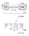
- Fig. 1 is a side view of a keyboard portion which incorporates an actuator according to the present invention;
- Fig. 2 is a plan view showing an arrangement of electromagnetic plungers;
- Fig. 3 is a sectional view showing a structure of the actuator;
- Figs. 4 and 5 are sectional views of important parts showing a modification of the actuator according to the present invention;
- Fig. 6 is a sectional view of another modification of the actuator according to the present invention;
- Fig. 7 is a plan view showing an arrangement of electromagnetic plungers of the modification of the actuator shown in Fig. 6;
- Fig. 8 is a sectional view of still another modification of the actuator according to the present invention;
- Fig. 9 is a back view showing an important part of the modification of the actuator shown in Fig. 8;
- Fig. 10 is a bottom view of the modification of the actuator shown in Fig. 8;
- Fig. 11 is a side view of the actuator according to the present invention set on a tool; and
- Fig. 12 is a sectional view of still another embodiment of the present invention.
- An embodiment of the present invention will now be described in detail with reference to the accompanying drawings.
- Figs. 1 to 3 show an embodiment of an actuator for an automatic performance piano according to the present invention. In Figs. 1 to 3, a
common yoke 4 is substantially U-shaped and extends in common with respect to a plurality ofkeys 2. Thecommon yoke 4 is disposed on the back end upper surface of a keybed 1 through abracket 23. Thecommon yoke 4 is disposed to oppose and is parallel to thelower surface 2a of thekey 2, i.e., disposed with an inclination angle which is substantially the same as that of the key 2 (about 3° with respect to a horizontal line). Inside thecommon yoke 4, a plurality ofelectromagnetic plungers 5 which correspond to therespective keys 2 are arranged in a staggered manner in two groups, i.e., the front rowelectromagnetic plunger group 5A and the back rowelectromagnetic plunger group 5B. - In this case, since the
common yoke 4 is disposed inclined so as to oppose and to be parallel to the lower surface of thekey 2 in its rest position, an interval between adrive button 12A of the front rowelectromagnetic plunger group 5A and the keylower surface 2a is set equal to that between thedrive button 12B of the back rowelectromagnetic plunger group 5B and the keylower surface 2a. In addition, since an upward stroke L₁ of thedrive button 12A close to the front end of the key, i.e., in the front row is set smaller by about 1 to 2 mm than an upward stroke L₂ of thedrive button 12B close to the back end, i.e., in the back row, uppermost positions of thebuttons keys 2 are set equal to each other. Furthermore, a shaft 14 (see Fig. 3) of eachelectromagnetic plunger 5 is disposed perpendicular to the keylower surface 2a at an initial rest position by the inclination of thecommon yoke 4, and the top end surface of thedrive button 12 opposes and is parallel to the keylower surface 2a. - Note that
reference numeral 30 denotes a balance rail; 31, a back rail; 32, a felt; 33, a balance key pin; and 34, a capstan. - According to the actuator having the above structure, since the
electromagnetic plunger 5 is disposed substantially parallel to the keylower surface 2a, the interval between thedrive button 12 of thefront row plunger 5 and the keylower surface 2a can be set equal to that between thedrive button 12 of theback row plunger 5 and the keylower surface 2a. In addition, since the upward stroke L₁ of thedrive button 12 of the front rowelectromagnetic plunger group 5A is set smaller than the upward stroke L₂ of thedrive button 12 of the back rowelectromagnetic plunger group 5B, driving force of the front rowelectromagnetic plunger group 5A is substantially equal to that of the back rowelectromagnetic plunger group 5B. Accordingly, a performance can be faithfully reproduced. Especially during reproduction of weak piano sounds, since a uniform and weak key striking force (driving force) can be obtained in both the front and back rows, a piano sound reproduction area extends to the weak piano sound side, resulting in a good reproduction property. In addition, since the top end surface of thedrive button 12 opposes and is parallel to thelower surface 2a of thekey 2 at the initial position, the entire top end surface contacts the keylower surface 2a when thedrive button 12 moves upward to drive thekey 2. Therefore, the driving force of theelectromagnetic plunger 5 acts perpendicularly on the keylower surface 2a and hence generates no component force, thereby preventing reduction in the driving force. - Fig. 4 shows a modification of the present invention, in which an
actuator 121 is disposed on the back end upper surface of akeybed 120 to correspond to the back end lower surface of akey 106. - The
actuator 121 includes anupper yoke 122 and alower yoke 123 which oppose vertically to each other, and abobbin 102 around which asolenoid coil 103 is wound is disposed between the upper andlower yokes lower yokes key 106 so as to provide a common magnetic path for a plurality ofkeys 106. The lower end of thebobbin 102 is inserted into a throughhole 125 provided to thelower yoke 123 and fitted in arecess 126 formed on theshelf 120. Aplunger 104 is fitted slidably along the axial direction, i.e., vertically inside thebobbin 102 and elastically supported by aspring 127. Abuffer member 128 such as a felt is adhered onto the upper surface of thebobbin 102, and akey drive portion 130 projects integrally at the center of the upper surface. Abutton locking portion 132 projects integrally at the center of the upper end surface of thekey drive portion 130. Thelocking portion 132 is inserted into aninsertion hole 131 provided to theupper yoke 122 and closely opposes to the back end lower surface of thekey 106. Adrive button 133 which is a characteristic feature of the present invention is detachably fitted in thebutton locking portion 132 from the above. Thebutton locking portion 132 integrally has ahead 132A and aneck 132B and has a substantially T-shaped cross-section. Thedrive button 133 is a cylinder made of an elastic material such as rubber and having an outer diameter which is substantially the same as that of thekey drive portion 130. A substantially T-shapedrecess 135 is formed at the center of the lower surface of thedrive button 133 and receives thebutton locking portion 132. A depth of therecess 135 is formed larger than a thickness of thehead 132A to form ahollow air gap 137. The upper end surface of thedrive button 133 slightly contacts the back end lower surface of the key 106. - Note that
reference numeral 139 denotes a cushion member disposed on the inner bottom surface of thebobbin 102. - In the
actuator 121 having the above structure, when a signal current is supplied to thesolenoid coil 103 to excite it, theplunger 104 is moved upward by a magnetic flux effect generated at a magnetic gap G between the upper andlower yoke 122 and theplunger 104, and its kinetic energy is transmitted to the key 106 through thedrive button 133. As a result, the key 106 is driven as if it were pushed by a human hand. - The
drive button 133 having thehollow air gap 137 is easily deformed to absorb an impact force as elastic distortion energy and as compressed energy of air inside theair gap 137. Since the drive button can be manufactured by molding and the like to obtain uniform size, shape, and elasticity, an impact characteristic at this time is very stable to contribute to stabilize an upward characteristic of the key 106. - In addition, since the outer diameter of the
drive button 133 is smaller than the inner diameter of theinsertion hole 131, thedrive button 133 can be mounted to theplunger 104 from above theupper yoke 122, and theupper yoke 122 can be easily detached without being interfered by thedrive button 133. That is, theupper yoke 122 and thedrive button 133 do not interfere with each other when these members are attached or detached, resulting in good assembly workability. Furthermore, the upper andlower yokes keys 106 to reduce the number of components. - The above actuator has a simple structure, stably prevents an impact noise upon key striking, and effectively and uniformly forms the upward characteristic of the key. Therefore the upward characteristic of the key can be improved without noise to faithfully reproduce the performance. In addition, the drive button and the upper yoke can be easily attached or detached to improve assembly workability.
- Fig. 5 shows a modification of Fig. 4 and, more particularly, a portion of the
drive button 133A. Thedrive button 133A is constituted by a cylindrical rubber member 133Aa which is fitted into the top of thekey drive portion 130 and a buffer member 133Ab such as a felt. The rubber member 133Aa has a partition 133Ae at its center, and the partition 133Ae has an opening 133Af at its center. An upward projecting edge 133Ag is provided at the periphery of the opening 133Af. Therefore, when the buffer member 133Ab is inserted from the opening 133Af of the partition 133Ae, the lower surface of the buffer member 133Ab abuts against the projecting edge 133Ag to form anair gap 137A between the lower surface and the partition 133Ae. Theair gap 137A has the same effect as that of theair gap 137 of Fig. 4. Note that the outer diameter of the buffer member 133Ab is substantially the same as that of the rubber member 133Aa. - Figs. 6 and 7 show still another embodiment of the present invention, in which an elongated hole 220 extending along the left-right direction is formed at the back end of a
shelf 201 to correspond to aback end 202a of the key 202, and akey drive unit 221 is disposed in the elongated hole 220. - The
key drive unit 221 is constituted by a pair of front and back mounting plates extending along the longitudinal direction of the elongated hole 220, a substantiallyU-shaped coupling plate 225 for connecting the lower ends of the pair of mountingplates electromagnetic plungers 205 disposed at the inner side surfaces, i.e., the opposing surfaces, of the mountingplates U-shaped yokes 206. In order to assemble thekey drive unit 221, theelectromagnetic plungers 205 are disposed at the mountingplates plates coupling plate 225. As shown in a plan view of Fig. 7, theelectromagnetic plungers 205 are disposed in a staggered manner so as to be alternately deviated from each other in the front-back direction. For example, odd-numberedelectromagnetic plungers 205A are disposed at the inner surface of the mountingplate 223 at the front side to correspond to odd-numberedkeys 202A, and even-numberedelectromagnetic plungers 205B are disposed at the inner surface of the mountingplate 224 at the back side to correspond to even-numberedkeys 202B. - In this case, mounting heights of the
electromagnetic plungers drive buttons 213A of the front rowelectromagnetic plungers 205A is set higher than that ofdrive buttons 213B of the back rowelectromagnetic plungers 205B, so that intervals between thedrive buttons 213 of all theplungers 205 and the key lower surface are equal to each other in the initial state. An upward stroke L₁ of thedrive button 213A of the front rowelectromagnetic plunger 205A is set smaller than an upward stroke L₂ of the drive button 13B of the back rowelectromagnetic plunger 205B, so that uppermost positions of the front and back drivebuttons 213 are aligned as indicated by an alternate long and short dash line in Fig. 6 and motion amounts (sinking depths of the front ends) of thekeys 202 are set equal to each other. A difference between the heights of the frontrow drive buttons 213A and the backrow drive buttons 213B is the same as a difference (L₂ - L₁) of the upward strokes. - Note that
reference numeral 230 denotes a balance rail; 231, a back rail; 232, a felt; 233, a balance key pin; and 234, a capstan. When the key 202 is depressed, it is pivoted to a substantially horizontal state. Anexcitation coil 210 and amovable iron core 211 constitute the electromagnetic plunger. - According to the actuator having the above arrangement, the key drive unit is very simple in structure, requires only a few components, and hence can be easily assembled and disassembled. In addition, the key drive unit is disposed inside the elongated hole 220 of the keybed 201 and hence almost does not project below the keybed, resulting in good outer appearance.
- Furthermore, since the interval between the front
row drive button 213A and the key lower surface is set equal to that between the backrow drive button 213B and the key lower surface, the driving force of the front rowelectromagnetic plunger 205A can be set substantially equal to that of the back rowelectromagnetic plunger 205B. Therefore, the performance can be faithfully reproduced. Especially during reproduction of a weak piano sound, since a uniform and weak key punching force (driving force) can be obtained in both the front and back rows, a piano sound reproduction area extends to the weak piano sound side, resulting in a good reproduction property. In addition, the upward strokes L₁ and L₂ are different from each other to align heights at the uppermost position of the frontrow drive button 213A and the backrow drive button 213B, so that motion amounts of all thekeys 202 can be set equal to each other. - Figs. 8 to 10 show still another modification of the actuator according to the present invention when it is applied to an automatic performance grant piano. In Figs. 8 to 10, a
key rail 320 is mounted on a keybed 301, andkeys 302 consisting of large numbers ofwhite keys 302A andblack keys 302B are disposed on thekey rail 320 to correspond tostrings 322 having respective pitches. Each key 302 is supported at its middle portion by a balancekey pin 324 extending from abalance rail 323 so as to be vertically swingable. Afront end 302a of the key 302 is normally floated by a load of anaction mechanism 330, and the back end thereof is mounted on aback rail 325 through afelt 326. Note that thekey rail 320 is formed in a lattice manner by thebalance rail 323, theback rail 325, thefront rail 327, a plurality ofkey frames 328 which integrally connects therails front rail 327, thereby preventing vibrations in thekeys 302 along the left-right direction. - The
action mechanism 330 has the same arrangement as that of a conventional action mechanism and includes asupport 334, one end of which is supported by asupport rail 332 to be vertically pivotable, and the free end of which is placed on acapstan screw 333 projecting from the back end upper surface of the key 302; a substantially L-shapedjack 335 which is pivotally disposed at the free end of thesupport 334; a verticallyswingable repetition lever 337 which is disposed above thesupport 334 through aflange 336; ahammer 342; aspring 345 which biases (counterclockwise in Fig. 8) thejack 335 and therepetition lever 337; aregulating button 346, disposed in correspondence to atender 335A of thejack 335, for regulating upward movement of the jack exceeding a predetermined amount; a back check 347, projecting from the back end upper surface of the key 302, for receiving thehammer 342 which pivots and returns after striking a string, and the like. Thehammer 342 has ahammer shank 338, ahammer wood 339, a hammer felt 340, and ahammer roller 341. One end of thehammer shank 338 is supported by ashank rail 344 through aflange 343 to be vertically pivotable. Thehammer roller 341 is normally received by therepetition lever 337. - When the key 302 is depressed and the
capstan screw 333 moves upward together with the key 302 to push thesupport 334 upward, thesupport 334 pivots counterclockwise in Fig. 8 about a connecting portion with theflange 331. Then, thejack 335 moves upward together with thesupport 334 to push thehammer roller 341 upward, the hammer pivots upward, and the hammer felt 340 strikes thestring 322. Thejack 335 is prevented from any further movement in the middle of upward movement because thetender 335A abuts against theregulating button 346. Thejack 335 is pivoted clockwise in Fig. 8 by a small amount of angular interval against thespring 345, so that the upper end of thejack 335 is temporarily removed from a position under thehammer roller 341. Thejack 335 pivots and returns when thesupport 334 pivots and moves downward after thehammer 342 strikes thestring 322, and the upper end of thejack 335 again moves toward the position under thehammer roller 341, thereby enabling the next string striking operation. After striking thestring 322, thehammer 342 pivots and returns by gravity and by impact force of thestring 322, thehammer roller 341 is received by therepetition lever 337, and thehammer wood 339 is received by the back check 347 so as not to jump up and hence returns to the initial position. - A well-known
damper mechanism 350 which cooperates with the key 302 is disposed behind the key 302. Thedamper mechanism 350 normally prevents vibration in thestring 322 and releases it during the key striking operation. Thedamper mechanism 350 includes adamper lever 352, the back end of which is supported by thesupport 351 to be vertically pivotable, and the front end of which extends above the back end of the key 302, adamper wire 354, the lower end of which is connected to thedamper lever 352 through adamper block 353, and adamper 355, mounted to the upper end of thedamper wire 354, for urging thestring 322 from the above, so that thedamper lever 352 is pushed upward by the back end of the key 302 during the key striking operation. Thedamper mechanism 350 is also operated by a pedal mechanism (not shown), and in this case, all the damper mechanisms are operated at the same time to release all thestrings 322. - An
elongated hole 360 which extends along the left-right direction is formed at the back end of theshelf 301 in correspondence to theback end 302b, and akey drive unit 361 is disposed inside theelongated hole 360 to be adjustable along the front-back direction, the left-right direction, and vertically. Thekey drive unit 361 includes a substantiallyU-shaped base bracket 362, which is obtained by bending a metal plate of, e.g., soft iron so as to be opened at its upper and both side surfaces and extends in common with respect to a plurality ofkeys 302, and a plurality ofelectromagnetic plungers 305, which are disposed inside thebase bracket 362 to face the upper opening thereof so as to correspond to therespective keys 302. Thebase bracket 362 constitutes the common yoke, and adrive button 313 of eachelectromagnetic plunger 305 closely opposes or abuts against the back end lower surface of thecorresponding key 302. In this case, theelectromagnetic plungers 305 are disposed alternately deviated from each other along the front-back direction, i.e., arranged in a staggered manner, thereby preventing interference between the adjacent plungers. In thekey drive unit 361, the lower portion of thebase bracket 362 projects below thekeybed 301 and inserted into theelongated hole 360, so that theunit 361 is supported by a pair of left and right reinforcingbrackets key drive unit 361 is positioned and fixed between the reinforcingbrackets mechanism 366 for adjusting along the front-back direction, amechanism 367 for adjusting along the left-right direction, and amechanism 368 for vertical adjustment. The reinforcingbrackets portions screws 370 and nuts (not shown). - The
mechanism 366 for adjusting thekey drive unit 361 along the front-back direction is constituted by a total of four (two pairs) adjustingscrews brackets brackets base bracket 362. Therefore, when either the front or the back adjusting screws, e.g., thefront screws 372A and 372C are sufficiently loosened beforehand and theback screws base bracket 362 is urged by thescrews key drive unit 361 is moved forward. On the contrary, when theback screws front screws 372A and 372C are gradually tightened, thekey drive unit 361 is moved backward. Thereafter, the adjustingscrews base bracket 362, so that thekey drive unit 361 is completely prevented from being moved along the front-back direction. - The
mechanism 367 for adjusting thekey drive unit 361 along the left-right direction is constituted by a pair of right and left adjustingscrews 374A and 374B which are provided at both sides of theunit 361 and are screwed into L-shapedmetal plates elongated hole 360 on the lower surface of the keybed. On the other hand, as shown in Fig. 9, side covers 378 and 379 includingguide receivers 377 are respectively mounted at both side surfaces of thebase bracket 362, and the distal ends of thescrews 374A and 374B abut against theguide receivers 377. Therefore, similar to the case described above, when either of the adjusting screws, e.g., the screw 374A is loosened beforehand and theother screw 374B is gradually tightened, theguide receiver 377 is urged and thekey drive unit 361 is moved in the left direction of Fig. 10. On the contrary, when thescrew 374B is loosened beforehand and the screw 374A is tightened gradually, thekey drive unit 361 is moved in the right direction of Fig. 10. By tightening thescrews 374A and 374B to urge theguide receivers 377, the left-right movement of thekey drive unit 361 is regulated and prevented. - The
mechanism 368 for vertically adjusting thekey drive unit 361 is constituted by a pair of right and left adjustingscrews brackets base bracket 362 throughguide spacers 382 to be described later. When thescrews key drive unit 361 is vertically adjusted. - It is a matter of course that, when the
key drive unit 361 is adjusted along the front-back direction by operating the adjustmechanism 366, thekey drive unit 361 must be released from the fixed state by the adjustmechanism 367. Similarly, when thekey drive unit 361 is adjusted along the left-right direction by operating the adjustmechanism 367, thekey drive unit 361 must be released from the fixed state by the adjustmechanism 366. In addition, when theother adjusting mechanism 368 is operated, thekey drive unit 361 must be released from the fixed state by the other two adjustmechanisms - A substantially
U-shaped guide member 390 is fixed on the inner bottom surface of each of thebrackets member 390 faces upward, and theguide spacers 382 are fixed on the lower surface of thebase bracket 362 through a guide 391 to correspond to theguide member 390. The guide 391 is formed similarly to and smaller than theguide member 390 to obtain a substantially U-shape, and fixed on the lower surface of thebase bracket 362 so that its open portion faces downward. The guide 391 is inserted into theguide member 390 from the above so as to be vertically movable between left andright side walls guide member 390. Pairs ofheight positioning bolts bolts brackets brackets base bracket 362 by thebolts - After the pair of right and left reinforcing
brackets bolts key drive unit 361 having the above structure is set on a key drive unit mounting tool (jack) 400, as shown in Fig. 11, and then inserted into theelongated hole 360 from below thekeybed 301. Thereafter, the mountingportions brackets screw 370, and thekey drive unit 361 is adjusted along the front-back direction, the left-right direction, and vertically by the three adjustingmechanisms unit 361 at the predetermined position. - Note that
reference numeral 401 in Fig. 3 denotes a wooden protection block, disposed on the lower surface of the keybed 301, at a withdrawn position on the low-pitched sound side, for protecting thekey drive unit 361 from an unexpected external force when the piano is raised while transporting. - As has been described above, according to the actuator having the above structure, a plurality of
electromagnetic plungers 305 are arranged on thebase bracket 362 beforehand at intervals each corresponding to a width of the key 302 to obtain thekey drive unit 361, and thekey drive unit 361 is inserted into theelongated hole 360 of the keybed 301 and adjusted along the front-back direction, the left-right direction, and vertically by the three adjustmechanisms key drive unit 361 is reliably fixed at the predetermined position. - In addition, when the
electromagnetic plungers 305 are once positioned and fixed to thebase bracket 362, eachelectromagnetic plunger 305 need not be individually adjusted when theunit 361 is mounted, resulting in an easy assembly. Furthermore, since the adjustmechanisms key drive unit 361 is moved along the desired direction by simply adjusting the screws, adjustment can be easily performed. Since the unit can be moved upward and downward as a whole, theaction mechanism 330 and thekeys 302 can be easily put in and taken out when the piano is tuned. - Note that, in the above embodiment, a description has been made with reference to the case in which the present invention is applied to the automatic performance grand piano. However, the present invention is not limited to the above embodiment but can be applied to an automatic performance upright piano.
- In addition, in the above embodiment, the
mechanism 366, for adjusting thekey drive unit 361 along the front-back direction, is constituted by two pairs of, i.e., a total of four adjustingscrews brackets mechanism 368, for adjusting thekey drive unit 361 vertically, is constituted by the pair of right and left adjustingscrews - Fig. 12 shows still another embodiment of the present invention. In this embodiment, a
common yoke 504 is mounted to a keybed 501 so that height and inclination of thecommon yoke 504 can be adjusted. A plurality of electromagnetic plungers 505 are disposed between anupper plate 504A and alower plate 504B of thecommon yoke 504. The electromagnetic plungers 505 have the same structure as that in Fig. 1, and are disposed to oppose to each key 502 in a direction perpendicular to the paper surface. In addition, the electromagnetic plungers 505 are divided into a front rowelectromagnetic plunger group 505A and a back rowelectromagnetic plunger group 505B in a staggered manner. In addition, as in the embodiment described above, thecommon yoke 504 incorporating the electromagnetic plungers 505 as in the above-mentioned manner is disposed inclined so as to oppose and to be parallel to the lower surface of the key 502 in its rest position, an interval between adrive button 512A of the front rowelectromagnetic plunger group 505A and a keylower surface 502a is set equal to that between a drive button 512B of the back rowelectromagnetic plunger group 505B and the keylower surface 502a. Structures of other portions are the same as shown in Figs. 1 and 3, and the same parts as shown in Figs. 1 and 3 are denoted by the same reference numerals added with 500. This embodiment is characterized by mounting a plurality ofmechanisms 550 arranged in front and back rows at proper portions of thecommon yoke 504 which do not adversely affect the arrangement of the electromagnetic plungers 505, such that themechanisms 550 support thecommon yoke 504 so as to adjust its height and inclination. Eachmechanism 550 includes ascrew 551, aspacer 552, aspring 553, and a fixingmember 554, such as a nut, which is buried in thekeybed 501. A throughhole 552a is provided to thespacer 552 so as to lock the head of thescrew 551 to pivot it. Thespacer 552 includes a spacer portion which is disposed between theupper plate 504A and thelower plate 504B of thecommon yoke 504 to define an interval therebetween, and a stopper portion with a suitable length which extends downwardly therefrom through a hole opened in thelower plate 504B. The stopper portion defines the minimum interval between thecommon yoke 504 and keybed 501 to be a distance which does not pose a structural problem. The surface of the keybed 501 opposing thecommon yoke 504 has arecess 501a. Aspring 553 is disposed between the bottom surface of therecess 501a and thelower plate 504B of thecommon yoke 504 so as to surround the stopper portion of thespacer 552 and thescrew 551. Thescrew 551 is screwed through the throughhole 552a in the fixingmember 554 such as a nut which is fixed to the keybed 501 from theupper plate 504A of thecommon yoke 504. Thescrews 551 in front and back rows are selectively screwed in or out to adjust the height and inclination of thecommon yoke 504. Therefore, the upper surfaces of thedrive buttons 512A and 512B are rendered parallel to thelower surface 502a of the key and the distances between each drive button and the key are made equal.
Claims (14)
each of said electromagnetic plunger units having an excitation coil and a plunger,
a key drive portion, provided at the distal end of said plunger, for driving the key,
said actuator characterized in that said electromagnetic plunger units are arranged along the key arrangement direction to be deviated from each other in the front-back direction of the key in a staggered manner,
and that a motion stroke of said key drive portion of said electromagnetic plunger unit in one row is made smaller than a motion stroke of said key drive portion of said electromagnetic plunger unit in the other row.
Applications Claiming Priority (10)
| Application Number | Priority Date | Filing Date | Title |
|---|---|---|---|
| JP36267/86U | 1986-03-14 | ||
| JP3626986U JPH0331996Y2 (en) | 1986-03-14 | 1986-03-14 | |
| JP55042/86 | 1986-03-14 | ||
| JP1986036266U JPH0310550Y2 (en) | 1986-03-14 | 1986-03-14 | |
| JP3626786U JPS62149093U (en) | 1986-03-14 | 1986-03-14 | |
| JP36269/86U | 1986-03-14 | ||
| JP36270/86U | 1986-03-14 | ||
| JP36266/86U | 1986-03-14 | ||
| JP1986036270U JPH0535435Y2 (en) | 1986-03-14 | 1986-03-14 | |
| JP61055042A JPS62212694A (en) | 1986-03-14 | 1986-03-14 | Actuator for automatically performing piano |
Publications (3)
| Publication Number | Publication Date |
|---|---|
| EP0237357A2 true EP0237357A2 (en) | 1987-09-16 |
| EP0237357A3 EP0237357A3 (en) | 1989-03-29 |
| EP0237357B1 EP0237357B1 (en) | 1992-11-25 |
Family
ID=27521777
Family Applications (1)
| Application Number | Title | Priority Date | Filing Date |
|---|---|---|---|
| EP87302166A Expired - Lifetime EP0237357B1 (en) | 1986-03-14 | 1987-03-13 | Actuator for automatic performance piano |
Country Status (3)
| Country | Link |
|---|---|
| US (1) | US4741237A (en) |
| EP (1) | EP0237357B1 (en) |
| DE (1) | DE3782753T2 (en) |
Cited By (1)
| Publication number | Priority date | Publication date | Assignee | Title |
|---|---|---|---|---|
| WO1992002010A1 (en) * | 1990-07-19 | 1992-02-06 | Broadmoore Laurence G | Solenoid mounting systems for player and reproducing pianos |
Families Citing this family (7)
| Publication number | Priority date | Publication date | Assignee | Title |
|---|---|---|---|---|
| JP2555777Y2 (en) * | 1993-06-03 | 1997-11-26 | ヤマハ株式会社 | Actuator for automatic performance piano |
| US5861566A (en) * | 1995-12-28 | 1999-01-19 | Yamaha Corporation | Automatic player piano having frame structure self-aligned with keyboard for exactly positioning key actuators arranged in staggered manner |
| US20060272469A1 (en) * | 1998-09-04 | 2006-12-07 | David Meisel | Key actuation systems for keyboard instruments |
| JP4548170B2 (en) * | 2005-03-23 | 2010-09-22 | ヤマハ株式会社 | Keyboard instrument |
| WO2018132965A1 (en) * | 2017-01-18 | 2018-07-26 | Sunland Information Technology Co., Ltd. | An automatic playing system |
| CN108389562A (en) * | 2018-02-11 | 2018-08-10 | 牡丹江师范学院 | A kind of multimedia piano and its automatic Playing method, system |
| JP7230441B2 (en) * | 2018-11-09 | 2023-03-01 | ヤマハ株式会社 | Vibration unit, musical instrument |
Citations (3)
| Publication number | Priority date | Publication date | Assignee | Title |
|---|---|---|---|---|
| GB1145029A (en) * | 1965-10-23 | 1969-03-12 | Dale Electronics | Improvements in or relating to keyboard operating apparatus |
| GB1186497A (en) * | 1969-02-04 | 1970-04-02 | Dale Electronics | Player Piano Key Actuating Assembly |
| US4513652A (en) * | 1981-09-08 | 1985-04-30 | Nippon Gakki Seizo Kabushiki Kaisha | Solenoid actuator for use in automatic performance piano |
Family Cites Families (3)
| Publication number | Priority date | Publication date | Assignee | Title |
|---|---|---|---|---|
| US784508A (en) * | 1904-08-19 | 1905-03-07 | Joseph Weber | Electrically-actuated piano. |
| US4031796A (en) * | 1976-04-28 | 1977-06-28 | Teledyne, Inc. | Solenoid mounting assembly for musical keyboard |
| US4451270A (en) * | 1982-06-30 | 1984-05-29 | Bend Research, Inc. | Absorption process for producing oxygen and nitrogen and solution therefor |
-
1987
- 1987-03-12 US US07/025,287 patent/US4741237A/en not_active Expired - Lifetime
- 1987-03-13 EP EP87302166A patent/EP0237357B1/en not_active Expired - Lifetime
- 1987-03-13 DE DE8787302166T patent/DE3782753T2/en not_active Expired - Fee Related
Patent Citations (3)
| Publication number | Priority date | Publication date | Assignee | Title |
|---|---|---|---|---|
| GB1145029A (en) * | 1965-10-23 | 1969-03-12 | Dale Electronics | Improvements in or relating to keyboard operating apparatus |
| GB1186497A (en) * | 1969-02-04 | 1970-04-02 | Dale Electronics | Player Piano Key Actuating Assembly |
| US4513652A (en) * | 1981-09-08 | 1985-04-30 | Nippon Gakki Seizo Kabushiki Kaisha | Solenoid actuator for use in automatic performance piano |
Cited By (1)
| Publication number | Priority date | Publication date | Assignee | Title |
|---|---|---|---|---|
| WO1992002010A1 (en) * | 1990-07-19 | 1992-02-06 | Broadmoore Laurence G | Solenoid mounting systems for player and reproducing pianos |
Also Published As
| Publication number | Publication date |
|---|---|
| US4741237A (en) | 1988-05-03 |
| EP0237357A3 (en) | 1989-03-29 |
| DE3782753T2 (en) | 1993-06-09 |
| DE3782753D1 (en) | 1993-01-07 |
| EP0237357B1 (en) | 1992-11-25 |
Similar Documents
| Publication | Publication Date | Title |
|---|---|---|
| US7858858B2 (en) | Upright piano | |
| US5861566A (en) | Automatic player piano having frame structure self-aligned with keyboard for exactly positioning key actuators arranged in staggered manner | |
| US20020059862A1 (en) | Keyboard musical instrument for exactly producing tones and hammer sensor varying output signal exactly representing physical quantity of hammer | |
| EP0237357B1 (en) | Actuator for automatic performance piano | |
| US5600077A (en) | Damper mechanism provided in a grand piano | |
| KR100273868B1 (en) | Keyboard instrument with hammer stopper realized by parallel quadrilateral link mechanism | |
| KR0132545B1 (en) | Keyboard instrument selectively entering into acoustic sound mode and silent mode through angular motion of key bed structure | |
| US8013228B2 (en) | Electronic keyboard musical instrument having key actuators | |
| US7816598B2 (en) | Electronic keyboard musical instrument having key actuators | |
| US7238868B2 (en) | Keyboard musical instrument equipped with automatic player and method for retrofitting keyboard musical instrument | |
| EP0655727B1 (en) | Keyboard musical instrument with movable key bed for performing music without acoustic sounds | |
| US6448481B2 (en) | Pedal mechanisms assembled into unit and keyboard musical instrument equipped with the same | |
| US6552251B2 (en) | Actuating device easily assembled and keyboard musical instrument equipped therewith | |
| US6194649B1 (en) | Keyboard musical instrument equipped with partially repaireable change-over mechanism for changing hammer stopper | |
| US5506369A (en) | Electromagnetic actuator used for keyboard musical instrument | |
| EP0291914A2 (en) | Automatic player piano | |
| US6265647B1 (en) | Keyboard musical instrument having hammer stopper changed between free position and blocking position through turn on horizontal plane | |
| JP4206597B2 (en) | Optical sensor | |
| JPH10161649A (en) | Automatic playing device of keyed instrument | |
| JP3714349B2 (en) | Silencer for keyboard instrument and keyboard instrument | |
| US5527987A (en) | Keyboard musical instrument with solenoid-operated actuators arranged in interdigitated manner | |
| US11250820B2 (en) | Stopper rail for silent piano | |
| JPH10161650A (en) | Automatic playing device of keyed instrument and its manufacture | |
| JPH04299393A (en) | Support mechanism for sound generation body | |
| JP2595620B2 (en) | Key drive for keyboard instruments |
Legal Events
| Date | Code | Title | Description |
|---|---|---|---|
| PUAI | Public reference made under article 153(3) epc to a published international application that has entered the european phase |
Free format text: ORIGINAL CODE: 0009012 |
|
| AK | Designated contracting states |
Kind code of ref document: A2 Designated state(s): DE GB |
|
| 17P | Request for examination filed |
Effective date: 19880222 |
|
| RAP1 | Party data changed (applicant data changed or rights of an application transferred) |
Owner name: YAMAHA CORPORATION |
|
| PUAL | Search report despatched |
Free format text: ORIGINAL CODE: 0009013 |
|
| AK | Designated contracting states |
Kind code of ref document: A3 Designated state(s): DE GB |
|
| 17Q | First examination report despatched |
Effective date: 19910225 |
|
| GRAA | (expected) grant |
Free format text: ORIGINAL CODE: 0009210 |
|
| AK | Designated contracting states |
Kind code of ref document: B1 Designated state(s): DE GB |
|
| REF | Corresponds to: |
Ref document number: 3782753 Country of ref document: DE Date of ref document: 19930107 |
|
| PLBE | No opposition filed within time limit |
Free format text: ORIGINAL CODE: 0009261 |
|
| STAA | Information on the status of an ep patent application or granted ep patent |
Free format text: STATUS: NO OPPOSITION FILED WITHIN TIME LIMIT |
|
| 26N | No opposition filed | ||
| PGFP | Annual fee paid to national office [announced via postgrant information from national office to epo] |
Ref country code: GB Payment date: 19970304 Year of fee payment: 11 |
|
| PGFP | Annual fee paid to national office [announced via postgrant information from national office to epo] |
Ref country code: DE Payment date: 19970321 Year of fee payment: 11 |
|
| PG25 | Lapsed in a contracting state [announced via postgrant information from national office to epo] |
Ref country code: GB Free format text: LAPSE BECAUSE OF NON-PAYMENT OF DUE FEES Effective date: 19980313 |
|
| GBPC | Gb: european patent ceased through non-payment of renewal fee |
Effective date: 19980313 |
|
| PG25 | Lapsed in a contracting state [announced via postgrant information from national office to epo] |
Ref country code: DE Free format text: LAPSE BECAUSE OF NON-PAYMENT OF DUE FEES Effective date: 19981201 |