EP0237015A2 - Regeleinrichtung für Luftverteiler mit veränderlichem Luftvolumen - Google Patents
Regeleinrichtung für Luftverteiler mit veränderlichem Luftvolumen Download PDFInfo
- Publication number
- EP0237015A2 EP0237015A2 EP87103396A EP87103396A EP0237015A2 EP 0237015 A2 EP0237015 A2 EP 0237015A2 EP 87103396 A EP87103396 A EP 87103396A EP 87103396 A EP87103396 A EP 87103396A EP 0237015 A2 EP0237015 A2 EP 0237015A2
- Authority
- EP
- European Patent Office
- Prior art keywords
- thermostat
- slot
- air
- sleeve
- improvement
- Prior art date
- Legal status (The legal status is an assumption and is not a legal conclusion. Google has not performed a legal analysis and makes no representation as to the accuracy of the status listed.)
- Granted
Links
- 238000009434 installation Methods 0.000 title abstract description 21
- 230000006872 improvement Effects 0.000 claims description 37
- 230000001143 conditioned effect Effects 0.000 claims description 27
- 238000007599 discharging Methods 0.000 claims description 9
- 230000033001 locomotion Effects 0.000 claims description 9
- 239000006260 foam Substances 0.000 claims description 7
- 230000000694 effects Effects 0.000 claims description 6
- 238000012544 monitoring process Methods 0.000 claims description 2
- 230000007246 mechanism Effects 0.000 abstract description 19
- 230000004048 modification Effects 0.000 abstract 1
- 238000012986 modification Methods 0.000 abstract 1
- 238000005259 measurement Methods 0.000 description 8
- 230000009471 action Effects 0.000 description 4
- 238000005192 partition Methods 0.000 description 4
- 239000002184 metal Substances 0.000 description 3
- 238000010276 construction Methods 0.000 description 2
- 230000000593 degrading effect Effects 0.000 description 2
- 229920001821 foam rubber Polymers 0.000 description 2
- 238000007689 inspection Methods 0.000 description 2
- 230000013011 mating Effects 0.000 description 2
- 230000002411 adverse Effects 0.000 description 1
- 238000004378 air conditioning Methods 0.000 description 1
- 238000013459 approach Methods 0.000 description 1
- 230000009286 beneficial effect Effects 0.000 description 1
- 230000000740 bleeding effect Effects 0.000 description 1
- 230000008859 change Effects 0.000 description 1
- 230000006835 compression Effects 0.000 description 1
- 238000007906 compression Methods 0.000 description 1
- 230000002950 deficient Effects 0.000 description 1
- 238000013461 design Methods 0.000 description 1
- 238000003780 insertion Methods 0.000 description 1
- 230000037431 insertion Effects 0.000 description 1
- 239000000463 material Substances 0.000 description 1
- 238000000034 method Methods 0.000 description 1
- 238000003825 pressing Methods 0.000 description 1
Images

Classifications
-
- G—PHYSICS
- G05—CONTROLLING; REGULATING
- G05D—SYSTEMS FOR CONTROLLING OR REGULATING NON-ELECTRIC VARIABLES
- G05D23/00—Control of temperature
- G05D23/185—Control of temperature with auxiliary non-electric power
-
- F—MECHANICAL ENGINEERING; LIGHTING; HEATING; WEAPONS; BLASTING
- F24—HEATING; RANGES; VENTILATING
- F24F—AIR-CONDITIONING; AIR-HUMIDIFICATION; VENTILATION; USE OF AIR CURRENTS FOR SCREENING
- F24F11/00—Control or safety arrangements
- F24F11/70—Control systems characterised by their outputs; Constructional details thereof
- F24F11/72—Control systems characterised by their outputs; Constructional details thereof for controlling the supply of treated air, e.g. its pressure
- F24F11/74—Control systems characterised by their outputs; Constructional details thereof for controlling the supply of treated air, e.g. its pressure for controlling air flow rate or air velocity
- F24F11/76—Control systems characterised by their outputs; Constructional details thereof for controlling the supply of treated air, e.g. its pressure for controlling air flow rate or air velocity by means responsive to temperature, e.g. bimetal springs
Definitions
- This invention relates generally to the controls for an air conditioning system and more particularly to an improved installation which facilitates servicing and adjustment of the control components for a variable volume air diffuser.
- U.S. Patent Nos. 4,399,739 to Dean; 4,356,963 to Edwards et al., 4,331,291 to Dean and 4,312, 475 to Edwards et al. relate to variable volume air distribution systems in which operating power for the flow control mechanism is obtained from the high pressure air supply in the ventilating ducts of a building.
- a variable volume control device and an air diffuser can be combined in a single integrated assembly to provide an economical unit for controlling the distribution of conditioned air to a relatively large number of temperature control zones.
- Devices in which the duct pressure is used to supply operating power for the controls are commonly referred to in the industry as self-powered controlled diffusers.
- the diffuser mounted thermostat it is also beneficial in a number of respects for the diffuser mounted thermostat to be capable of being installed and removed from below the ceiling. This makes it easier to assure a wide open thermostat condition during adjustment of the high limit of the control. It is also makes inspection and replacement of the thermostat easier in the event that problems arise with a defective thermostat.
- An ability to measure flow during adjustment is also important.
- slave units can be converted to stand alone units easily at a later time when the building has been completed and is occupied.
- the present invention is directed to an improved installation of the controls for a variable air volume diffuser, and among its objects are to provide an installation in which actual measurement of the air flow is facilitated, adjustment of the maximum flow rate is easily made from below the ceiling, and the thermostat can . be installed and removed from below the ceiling.
- control components are housed in a control compartment which is separated from the plenum and air diffuser by a transverse bulk head.
- the pneumatic line of the control circuit to which the flow velocity signal is applied is connected with one leg of a Tee fitting having a second leg feeding through the bulkhead and connected with a perforated or slotted tube that extends within the air diffuser to sense the air flow rate.
- the third leg of the Tee points downwardly and is located next to the bulkhead where a tube inserted from below the ceiling can be slipped over it after being guided along the bulkhead. Because the flow measurement is made on the low pressure side of the system, the third leg of the Tee can be vented so long as its port is maintained small enough to avoid substantially degrading the performance of the device.
- the Tee fitting is recessed up in the control compartment where it is out of sight and yet can be accessed easily for measurement of the flow rate by technicians and service men.
- an improved mechanism for adjustment of the control to vary the maximum air discharge rate.
- the mechanism includes a long screw which is threaded through an elongated sleeve.
- a cylindrical tip on the end of the screw fits closely in a mating pocket formed in a.bracket that extends from the exhaust tube which is axially adjustable in order to adjust the maximum flow rate.
- a spring acts on the bracket to hold it against the screw so that threaded advancement and retraction of the screw effects axial adjustment of the exhaust tube.
- the close fit of the.tip of the adjustment screw in the pocket, along with the long surfaces of contact between the sleeve and screw prevent the mechanism from wobbling significantly, and the stability of the adjustment mechanism is enhanced accordingly.
- the screw extends down to the slot in the control compartment where it is easily accessible from below the ceiling when adjustment is required.
- Another important feature of the invention is the arrangement of the installation to permit insertion and removal of the thermostat from below the ceiling.
- a spring clip is provided in the control compartment to hold the thermostat at the proper position, and a foam insulating block is strategically located to seal the thermostat housing against infiltrating cold air from cracks in the ductwork or other components of the air distribution system.
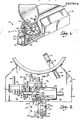
- the present invention is directed to a control installation which is generally designated by numeral 10 in Figs. 1 and 2 and which serves to control the distribution of conditioned air in a building.
- the conditioned air is passed by a fan (not shown) through ductwork which includes a duct 12 having an underlying plenum 14.
- An air diffuser 16 (Fig. 3) receives conditioned air from the plenum 14 and discharges it through the usual diffuser slot 18 into the conditioned space served by the control installation 10.
- Diffuser 16 and the other components of the air distribution system are ceiling mounted, and the discharge slot 18 is normally flush with the ceiling of the conditioned pace served by the diffuser.
- a pneumatic control circuit acts to inflate and deflate an actuator bag 20 (Fig. 3) which serves as a flow control device to control the flow of conditioned air from the duct 12 into the plenum 14 and through the diffuser slot 18.
- the operating components of the pneumatic circuit in the control installation 10 are housed in a control compartment 22 which is separated from the plenum 14 by a transverse bulk head 24 secured to extend across the end of the plenum.
- the control compartment 22 includes on its lower portion a thermostat compartment 25 (Fig. 2) which houses an aspirating type thermostat 26.
- the thermostat compartment 25 is formed as an extension of the diffuser 16 and is separated from the diffuser by a bulkhead or partition 28 which forms a downward extension of bulkhead 24.
- the thermostat compartment 25 has opposite sides 30 which are extensions of the sides of the air diffuser, and it also includes a slot 32 which is formed as an extension of the diffuser slot 18.
- An end plate 34 defines the end of the thermostat compartment opposite partition 28.
- a pressure regulator 36 and a pneumatic amplifying control relay 38 Extending downwardly from the body of the relay 38 are a pair of vertical posts 40 secured at their lower ends to an L shaped mounting bracket 42 which is connected with the bulkhead 24.
- the body of the pressure regulator 36 is provided with a pair downwardly projecting feet 44 (Fig. 2) which are secured at their lower ends to a horizontal plate 46 which forms an extension on one side of the mounting bracket 42.
- the amplifying control relay 38 is of the same general type as that shown in U.S. patent number 4,331,291 which is incorporated herein by reference. As explained in the referenced patent, relay 38 has an internal diaphragm 48 (Fig. 5) which controls the bleeding of air through an exhaust port 50 formed on the upper end of an exhaust tube 52.
- the exhaust tube 52 connects telescopically with a hose 54 which extends to a manifold 56.
- Another hose 58 extends from manifold 56 and connects with a fitting 60 which extends through the bulkhead 24 as best shown in Fig. 3.
- the actuator bag 20 is connected with the fitting 60 by line 64, and the condition of the actuator bag controls the rate at which air is able to pass from the duct 12 into the plenum 14.
- Relay 38 has an exhaust port 65 (Fig. 2). Also extending from the relay 38 is a velocity sensing line 66 which applies to the relay a signal indicative of the discharge velocity of the conditioned air. As best shown in Fig. 3, line 66 connects with the top leg of a Tee fitting 68 having its horizontal leg extending through and connected with the bulkhead 24. Within the plenum 14, the horizontal leg of fitting 70 connects with a sensor tube 71 having a plurality of spaced apart perforations or slots 71a located to sense the velocity of the air that is discharging into the conditioned space from the air diffuser 16.
- the third leg of the Tee fitting 70 extends downwardly along the surface of bulkhead 24 and terminates at its lower end in a small port 72 (Fig. 4).
- Port 72 is recessed well up in the control compartment 22 and is located adjacent to the bulkhead 24 at location well above slot 32.
- port 72 serves the purpose of allowing an actual measurement to be taken of the velocity of the discharging air.
- a tube 74 (Fig. 3) carrying a gauge 76 on its end can be extended upwardly through slot 32 from below the ceiling.
- Tube 74 can be guided along the partition 28 of the bulkhead such that its end can easily be fitted on the lower end of the T ee fitting 70 and over the port 72.
- the pneumatic velocity signal which is present at port 72 is then transmitted through tube 74 to the gauge 76. Little difficulty is involved in properly applying the tube 74 to the Tee fitting 70 because the tube can be guided along the surface of partition 28.
- Port 72 is preferably uncapped so that it continuously bleeds to the atmosphere. This can be done without appreciably degrading the performance of the control so long as the effective cross sectional area of the port 72 is no greater than about 10% of the total effective area presented by the slots 71a in the velocity sensing tube. When port 72 is this small, the amount of air that bleeds through it is too small to have a significant adverse affect on the performance of the unit. Consequently, the size of port 72 is maintained at less than 10% the combined size of perforations or slots 71a.
- the pressure regulator 36 is identical to that shown in patent application Serial No. 775,533, filed September 13, 1985 by Raymond H. Dean, which application is incorporated by reference herein.
- the pressure regulator 36 is connected with relay 38 in the manner shown in Fig. 2 of the referenced application.
- the regulator 36 has a loop 78 which connects the control and output chambers located on opposite sides of its diaphragm (not shown).
- the regulator 36 has an output line 80 which extends from its underside for output chamber to connection with the top side of relay 38.
- a supply line 82 which supplies operating power to the regulator 36 extends from manifold 56 to the underside (output chamber) of the regulator.
- Regulator 36 also has a thermostat line 83 which extends from the top side of the regulator to connection with a tube 84 extending from the thermostat 26a, as shown in Fig. 3.
- the thermostat tube 84 terminates in a port 86 which is controlled by a metal strip 88 included in the thermostat.
- the pressure of the primary air supply in duct 12 is picked up by a fitting 90 which is mounted in the duct and has an opening 92 for receiving the duct pressure.
- the duct pressure is transmitted from fitting 90 along hose 94 to a filter 96, and from the filter to the manifold 56.
- the supply pressure is transmitted from manifold 56 to lines 54, 58 and 82.
- the thermostat 26 is an aspirating type thermostat having a thin generally rectangular housing 98.
- a pair of feet 100 project from the bottom of housing 98. Between the feet 100, the bottom of the thermostat housing 98 is open to provide a slot 102 into which air is drawn from the conditioned space located below slot 32.
- Mounted in the thermostat housing 98 adjacent to slot 102 is a temperature sensitive bimetal strip 104 which acts on strip 88 in a manner to move strip 88 toward and away from port 86.
- the bimetal strip 104 can be adjusted by a lever 106 in order to thereby adjust the setting of the thermostat. It is noteworthy that lever 106 is located adjacent to slot 32 and is readily accessible from below the ceiling.
- Thermostat 26 is an aspirating type thermostat to which aspirating air is supplied through a hose 108 which extends from the supply pressure pick-up fitting 90 and connects with a tube 110 that leads into the thermostat housing 98.
- Tube 110 extends into a horizontal aspirating passage 112 which is formed through the top portion of the thermostat housing and which communicates with the open slot 102 on the bottom end of the thermostat.
- the aspirating passage 112 has its outlet end aligned with a cut-out 114 formed in end plate 34 in order to accommodate the aspirating air supplied from the duct 12.
- the aspirating air which flows through passage 112 acts by aspiration to draw air from the conditioned space into slot 32 and through the slot 102 on the bottom end of the thermostat housing. This aspirating action insures that the temperature sensitive bimetal strip 104 in the thermostat is exposed to air which is representative of the temperature in the conditioned space.
- a compliant foam rubber thermal insulating block 115 is closely fitted in the bottom portion of the thermostat compartment 25.
- the insulating block 115 extends between the opposite sides 30 of the thermostat compartment and is glued or otherwise secured in place to the sides 30 and to the bottom flanges located on opposite sides of slot 32.
- a slot 116 is formed through block 115 and has a size to closely receive the lower portion of the thermostat housing 98.
- the insulating block 115 serves to seal the bottom portion of the thermostat (where the temperature sensitive bimetal strip 104 is located) against infiltrating cold air leaking through cracks in the ductwork or other components of this system.
- the close fit of the thermostat housing in slot 116 also prevents significant side to side wobble of the thermostat housing.
- the slot 116 also maintains the thermostat firmly against the end plate 34 of the thermostat compartment where the thermostat is located as far as possible from the active portion of the air diffuser 16 through which relatively cool conditioned air passes.
- the thermostat 26 is held in place in the thermostat compartment 25 by a metal spring clip which is generally designated by numeral 118 and which is best shown in Fig. 2.
- the spring clip 118 includes opposite legs 120 which diverge as they extend downwardly from a relatively narrow throat 122 formed on the spring clip between the upper portions of the opposite legs 120.
- the legs 120 have out turned flanges 124 on their lower ends which engage the opposite sides 30 of the thermostat compartment and are preferably received in pockets 126 formed in the sides 30.
- the spring construction of the spring clip causes the legs 120 to be urged outwardly by spring action in order to maintain them against the opposite sides 30, thereby holding the spring clip in place.
- the throat 122 is aligned above slot 116 in the insulating block 115, and the throat has a size to closely accommodate the upper portion of the thermostat housing 98.
- the thermostat housing is pressed into the throat 122, the legs 120 on opposite sides of the throat grip firmly against the opposite sides of the thermostat housing to hold the thermostat in place.
- Initial installation of the thermostat 26 is achieved by first connecting the thermostat tubes 84 and 110 to the respective hoses 84 and 108.
- the thermostat housing can then be inserted upwardly through slot 116 with one end 98a facing diagonally upwardly.
- the compliance of the foam rubber allows it to be compressed as the thermostat is pushed up into the slot.
- the corner of the thermostat housing engages the end plate 34 as it is rotated, and the end 98b of the thermostat housing then remains in contact with plate 34 as the thermostat "clicks" into a square upright position.
- the thermostat can be pushed fully upwardly by pressing on the feet 100 until the thermostat is fully inserted into the throat 122 of the spring clip 118 and against the curved bight 118a on top of clip 118.
- the spring clip thereafter holds the thermostat securely in place.
- the thermostat can be initially installed in this manner from below the ceiling. It is also noteworthy that the motions and actions required to insert the thermostat are easy and natural and do not require complicated procedures.
- the spring clip 118 limits the upward movement of the thermostat and holds the top of the thermostat housing against side to side wobble.
- the legs 120 grip firmly against opposite sides of the thermostat to hold it in place and prevent it from falling downwardly out of the slot 32. It is noteworthy that the thermostat is gripped near its top end at a location remote from the temperature sensitive element 104 and adjacent to the aspirating air passage 112. Consequently, any cold that is conducted through the thermostat body by the metal spring clip 118 is carried away by the aspirating air flowing through the passage 112 before it is able to affect the sensing element 104.
- the thermostat can be removed for inspection, servicing or replacement simply by pulling downwardly to remove it from the spring clip 118 and then withdrawing it through slot 32 by reversing the steps used to install it. This can be accomplished from below the ceiling, and the thermostat can be reinserted in the manner indicated previously after it has been repaired or replaced.
- the adjustment mechanism includes an elongated vertical sleeve 128 which is secured to and extends downwardly from the mounting bracket 42.
- a passage 130 is formed through sleeve 128 and is internally threaded at 130 on its upper portion.
- the internal threads 130 extend for at least 1 / 4 inch longitudinally of sleeve 128.
- An elongated screw shank 132 extends closely through sleeve 128 and has threads 134 on its upper end portion, and the threads 134 engage the threads 130 of sleeve 128. Consequently, the turning of screw 132 in opposite directions advances and retracts the screw by threaded action.
- the top end of screw 132 is provided with a cylindrical tip 140 which fits closely in a cylindrical pocket 142 formed in the lower surface of a bracket 144.
- Bracket 144 is secured to and extends sidewardly from the exhaust tube 52.
- a fork 146 is formed on the free end of bracket 144 and closely embraces one of the posts 40 which extend from the body of relay 38.
- the post 40 serves as a guide post which cooperates with the fork 146 to guide bracket 144 up and down and to prevent the bracket from wobbling or becoming cocked or otherwise disoriented. Engagement of peg 150 against the body of relay 38 limits upward movement of screw 136.
- a compression spring 148 is coiled around a peg 150 which projects upwardly from bracket 144 at a location aligned with the axis of screw 132.
- Spring 148 acts against the bottom of the body of relay 38 at its top end and against bracket 144 at its bottom end, and the spring thereby continuously urges bracket 144 downwardly, with the force of the spring acting directly in line with screw 132 to assure that the tip 140 is maintained in pocket 142 at all times.
- the height of the peg 150 is made so that when the screw 132 is screwed up tight, the exhaust port 52 is closed but cannot be closed so hard as to damage the diaphragm 48.
- screw-132 extends downwardly and has its lower end located adjacent to the slot 32.
- the lower end of the screw is provided with a slot or hexagonal socket 138 for receiving a screwdriver or wrench 152.
- a large cut-out 154 is formed in the foam block 114 to receive the lower end portion of screw 132.
- Another large cut-out 156 is formed in block 114 at a location directly below the port 72 in order to accommodate tube 74. During normal operation, these permit pressure equalization between the vent 65 in the relay and the space being controlled.
- the wrench 152 can be applied to screw 132 from a location below the ceiling, and the wrench can be turned to turn screw 132 in order to adjust the maximum flow rate of the control.
- the screw When the screw is turned in a direction to advance upwardly through sleeve 128, it forces bracket 144 upwardly, and this in turn moves the exhaust tube 52 upwardly such that its port 50 is moved closer to the diaphragm 48.
- the screw 132 can be retracted to lower the exhaust tube 52 and thereby move port 50 away from diaphragm 48.
- the present invention provides a control installation 10 which permits actual measurement to be made of the velocity of the discharging air due to the provisions of the Tee fitting 70 and the location of its port 72 such that it can be readily accessed from below the ceiling by the tube 74.
- the thermostat 26 can be installed and serviced from below the ceiling.
- the adjustment mechanism for the maximum flow rate is constructed in a manner to avoid wobbling or other disorientation of the exhaust tube, and it is readily accessible from below the ceiling. All of these features are achieved in an economical manner and with a compact unit that is housed above the ceiling so as not to detract from the appearance of the air delivery system.
- control components control the discharge of conditioned air into the space that is served in the manner described in the referenced Patent No. 4,331,291 and the referenced application no. 775,533, to which reference may be made for a description of the operation of the control system.
- thermostat 26 In the event that it is desired to connect a particular control unit as a "slave" unit, the thermostat 26 is not used on that unit and the thermostat tubes 84 and 108 which extend from the control are pulled through the slot 116 in the foam block 114 and then are extended back up and through the cut-out 114 form through end plate 134.
- the invention further comprises the following elements in the specified or any other combination:
- said sensor conduit has a plurality of spaced apart openings therein each having a predetermined size; and said port in the lower end of said third leg of the Tee fitting has a size no greater than approximately 10% of the combined sizes of the openings in said sensor conduit.
- the improvement including: an exhaust tube in the control circuit slidable axially to adjust the maximum air flow rate through the diffuser slot; means for mounting said exhaust tube in said control compartment for generally up and down axial sliding movement; an internally threaded elongate sleeve secured in said control compartment at a fixed location offset from and generally parallel to the exhaust tube; a rigid bracket extending from said exhaust tube and having a seat surface aligned with said sleeve at a location above the sleeve; and an elongate screw threaded through said sleeve and having a top end presenting a tip engaging said seat surface, said screw having a bottom end accessible through said slot of the control compartment to effect turning of the screw for axial adjustment of the exhaust tube.
- the improvement including means for urging said bracket toward said sleeve to maintain said pocket and tip in engagement.
- the improvement including: a generally vertical guide post offset from and substantially parallel to said exhaust tube and sleeve; and a guide surface on said bracket engaging said guide post in a manner to resist wobbling of the bracket as same is moved up and down.
- said seat surface of the bracket presents a generally cylindrical pocket facing toward said sleeve; and said tip of the screw is a generally cylindrical tip fitting closely in said pocket to resist wobbling of the exhaust tube.
- the improvement including means for urging said bracket toward said sleeve to maintain said tip in said pocket.
- said urging means comprises a spring element acting against said bracket in a manner to urge same downwardly and at a location aligned with said sleeve.
- the improvement including: a generally vertical guide post offset from and substantially parallel to said exhaust tube and sleeve; and a guide surface on said bracket engaging said guide post in a manner to resist wobbling of the bracket as same is moved up and down.
- the improvement including: a thermostat having a thermostat housing and a temperature sensitive sensor element in said thermostat housing, said sensor element being included in said control circuit; means for mounting said thermostat in said control compartment at a preselected position therein with said sensor element adjacent the slot of the control compartment and exposed to the conditioned space; and a foam insulating block in said control compartment adjacent said slot thereof, said block having an opening sized to accept passage of said thermostat housing into and out of said control compartment through the slot thereof and said thermostat housing fitting closely in said opening of the block when in said preselected position.
- the improvement including: a first cut out in said insulating block substantially aligned below said third leg of the T ee fitting to provide access through the insulating block to said third leg for application of a tube thereto; and a second cut out in said insulating block substantially aligned with said screw to provide access through the insulating block to said bottom end of the screw.
- the improvement including: a thermostat having a thermostat housing and a temperature sensitive sensor element in said thermostat housing, said sensor element being included in said control circuit; means for mounting said thermostat in said control compartment at a preselected position therein with said sensor element adjacent the slot of the control compartment and exposed to the conditioned space; and a foam insulating block in said control compartment adjacent said slot thereof, said block having an opening sized to accept passage of said thermostat housing into and out of said control compartment through the slot thereof and said thermostat housing fitting closely in said opening of the block when in said preselected position.
- said - mounting means comprises a spring clip mounted in said control compartment and presenting a pair of legs for receiving the thermostat housing therebetween and gripping the thermostat housing to retain same at said preselected position.
- a control compartment housing said control circuit and having a lower end; means for mounting said exhaust tube in the control compartment for generally up and down axial sliding movement to adjust the maximum air flow rate through the outlet; an elongate internally threaded sleeve secured in said control compartment at a fixed location offset from and generally parallel to the exhaust tube; a bracket extending from said exhaust tube and having a seat surface aligned with said sleeve at a location above the sleeve; and an elongate screw threaded through said sleeve and having a top end presenting a tip engaging said seat surface , said screw having a bottom end accessible through the lower end of said
- the improvement including means for- urging said bracket toward said sleeve to maintain said pocket and tip in engagement.
- said seat surface of the bracket presents a generally cylindrical pocket facing toward said sleeve; and said tip of the screw is a generally cylindrical tip fitting closely in said pocket to resist wobbling of the exhaust tube.
- the improvement including means for urging said bracket toward said sleeve to maintain said tip in said pocket.
- said urging means comprises a spring element acting against said bracket in a manner to urge same downwardly and at a location aligned with said sleeve.
- the improvement including: a generally vertical guide post offset from and substantially parallel to said exhaust tube and sleeve; and a guide surface on said bracket engaging said guide post in a manner to resist wobbling of the bracket as same is moved up and down.
- said internally threaded sleeve has internal threads extending at least one fourth inch in the direction of the sleeve axis.
- the improvement including mating stop surfaces on said sleeve and screw for limiting the threaded extension of said screw through the sleeve.
- An improved adjustment mechanism for a tube supported for axial sliding movement to adjust a pneumatic control circuit in an air distribution control system comprising: an elongate sleeve presenting an internally threaded axial passage; means for mounting said sleeve in a fixed position with said passage offset from and substantially parallel to the tube; a rigid bracket secured to and extending from the tube, said bracket presenting a generally cylindrical pocket therein aligned with and facing toward said passage of the sleeve; an elongate threaded screw extending through said sleeve and having a threaded connection with said passage to effect advancement and retraction of the screw upon turning thereof, said screw having a generally cylindrical tip closely received in said pocket; and means for urging said bracket toward said sleeve to thereby effect axial movement of said tube when said screw is turned in opposite directions.
- said urging means comprises a spring element applying a force to said bracket at a location substantially aligned with said threaded passage.
- the adjustment mechanism including: a guide post offset from and substantially parallel to said tube and sleeve; and a guide surface on said bracket guided along said guide post in a manner to resist wobbling of the bracket as same is moved toward and away from the sleeve.
- said urging means comprises a spring element applying a force to said bracket at a location substantially aligned with said threaded passage.
- the adjustment mechanism including making stop surfaces on the axis of said screw for limiting the advancement of the.screw through the sleeve.
- a control system for an air diffuser having a plenum for directing conditioned air to the diffuser and a diffuser slot for discharging the air to a conditioned space
- the improvement comprising: a generally transverse bulkhead on said plenum and diffuser defining a control compartment and an underlying thermostat compartment arranged as extensions of the plenum and diffuser, respectively,--said thermostat compartment having opposite sides and a slot arranged as an extension of the diffuser slot; a thermostat having a housing containing a temperature sensitive sensing element included in the control system, said thermostat housing having a tube connection arranged to be coupled to a tube of the control system and said housing having an open bottom for accommodating flow of air from the conditioned space to the sensing elements; a spring clip in the thermostat compartment for holding said thermostat, said clip having opposite legs engaging said opposite sides of the thermostat compartment to hold the clip in a fixed position wherein said legs are located to receive the thermostat housing with said legs gripping the housing therebetween to releaseably hold same in place with said open bottom located in said slot of the
- said legs of the spring clip cooperate to form a throat having an inverted U shape presenting a curved bight which limits upward movement of the thermostat housing to a preselected position wherein said open bottom is exposed through said slot of the thermostat compartment and said sensing element is located in said opening of the block.
Landscapes
- Engineering & Computer Science (AREA)
- Physics & Mathematics (AREA)
- General Physics & Mathematics (AREA)
- Automation & Control Theory (AREA)
- Combustion & Propulsion (AREA)
- Mechanical Engineering (AREA)
- General Engineering & Computer Science (AREA)
- Power Engineering (AREA)
- Fluid Mechanics (AREA)
- Chemical & Material Sciences (AREA)
- Duct Arrangements (AREA)
- Compressor (AREA)
- Control Of Positive-Displacement Air Blowers (AREA)
- Reciprocating Pumps (AREA)
- Structures Of Non-Positive Displacement Pumps (AREA)
- Flow Control (AREA)
Priority Applications (1)
| Application Number | Priority Date | Filing Date | Title |
|---|---|---|---|
| AT87103396T ATE59097T1 (de) | 1986-03-10 | 1987-03-10 | Regeleinrichtung fuer luftverteiler mit veraenderlichem luftvolumen. |
Applications Claiming Priority (2)
| Application Number | Priority Date | Filing Date | Title |
|---|---|---|---|
| US06/837,888 US4648552A (en) | 1986-03-10 | 1986-03-10 | Control installation for variable volume air diffusers |
| US837888 | 1986-03-10 |
Publications (3)
| Publication Number | Publication Date |
|---|---|
| EP0237015A2 true EP0237015A2 (de) | 1987-09-16 |
| EP0237015A3 EP0237015A3 (en) | 1988-08-10 |
| EP0237015B1 EP0237015B1 (de) | 1990-12-12 |
Family
ID=25275716
Family Applications (1)
| Application Number | Title | Priority Date | Filing Date |
|---|---|---|---|
| EP87103396A Expired - Lifetime EP0237015B1 (de) | 1986-03-10 | 1987-03-10 | Regeleinrichtung für Luftverteiler mit veränderlichem Luftvolumen |
Country Status (5)
| Country | Link |
|---|---|
| US (1) | US4648552A (de) |
| EP (1) | EP0237015B1 (de) |
| AT (1) | ATE59097T1 (de) |
| DE (1) | DE3766630D1 (de) |
| ES (1) | ES2023129B3 (de) |
Families Citing this family (3)
| Publication number | Priority date | Publication date | Assignee | Title |
|---|---|---|---|---|
| US5168894A (en) * | 1991-03-28 | 1992-12-08 | Desmarais Brett A | Air terminal |
| US5251815A (en) * | 1992-12-18 | 1993-10-12 | American Standard Inc. | Self powered and balancing air damper |
| US5569078A (en) * | 1995-03-06 | 1996-10-29 | Colorado State University Research Foundation | Air diffuser having fixed and variable outlet ports |
Family Cites Families (13)
| Publication number | Priority date | Publication date | Assignee | Title |
|---|---|---|---|---|
| US4077567A (en) * | 1976-06-18 | 1978-03-07 | Universal Pneumatic Controls, Inc. | Pneumatic temperature reset differential pressure controller |
| US4108371A (en) * | 1976-12-09 | 1978-08-22 | Leemhuis Louis J | Damper control device |
| US4294403A (en) * | 1978-11-09 | 1981-10-13 | Ammons Staron E | System and method for controlling the conditioning and delivery of air to a conditioned space |
| US4251027A (en) * | 1980-02-15 | 1981-02-17 | Environmental Elements Corporation | Variable volume control assembly |
| US4284237A (en) * | 1980-05-12 | 1981-08-18 | Anemostat Products Div., Dynamics Corporation Of America | Air conditioning control system with master and tracking controllers |
| US4331291A (en) * | 1980-10-14 | 1982-05-25 | Tempmaster Corporation | Pneumatic control circuit for air distribution systems |
| US4312475A (en) * | 1980-10-27 | 1982-01-26 | Tempmaster Corporation | Flow adjustment mechanism for air distributor systems |
| US4334648A (en) * | 1980-10-27 | 1982-06-15 | Mcquay-Perfex Inc. | Airflow limiter and measurement device |
| US4399739A (en) * | 1980-12-16 | 1983-08-23 | Tempmaster Corporation | Noise attenuating apparatus for modulating air flow |
| US4352453A (en) * | 1981-01-19 | 1982-10-05 | Interpace Corporation | Fan control for variable air volume terminal unit |
| US4428259A (en) * | 1981-07-28 | 1984-01-31 | Toyota Jidosha Kabushiki Kaisha | Fail safe automatic transmission lock up clutch control system |
| US4356963A (en) * | 1981-08-03 | 1982-11-02 | Tempmaster Corporation | Flow adjustment mechanism for air distribution systems |
| US4634047A (en) * | 1985-09-13 | 1987-01-06 | Tempmaster Corporation | Thermostatically adjustable pressure regulator |
-
1986
- 1986-03-10 US US06/837,888 patent/US4648552A/en not_active Expired - Lifetime
-
1987
- 1987-03-10 AT AT87103396T patent/ATE59097T1/de active
- 1987-03-10 DE DE8787103396T patent/DE3766630D1/de not_active Expired - Fee Related
- 1987-03-10 ES ES87103396T patent/ES2023129B3/es not_active Expired - Lifetime
- 1987-03-10 EP EP87103396A patent/EP0237015B1/de not_active Expired - Lifetime
Also Published As
| Publication number | Publication date |
|---|---|
| ES2023129B3 (es) | 1992-01-01 |
| EP0237015A3 (en) | 1988-08-10 |
| DE3766630D1 (de) | 1991-01-24 |
| US4648552A (en) | 1987-03-10 |
| ATE59097T1 (de) | 1990-12-15 |
| EP0237015B1 (de) | 1990-12-12 |
Similar Documents
| Publication | Publication Date | Title |
|---|---|---|
| US5348270A (en) | Bladder damper | |
| CA2303729C (en) | Air filter gauge | |
| US4583300A (en) | Automatic grain drying system | |
| US7000480B2 (en) | Air flow control device with differential pressure sensing assembly and method | |
| US3998068A (en) | Fan delay humidistat | |
| US6408794B1 (en) | Device for displaying an air flow condition in a rack for animal cages | |
| US4648552A (en) | Control installation for variable volume air diffusers | |
| US4694988A (en) | Control installation for variable volume air diffusers | |
| EP1016833A3 (de) | Luftauslass für Klimaanlage | |
| CA2622749A1 (en) | Ventilation system and method of using the ventilation system | |
| US4694989A (en) | Control installation for variable volume air diffusers | |
| JP2000097480A5 (de) | ||
| CA2299394C (en) | Air mass flow measuring device and method of use | |
| US4312475A (en) | Flow adjustment mechanism for air distributor systems | |
| CN103161982B (zh) | 一种风阀装置 | |
| CN109916790B (zh) | 一种室内pm2.5浓度分布检测系统 | |
| US3999707A (en) | Air inlet means for air conditioning installations or the like | |
| US4184367A (en) | Nipple flow rate tester | |
| US11796426B2 (en) | Air flow measurement and testing for air conditioning systems | |
| TR199700070A2 (tr) | Bir isiticinin kontrol edilmesi icin tertibat. | |
| KR101144147B1 (ko) | 자동압력대응방식의 전기전자식 디퓨져 | |
| US2727454A (en) | Air distributing units | |
| US2213446A (en) | Pneumatic system | |
| CN210772694U (zh) | 一种自调型风口 | |
| CN207557222U (zh) | 一种可燃与有毒有害气体报警器的校准装置 |
Legal Events
| Date | Code | Title | Description |
|---|---|---|---|
| PUAI | Public reference made under article 153(3) epc to a published international application that has entered the european phase |
Free format text: ORIGINAL CODE: 0009012 |
|
| AK | Designated contracting states |
Kind code of ref document: A2 Designated state(s): AT BE CH DE ES FR GB GR IT LI LU NL SE |
|
| PUAL | Search report despatched |
Free format text: ORIGINAL CODE: 0009013 |
|
| AK | Designated contracting states |
Kind code of ref document: A3 Designated state(s): AT BE CH DE ES FR GB GR IT LI LU NL SE |
|
| 17P | Request for examination filed |
Effective date: 19890113 |
|
| 17Q | First examination report despatched |
Effective date: 19900208 |
|
| GRAA | (expected) grant |
Free format text: ORIGINAL CODE: 0009210 |
|
| AK | Designated contracting states |
Kind code of ref document: B1 Designated state(s): AT BE CH DE ES FR GB GR IT LI LU NL SE |
|
| PG25 | Lapsed in a contracting state [announced via postgrant information from national office to epo] |
Ref country code: SE Free format text: THE PATENT HAS BEEN ANNULLED BY A DECISION OF A NATIONAL AUTHORITY Effective date: 19901212 Ref country code: NL Effective date: 19901212 Ref country code: LI Effective date: 19901212 Ref country code: GR Free format text: LAPSE BECAUSE OF FAILURE TO SUBMIT A TRANSLATION OF THE DESCRIPTION OR TO PAY THE FEE WITHIN THE PRESCRIBED TIME-LIMIT Effective date: 19901212 Ref country code: CH Effective date: 19901212 Ref country code: BE Effective date: 19901212 Ref country code: AT Effective date: 19901212 |
|
| REF | Corresponds to: |
Ref document number: 59097 Country of ref document: AT Date of ref document: 19901215 Kind code of ref document: T |
|
| ITF | It: translation for a ep patent filed | ||
| REF | Corresponds to: |
Ref document number: 3766630 Country of ref document: DE Date of ref document: 19910124 |
|
| ET | Fr: translation filed | ||
| REG | Reference to a national code |
Ref country code: CH Ref legal event code: PL |
|
| PG25 | Lapsed in a contracting state [announced via postgrant information from national office to epo] |
Ref country code: LU Free format text: LAPSE BECAUSE OF NON-PAYMENT OF DUE FEES Effective date: 19910331 |
|
| NLV1 | Nl: lapsed or annulled due to failure to fulfill the requirements of art. 29p and 29m of the patents act | ||
| PLBE | No opposition filed within time limit |
Free format text: ORIGINAL CODE: 0009261 |
|
| STAA | Information on the status of an ep patent application or granted ep patent |
Free format text: STATUS: NO OPPOSITION FILED WITHIN TIME LIMIT |
|
| 26N | No opposition filed | ||
| REG | Reference to a national code |
Ref country code: ES Ref legal event code: FG2A Ref document number: 2023129 Country of ref document: ES Kind code of ref document: B3 |
|
| ITTA | It: last paid annual fee | ||
| PGFP | Annual fee paid to national office [announced via postgrant information from national office to epo] |
Ref country code: DE Payment date: 19950304 Year of fee payment: 9 |
|
| PGFP | Annual fee paid to national office [announced via postgrant information from national office to epo] |
Ref country code: GB Payment date: 19950307 Year of fee payment: 9 |
|
| PGFP | Annual fee paid to national office [announced via postgrant information from national office to epo] |
Ref country code: FR Payment date: 19950315 Year of fee payment: 9 |
|
| PGFP | Annual fee paid to national office [announced via postgrant information from national office to epo] |
Ref country code: ES Payment date: 19950316 Year of fee payment: 9 |
|
| PG25 | Lapsed in a contracting state [announced via postgrant information from national office to epo] |
Ref country code: GB Effective date: 19960310 |
|
| PG25 | Lapsed in a contracting state [announced via postgrant information from national office to epo] |
Ref country code: ES Free format text: LAPSE BECAUSE OF NON-PAYMENT OF DUE FEES Effective date: 19960311 |
|
| GBPC | Gb: european patent ceased through non-payment of renewal fee |
Effective date: 19960310 |
|
| PG25 | Lapsed in a contracting state [announced via postgrant information from national office to epo] |
Ref country code: FR Effective date: 19961129 |
|
| PG25 | Lapsed in a contracting state [announced via postgrant information from national office to epo] |
Ref country code: DE Effective date: 19961203 |
|
| REG | Reference to a national code |
Ref country code: FR Ref legal event code: ST |
|
| REG | Reference to a national code |
Ref country code: ES Ref legal event code: FD2A Effective date: 19990201 |
|
| PG25 | Lapsed in a contracting state [announced via postgrant information from national office to epo] |
Ref country code: IT Free format text: LAPSE BECAUSE OF NON-PAYMENT OF DUE FEES;WARNING: LAPSES OF ITALIAN PATENTS WITH EFFECTIVE DATE BEFORE 2007 MAY HAVE OCCURRED AT ANY TIME BEFORE 2007. THE CORRECT EFFECTIVE DATE MAY BE DIFFERENT FROM THE ONE RECORDED. Effective date: 20050310 |