EP0236176B1 - Druckplatte für eine Mine, insbesondere zur Panzerbekämpfung, und Mine mit einer solchen Platte - Google Patents
Druckplatte für eine Mine, insbesondere zur Panzerbekämpfung, und Mine mit einer solchen Platte Download PDFInfo
- Publication number
- EP0236176B1 EP0236176B1 EP87400181A EP87400181A EP0236176B1 EP 0236176 B1 EP0236176 B1 EP 0236176B1 EP 87400181 A EP87400181 A EP 87400181A EP 87400181 A EP87400181 A EP 87400181A EP 0236176 B1 EP0236176 B1 EP 0236176B1
- Authority
- EP
- European Patent Office
- Prior art keywords
- pressure
- pressure plate
- mine
- force
- fluid
- Prior art date
- Legal status (The legal status is an assumption and is not a legal conclusion. Google has not performed a legal analysis and makes no representation as to the accuracy of the status listed.)
- Expired
Links
Images
Classifications
-
- F—MECHANICAL ENGINEERING; LIGHTING; HEATING; WEAPONS; BLASTING
- F42—AMMUNITION; BLASTING
- F42C—AMMUNITION FUZES; ARMING OR SAFETY MEANS THEREFOR
- F42C7/00—Fuzes actuated by application of a predetermined mechanical force, e.g. tension, torsion, pressure
- F42C7/02—Contact fuzes, i.e. fuzes actuated by mechanical contact between a stationary ammunition, e.g. a land mine, and a moving target, e.g. a person
- F42C7/04—Contact fuzes, i.e. fuzes actuated by mechanical contact between a stationary ammunition, e.g. a land mine, and a moving target, e.g. a person actuated by applying pressure on the ammunition head
- F42C7/06—Contact fuzes, i.e. fuzes actuated by mechanical contact between a stationary ammunition, e.g. a land mine, and a moving target, e.g. a person actuated by applying pressure on the ammunition head and comprising pneumatic or hydraulic retarding means
Definitions
- the present invention relates to a pressure plate for a mine, in particular an anti-tank plate according to the preamble of claim 1.
- Such a mine comprises a useful pyrotechnic charge enclosed in an envelope body having at its upper part a plate known as a "pressure plate capable, by full insertion, of releasing a striker initiating a pyrotechnic charge for igniting the useful pyrotechnic charge.
- Such mines are for example described in FR-A-2 357 860 and FR-A-2 504 254, in the name of the Company E. LACROIX.
- the pressure plate cooperates with a hydraulic countermeasure circuit comprising a pressure chamber containing a fluid compressed by the force exerted on the plate and expelled in a controlled manner by a decompression member, for example a calibrated orifice, under the 'effect of an effort greater than a predetermined threshold maintained on the plate.
- a hydraulic countermeasure circuit comprising a pressure chamber containing a fluid compressed by the force exerted on the plate and expelled in a controlled manner by a decompression member, for example a calibrated orifice, under the 'effect of an effort greater than a predetermined threshold maintained on the plate.
- the decompression member will slow down the insertion of the plate, so that the complete insertion of the latter will in all circumstances require the maintenance of an effort for a certain time, greater than the duration of the breath d '' an explosion but less than the duration of passage of a track roller of a moving tank.
- One of the aims of the invention is to propose a new countermeasure device for a mine pressure plate, which ensures that the mine is triggered not at the first prolonged force exerted on the plate (force which could correspond to the passage of a demining roller), but only at the second prolonged effort detected by the pressure plate.
- this type of countermeasure has the advantage of allowing, in the case of a direct passage of a tank, to trigger the mine only during the passage of the second roller; this characteristic contributes to increasing the destructive efficiency of the mine.
- the mine of the invention is characterized in that the hydraulic circuit comprises a bistable element capable of passing from a first position, closing the passage between the pressure chamber and the decompression member, to a second position , opening this passage, the bistable element being initially in the first position in the absence of force exerted on the plate, remaining there as long as the plate is subjected to an increasing or stable force, and tilting to the second position when the pressure of the fluid decreases after having increased under the effect of such a force, so that, after passing to a maximum then minimum value, an increasing force again causes the decompression of the fluid and the complete depression of the plate , thus allowing the release of the striker and the initiation of the useful pyrotechnic charge.
- the hydraulic circuit comprises a bistable element capable of passing from a first position, closing the passage between the pressure chamber and the decompression member, to a second position , opening this passage, the bistable element being initially in the first position in the absence of force exerted on the plate, remaining there as long as the plate is subjecte
- the bistable element interposed between the pressure chamber and the decompression member, takes into account the pressure information transmitted by the fluid compressed by the pressure plate and triggers, at the second pulse, the opening of the hydraulic circuit towards the decompression device, which allows the complete insertion of the plate and the percussion of the pyrotechnic chain of the mine.
- the transition from the first to the second position of the bistable element is irreversible.
- the pressure chamber comprises two pistons, one of which is, in the initial state, resting on a part of the envelope body underlying the plate, so as to produce a compression of the fluid from the beginning of the depression of the plate, the other piston coming into contact with this same part only after a predetermined depression of the plate.
- the respective chambers defined by the two pistons inside the pressure chamber which can for example be concentric, communicate with each other through calibrated orifices: this makes it possible to introduce a time constant during the initial depression of the plate, by ensuring a countermeasure against an action of demining by explosive (the breath of the explosion, very violent but too brief, does not allow the complete movement of the piston because of the constant hydraulic transfer time between the two chambers).
- said predetermined depression is only allowed after rupture of a fracturable element, this rupture corresponding to said predetermined threshold for the force applied to the plate.
- the bistable element comprises a slide valve distributor, the direct actuation input of which is connected to the pressure chamber via a non-return valve preventing discharge to the latter, and the input of which d reverse actuation is connected directly to the pressure chamber, so that an increasing pressure in the latter leaves the drawer stationary due to the equal pressure on its two inlets, and that the consecutive pressure decrease moves the drawer to its second position, due to the pressure differential appearing between the two inputs.
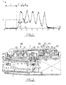
- Figure 1 shows the variations, as a function of time, of the force F applied to a point on the ground - and therefore to the plateau of a mine - when a vehicle passes, a chariot traveling at 2.4 km / h in the example shown.
- the shape of the curves generally has a plurality of peaks, corresponding to the passage of each of the rollers at the point considered.
- a conventional type mine will explode at time t ,, determined as a function of the two parameters S and at t .
- This threshold can for example be fixed by a valve closed by a calibrated spring, which will only start to open and let the compressed fluid escape by the plate only when the pressure of this fluid comes to exceed a certain value.
- a delay L is provided, the minimum duration that the plate will have to take to sink completely and release the striker.
- This delay can for example be defined by a nozzle calibrated in series with the decompression valve, limiting the flow rate of the fluid and therefore the duration of depression of the plate.
- the demining action is not an explosive action, but by passing a mine roller, the mine will not be able to recognize that it is a mine roller and not the first roller of the tank, insofar as the variations in force applied to the platform are substantially the same.
- the system of the invention therefore proposes to trigger the mine either at time t, (because it is not possible to know if the first peak corresponds to the passage of the first roller of the tank, or of a mine clearance roller ), but at time t 2 , that is to say during a further increase in the effort, following the transition to a maximum effort (first peak) then to a minimal effort.
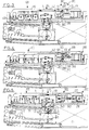
- FIG. 2 shows, in section, an example of a mine structure making it possible to perform this function, the mine being considered in its initial state (phase 1 of FIG. 1).
- the mine comprises an envelope body 1 containing a useful pyrotechnic charge 2 capable of being ignited by release of a striker 3: once released, this striker strikes a primer 4 which initiates a priming and transmission chain fire 5 to trigger the explosion; the chain 5 will be aligned by a delay device 6, par. example a timepiece retarder such as that described in FR-A-2 504 254.
- the striker 3 is released by fully depressing a pressure plate 7 in the upper part of the envelope body 1: this plate is integral in translation with a movable, external sleeve 8 sliding around a fixed, internal sleeve 9.
- the sleeve fixed 9 accommodates keys 10 for retaining the striker 3.
- the keys are immobilized by the lower part of the outer sleeve 8, which moreover includes, in the upper part, recesses 11: during the depression of the outer plate-sleeve assembly, these recesses 11 will be located in line with the keys 10 (cf. FIG. 5), thus releasing the striker 3 which will be able, under the effect of the spring 13, to strike the primer 4 and set the mine on fire.
- the purpose of the hydraulic circuit contained in the pressure plate is to achieve a controlled sinking thereof as a function of the force applied.
- This hydraulic circuit firstly comprises a pressure chamber 100 containing an appropriate fluid, for example an incompressible liquid such as oil (this choice is however in no way limiting, and other fluids can be used, liquids or even gaseous).
- an appropriate fluid for example an incompressible liquid such as oil (this choice is however in no way limiting, and other fluids can be used, liquids or even gaseous).
- the pressure chamber comprises a central chamber 110 closed in the lower part by a movable piston 111 whose lower face is in contact with the upper face 12 of the envelope body 1: this interior chamber 110 is surrounded by an annular chamber 120 closed by a piston 121, an annular piston which, however, is not in contact with the face 12, but is distant from a distance x from the latter.
- the chambers 110 and 120 communicate by means of calibrated orifices 130, the chamber 120 communicating with the rest of the hydraulic circuit by a connecting channel 140.
- the rest of the hydraulic circuit comprises a decompression member 200, of conventional type, and a member control element or bistable element 300, characteristic of the invention, interposed between the pressure chamber 100 and the decompression member 200.
- the pressure relief member 200 includes a pressure relief chamber 210 closed by a calibrated elastic valve 220. Conventionally, this calibrated valve 220 will slow the flow of fluid inside the pressure relief chamber, thus adding a certain constant time to create an “anti-blast” countermeasure.
- the fluid does not need to flow into a closed chamber provided inside the pressure plate; alternatively, it is possible to provide a flow of the fluid directly to the outside.
- the bistable element 300 interposed between the pressure chamber 100 and the decompression member 200, closes in the initial state any communication between these two parts of the circuit.
- This member includes a drawer distributor 310 provided with a passage 311.
- the distributor inlet 320 (which will be called hereinafter “direct actuation input •, insofar as it is this input which will move the drawer towards the open position of the circuit) is connected to the channel 140 in communication with the pressure chamber 100 by means of a non-return valve 321 preventing the delivery of fluid from the distributor to the pressure chamber, but allowing its passage In the opposite way.
- reverse actuation input is, in turn, directly connected to channel 140.
- the inlet channel 340 of the distributor is connected to the channel 140 communicating with the pressure chamber, and its outlet channel 360 is connected to the decompression chamber 210.
- a pressure energy accumulator member 370 comprising a volume 371 of compressible gas (for example air) closed by a movable piston 372.
- fracturable element 400 for example a fracturable pin or a plurality of fracturable pins distributed peripherally, which will prevent any depression of the plate as long as the effort exerted on it will remain below a given threshold. Once this threshold is exceeded, element 400, fractured, will no longer play any functional role.
- the plate will then be able to sink freely, and the piston 111 will compress the fluid contained in the central chamber 110; the fluid will be driven out, via the calibrated orifices 130, into the annular chamber 120, where the resulting pressure increase will push down the annular piston 121. Due to the time constant introduced by the orifices calibrated 130, an “anti-blast” countermeasure is thus operated.
- the two pistons 111 and 121 are both in contact with the upper face 12 of the envelope body and therefore behave like a single piston.
- the increasing pressure will be transmitted to the bistable element 300 via the channel 140.
- the non-return valve 321 being open, the same pressure will be applied to the two actuation inputs, direct and reverse, of the dispenser, so that the position of the drawer 310 will not be changed.
- the compressed fluid will be forced back towards the accumulator member 370, the chamber 373 of which will increase in volume and push back the movable piston 372, thus compressing the volume air 371.
- the pressure will not be able to decrease at the direct actuation input, due to the obstruction brought by the non-return valve 321, which closes as soon as the pressure in the rest of the circuit decreases.
- This pressure differential between the two inlets will cause the slide 310 to move, the channel 311 of which will align with the inlet 340 and outlet 360 channels of the distributor.
- communication is then directly and irreversibly established between the pressure chamber 100 and the decompression member 200.
- the mine then behaves like a conventional mine with a pressure plate: during the recovery of the force (zone IV of FIG. 1), the depression of the pistons 111 and 121 will force the fluid towards the decompression member via the calibrated valve 220 ( Figure 5).
- the fluid will then be discharged from the pressure chamber 100 to the decompression chamber 210 through the channels 140, 340 and 360, the bistable element 300 now being permanently inoperative.
- the countermeasure for explosive demining is mainly carried out by the shut-off valve 220 which opposes a reduced passage for the fluid at the inlet of the decompression chamber. This allows a stroke limitation during a brief impulse with an abrupt rising edge, corresponding to an explosive demining action.
- the striker 3 is released and initiates the pyrotechnic chain, thus causing the explosion of the mine.
Landscapes
- Engineering & Computer Science (AREA)
- General Engineering & Computer Science (AREA)
- Filling Or Discharging Of Gas Storage Vessels (AREA)
- Supply Devices, Intensifiers, Converters, And Telemotors (AREA)
- Safety Valves (AREA)
- Acyclic And Carbocyclic Compounds In Medicinal Compositions (AREA)
- Control Of Fluid Pressure (AREA)
- Manufacture Of Macromolecular Shaped Articles (AREA)
- Fluid-Pressure Circuits (AREA)
Claims (10)
Priority Applications (1)
| Application Number | Priority Date | Filing Date | Title |
|---|---|---|---|
| AT87400181T ATE40007T1 (de) | 1986-01-29 | 1987-01-27 | Druckplatte fuer eine mine, insbesondere zur panzerbekaempfung, und mine mit einer solchen platte. |
Applications Claiming Priority (2)
| Application Number | Priority Date | Filing Date | Title |
|---|---|---|---|
| FR8601238A FR2593597B1 (fr) | 1986-01-29 | 1986-01-29 | Plateau de pression pour mine, notamment antichar, et mine pourvue d'un tel plateau |
| FR8601238 | 1986-01-29 |
Publications (2)
| Publication Number | Publication Date |
|---|---|
| EP0236176A1 EP0236176A1 (de) | 1987-09-09 |
| EP0236176B1 true EP0236176B1 (de) | 1989-01-11 |
Family
ID=9331600
Family Applications (1)
| Application Number | Title | Priority Date | Filing Date |
|---|---|---|---|
| EP87400181A Expired EP0236176B1 (de) | 1986-01-29 | 1987-01-27 | Druckplatte für eine Mine, insbesondere zur Panzerbekämpfung, und Mine mit einer solchen Platte |
Country Status (7)
| Country | Link |
|---|---|
| US (1) | US4718347A (de) |
| EP (1) | EP0236176B1 (de) |
| AT (1) | ATE40007T1 (de) |
| CA (1) | CA1295883C (de) |
| DE (1) | DE3760040D1 (de) |
| ES (1) | ES2005818B3 (de) |
| FR (1) | FR2593597B1 (de) |
Families Citing this family (1)
| Publication number | Priority date | Publication date | Assignee | Title |
|---|---|---|---|---|
| US5238512A (en) * | 1987-06-04 | 1993-08-24 | Exploweld Ab | Water resistant elastic explosive mixture |
Family Cites Families (5)
| Publication number | Priority date | Publication date | Assignee | Title |
|---|---|---|---|---|
| NL82382C (de) * | 1950-12-02 | |||
| NL101799C (de) * | 1954-10-06 | |||
| US3282212A (en) * | 1963-06-13 | 1966-11-01 | Brind Anstalt Ind | Antimagnetic war-mine suitable for rapid setting and sowing |
| FR2357860A1 (fr) * | 1976-07-08 | 1978-02-03 | Lacroix E | Mine antichar indetectable |
| FR2504254B1 (fr) * | 1981-04-15 | 1986-01-10 | Lacroix E Tous Artifices | Mine antichar perfectionnee |
-
1986
- 1986-01-29 FR FR8601238A patent/FR2593597B1/fr not_active Expired
-
1987
- 1987-01-27 DE DE8787400181T patent/DE3760040D1/de not_active Expired
- 1987-01-27 EP EP87400181A patent/EP0236176B1/de not_active Expired
- 1987-01-27 AT AT87400181T patent/ATE40007T1/de not_active IP Right Cessation
- 1987-01-27 US US07/006,950 patent/US4718347A/en not_active Expired - Fee Related
- 1987-01-27 ES ES87400181T patent/ES2005818B3/es not_active Expired - Lifetime
- 1987-01-28 CA CA000528422A patent/CA1295883C/fr not_active Expired - Lifetime
Also Published As
| Publication number | Publication date |
|---|---|
| ES2005818B3 (es) | 1992-03-01 |
| EP0236176A1 (de) | 1987-09-09 |
| FR2593597B1 (fr) | 1988-05-13 |
| ATE40007T1 (de) | 1989-01-15 |
| US4718347A (en) | 1988-01-12 |
| DE3760040D1 (en) | 1989-02-16 |
| CA1295883C (fr) | 1992-02-18 |
| FR2593597A1 (fr) | 1987-07-31 |
Similar Documents
| Publication | Publication Date | Title |
|---|---|---|
| EP0048204B1 (de) | Patrone mit pyrotechnisch betätigter Nutzladung und mit Sicherheitseinrichtungen | |
| FR2638484A1 (fr) | Dispositif d'actionnement, operant hydrauliquement, pour une soupape de lancement, notamment dans un moteur a combustion interne | |
| FR2474101A1 (fr) | Dispositif d'injection a regeneration, equipe de valves, pour moteur-fusee | |
| FR2516037A1 (fr) | Perfectionnements a des systemes de freinage hydraulique antipatinage pour vehicules | |
| EP1486697B1 (de) | Modulierbarer Dämpfer mit pyrotechnischen Gasen | |
| FR2704924A1 (fr) | Vanne pyrotechnique. | |
| EP0150138A2 (de) | Sicherheitsvorrichtung für Gleichdruckeinspritzventil einer Brennkraftmaschine | |
| EP0236176A1 (de) | Druckplatte für eine Mine, insbesondere zur Panzerbekämpfung, und Mine mit einer solchen Platte | |
| EP0094466B1 (de) | Panzerbrechende Mine | |
| FR3044572A1 (fr) | Dispositif brise roches | |
| EP0545764A1 (de) | Verriegelungsvorrichtung einer Hülse die pyrotechnische Materialien enthält | |
| FR3005724A1 (fr) | Generateur de gaz pyrotechnique | |
| EP1902214B1 (de) | Druckentlastungsvorrichtung | |
| EP0019509A1 (de) | Verzögerungsabhängiger Bremskraftregler | |
| EP0161131A1 (de) | Sicherheitsvorrichtung für einen Bremskraftregler | |
| EP2769168B1 (de) | Gasgenerator mit einer sicherheitsvorrichtung für langsame erhitzung | |
| EP0090739B1 (de) | Elektromagnetische Einspritzanlage für Dieselmotoren die einen Einspritzverlauf der "Druck-Zeit"-Type erzeugt | |
| WO2004076962A1 (fr) | Fusee de projectile | |
| FR2552514A1 (fr) | Amortisseur du type fluidique | |
| EP0000303B1 (de) | Hydraulischer Selbstschalter | |
| EP0278837B1 (de) | Zeitzünder für beliebige Aufschlagrichtung für Munition zum Abschuss aus Feuerwaffen, insbesondere für Granaten | |
| WO2007144396A1 (fr) | Allumeur de securite pour dispositif pyrotechnique | |
| BE824041A (fr) | Cartouche pour la dispersion de leurres electromagnetiques. | |
| FR2929126A1 (fr) | Dispositif d'ejection d'un fluide muni d'un dispositif anti-retour | |
| WO2001062553A1 (fr) | Procede et dispositif d'amortissement de choc pour vehicule ferroviaire |
Legal Events
| Date | Code | Title | Description |
|---|---|---|---|
| PUAI | Public reference made under article 153(3) epc to a published international application that has entered the european phase |
Free format text: ORIGINAL CODE: 0009012 |
|
| AK | Designated contracting states |
Kind code of ref document: A1 Designated state(s): AT BE CH DE ES FR GB GR IT LI LU NL SE |
|
| 17P | Request for examination filed |
Effective date: 19871026 |
|
| 17Q | First examination report despatched |
Effective date: 19880502 |
|
| GRAA | (expected) grant |
Free format text: ORIGINAL CODE: 0009210 |
|
| AK | Designated contracting states |
Kind code of ref document: B1 Designated state(s): AT BE CH DE ES FR GB GR IT LI LU NL SE |
|
| PG25 | Lapsed in a contracting state [announced via postgrant information from national office to epo] |
Ref country code: GR Free format text: LAPSE BECAUSE OF FAILURE TO SUBMIT A TRANSLATION OF THE DESCRIPTION OR TO PAY THE FEE WITHIN THE PRESCRIBED TIME-LIMIT Effective date: 19890111 Ref country code: GB Free format text: LAPSE BECAUSE OF NON-PAYMENT OF DUE FEES Effective date: 19890111 Ref country code: IT Free format text: LAPSE BECAUSE OF FAILURE TO SUBMIT A TRANSLATION OF THE DESCRIPTION OR TO PAY THE FEE WITHIN THE PRE;WARNING: LAPSES OF ITALIAN PATENTS WITH EFFECTIVE DATE BEFORE 2007 MAY HAVE OCCURRED AT ANY TIME BEFORE 2007. THE CORRECT EFFECTIVE DATE MAY BE DIFFERENT FROM THE ONE RECORDED.SCRIBED TIME-LIMIT Effective date: 19890111 Ref country code: SE Effective date: 19890111 Ref country code: AT Effective date: 19890111 |
|
| REF | Corresponds to: |
Ref document number: 40007 Country of ref document: AT Date of ref document: 19890115 Kind code of ref document: T |
|
| REF | Corresponds to: |
Ref document number: 3760040 Country of ref document: DE Date of ref document: 19890216 |
|
| GBV | Gb: ep patent (uk) treated as always having been void in accordance with gb section 77(7)/1977 [no translation filed] | ||
| PLBE | No opposition filed within time limit |
Free format text: ORIGINAL CODE: 0009261 |
|
| STAA | Information on the status of an ep patent application or granted ep patent |
Free format text: STATUS: NO OPPOSITION FILED WITHIN TIME LIMIT |
|
| 26N | No opposition filed | ||
| PGFP | Annual fee paid to national office [announced via postgrant information from national office to epo] |
Ref country code: DE Payment date: 19920118 Year of fee payment: 6 |
|
| PGFP | Annual fee paid to national office [announced via postgrant information from national office to epo] |
Ref country code: ES Payment date: 19920131 Year of fee payment: 6 Ref country code: NL Payment date: 19920131 Year of fee payment: 6 |
|
| PGFP | Annual fee paid to national office [announced via postgrant information from national office to epo] |
Ref country code: LU Payment date: 19920219 Year of fee payment: 6 |
|
| PGFP | Annual fee paid to national office [announced via postgrant information from national office to epo] |
Ref country code: BE Payment date: 19920514 Year of fee payment: 6 |
|
| EPTA | Lu: last paid annual fee | ||
| PG25 | Lapsed in a contracting state [announced via postgrant information from national office to epo] |
Ref country code: LU Free format text: LAPSE BECAUSE OF NON-PAYMENT OF DUE FEES Effective date: 19930127 |
|
| PG25 | Lapsed in a contracting state [announced via postgrant information from national office to epo] |
Ref country code: ES Free format text: LAPSE BECAUSE OF NON-PAYMENT OF DUE FEES Effective date: 19930128 |
|
| PG25 | Lapsed in a contracting state [announced via postgrant information from national office to epo] |
Ref country code: BE Effective date: 19930131 |
|
| PGFP | Annual fee paid to national office [announced via postgrant information from national office to epo] |
Ref country code: CH Payment date: 19930217 Year of fee payment: 7 |
|
| BERE | Be: lapsed |
Owner name: ETIENNE LACROIX TOUS ARTIFICES S.A. Effective date: 19930131 |
|
| PG25 | Lapsed in a contracting state [announced via postgrant information from national office to epo] |
Ref country code: NL Effective date: 19930801 |
|
| NLV4 | Nl: lapsed or anulled due to non-payment of the annual fee | ||
| PG25 | Lapsed in a contracting state [announced via postgrant information from national office to epo] |
Ref country code: DE Effective date: 19931001 |
|
| PG25 | Lapsed in a contracting state [announced via postgrant information from national office to epo] |
Ref country code: LI Effective date: 19940131 Ref country code: CH Effective date: 19940131 |
|
| REG | Reference to a national code |
Ref country code: CH Ref legal event code: PL |
|
| REG | Reference to a national code |
Ref country code: ES Ref legal event code: FD2A Effective date: 19990201 |
|
| PGFP | Annual fee paid to national office [announced via postgrant information from national office to epo] |
Ref country code: FR Payment date: 20030110 Year of fee payment: 17 |
|
| PG25 | Lapsed in a contracting state [announced via postgrant information from national office to epo] |
Ref country code: FR Free format text: LAPSE BECAUSE OF NON-PAYMENT OF DUE FEES Effective date: 20040930 |
|
| REG | Reference to a national code |
Ref country code: FR Ref legal event code: ST |